EP4531264A1 - Piezoelektrischer hochleistungsmotor und antrieb - Google Patents
Piezoelektrischer hochleistungsmotor und antrieb Download PDFInfo
- Publication number
- EP4531264A1 EP4531264A1 EP23208367.5A EP23208367A EP4531264A1 EP 4531264 A1 EP4531264 A1 EP 4531264A1 EP 23208367 A EP23208367 A EP 23208367A EP 4531264 A1 EP4531264 A1 EP 4531264A1
- Authority
- EP
- European Patent Office
- Prior art keywords
- stator
- motor
- ring
- teeth
- piezoelectric
- Prior art date
- Legal status (The legal status is an assumption and is not a legal conclusion. Google has not performed a legal analysis and makes no representation as to the accuracy of the status listed.)
- Granted
Links
Images


Classifications
-
- H—ELECTRICITY
- H02—GENERATION; CONVERSION OR DISTRIBUTION OF ELECTRIC POWER
- H02N—ELECTRIC MACHINES NOT OTHERWISE PROVIDED FOR
- H02N2/00—Electric machines in general using piezoelectric effect, electrostriction or magnetostriction
- H02N2/10—Electric machines in general using piezoelectric effect, electrostriction or magnetostriction producing rotary motion, e.g. rotary motors
- H02N2/16—Electric machines in general using piezoelectric effect, electrostriction or magnetostriction producing rotary motion, e.g. rotary motors using travelling waves, i.e. Rayleigh surface waves
- H02N2/163—Motors with ring stator
-
- H—ELECTRICITY
- H02—GENERATION; CONVERSION OR DISTRIBUTION OF ELECTRIC POWER
- H02N—ELECTRIC MACHINES NOT OTHERWISE PROVIDED FOR
- H02N2/00—Electric machines in general using piezoelectric effect, electrostriction or magnetostriction
- H02N2/10—Electric machines in general using piezoelectric effect, electrostriction or magnetostriction producing rotary motion, e.g. rotary motors
- H02N2/101—Electric machines in general using piezoelectric effect, electrostriction or magnetostriction producing rotary motion, e.g. rotary motors using intermittent driving, e.g. step motors
-
- H—ELECTRICITY
- H02—GENERATION; CONVERSION OR DISTRIBUTION OF ELECTRIC POWER
- H02N—ELECTRIC MACHINES NOT OTHERWISE PROVIDED FOR
- H02N2/00—Electric machines in general using piezoelectric effect, electrostriction or magnetostriction
- H02N2/02—Electric machines in general using piezoelectric effect, electrostriction or magnetostriction producing linear motion, e.g. actuators; Linear positioners ; Linear motors
- H02N2/021—Electric machines in general using piezoelectric effect, electrostriction or magnetostriction producing linear motion, e.g. actuators; Linear positioners ; Linear motors using intermittent driving, e.g. step motors, piezoleg motors
-
- H—ELECTRICITY
- H02—GENERATION; CONVERSION OR DISTRIBUTION OF ELECTRIC POWER
- H02N—ELECTRIC MACHINES NOT OTHERWISE PROVIDED FOR
- H02N2/00—Electric machines in general using piezoelectric effect, electrostriction or magnetostriction
- H02N2/02—Electric machines in general using piezoelectric effect, electrostriction or magnetostriction producing linear motion, e.g. actuators; Linear positioners ; Linear motors
- H02N2/08—Electric machines in general using piezoelectric effect, electrostriction or magnetostriction producing linear motion, e.g. actuators; Linear positioners ; Linear motors using travelling waves, i.e. Rayleigh surface waves
Definitions
- the Taiwanese patent TWI450489B describes a small-sized rotary motor with a high torque and high angular resolution.
- the motor consists of a square-sectioned rod-shaped stator with flanges formed at both ends, and one of the ends has a conical cavity.
- the conical rotor is placed in the stator's conical cavity.
- frictional force is generated between the rotor and the stator, which can be modified by adjusting the clamping system spring.
- Four piezoelectric multilayer transducers are mounted parallel to the edges of the stator, with their ends resting on the flanges formed at the ends of the stator.
- US patent US6628045B2 describes a piezoelectric ring-shaped rotary motor, consisting of a stator composed of an elastic toothed ring-shaped stator with a firmly attached piezoelectric ring, a disc-shaped rotor, and a rotor clamping system.
- the piezoelectric ring electrode is divided into equal parts.
- stator teeth influence the amplitude of bending oscillations in the contact zone between the stator and rotor, allowing the maximum torque and the speed of the motor to be increased.
- the use of a toothed stator to obtain high torque has a drawback - the maximum torque is limited by the tooth height and clamping force. When a certain ratio of tooth height to rotor clamping force is reached, the stator teeth begin to buckle, limiting the increase in the motor's torque.
- the goal of the invention is achieved by forming double-sided teeth in the ring-shaped piezoelectric motor stator, with their position chosen to coincide with the ring's own longitudinal oscillation nodes.
- the height of the double-sided teeth, including the stator height, is equal to or close to half the wavelength of the oscillations excited in the ring.
- Notches are formed on the horizontal symmetry axes of these double-sided teeth, which reduces the overall height of the motor and allows for larger displacement of tooth tips and rotor rotational speed.
- Rigid frictional elements are mounted on the top surfaces of the teeth, and two disc-shaped rotors are spring-clamped against them.
- stator longitudinal oscillations are induced by the excitation of the piezoelectric transducers mounted in the nodal zones of the stator ring's longitudinal oscillations, by one or two electrical harmonic signals, the phase difference of which is determined by ⁇ / 2, or by two non-harmonic periodic signals, the phase difference of which is determined by ⁇ , and the frequency is tuned close to or coinciding with the resonant frequency of the ring stator's longitudinal oscillations.
- the motor's torque and force are increased when the teeth are formed on both sides of the stator.
- double-sided teeth in the stator's flat ring with a total height chosen to be close or equal to half the wavelength of the stator's longitudinal oscillation.
- the stability of the motor operation is enhanced by the trapezoidal or analogous shape of the double-sided teeth of the stator, the long base of which is on the stator ring. This feature reduces or eliminates stator teeth buckling under the high axial loads of the motor.
- the functional capabilities of the motor are extended by using several different excitation circuits for individual piezoelectric actuators (Langevin-type packages) or their groups, the sequence of piezoelectric actuator excitation, and the parameters of electrical excitation signals.
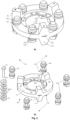
- a piezoelectric rotary motion motor includes the following parts: a flexible ring-shaped stator (1) with two flat surfaces, on which double-sided teeth are arranged radially (7) with their wider end directed towards the stator base, having any shape that widens toward the base: symmetrical trapezoidal prisms, cones, hemispheres, or semi ellipsoids. Together, the ring and its double-sided teeth form the complete structure of the stator (1).
- This stator structure is made from one-piece elastic material, such as steel, aluminium, or bronze alloys.
- the disc-shaped rotors (2) are pressed onto the aforementioned stator teeth (7) using springs.
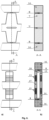
- a longitudinal notch (9) is formed in the horizontal axis of symmetry of each double-sided trapezoidal tooth (7) and, at the same time, in the plane of the stator ring. This reduces the structural stiffness of the stator and allows sufficient amplitude to be achieved of the apical displacement of the double-sided trapezoidal teeth (7) at the reduced height of both the trapezoidal teeth and the complete motor (drive).
- Rigid contact-friction (support) elements (8) are placed on the upper and lower planes of the double-sided teeth (7). These contact-friction elements (8) come into direct contact with the two disc-shaped rotors (2) connected to the drive shaft (5). In this way, the rotors connected and clamped form a tribological pair, whose clamping force against the friction elements (8) of the stator teeth can be changed by compressing or releasing the clamping spring (3). The compression/release of the spring is controlled by the vertical position of the compression nuts (4) on the drive shaft (5).
- the motor rotors (2) are made of a hard material, similar to the contact-frictional elements (8).
- the motor stator (1) is anchored in the drive using the stator anchor ring (10).
- This ring is connected to the stator (1) permanently and in such a way that the connection points of the anchor ring (10) and the stator (1) coincide with the nodal zones of the longitudinal oscillations excited in the stator (1).
- the ring-shaped stator (1) also incorporates piezoelectric actuators, such as Langevin-type packages (11). The distribution of the piezoelectric actuators in the ring shall be chosen to coincide with the nodes of the longitudinal oscillations excited in the ring-shaped stator (1).
- the Langevin package (11) consists of an upper part (13), piezoelectric rings (15), a lower part (14), and a package fixing screw (12), which is used for the removable attachment of the piezoelectric Langevin package (11) to the ring stator (1).
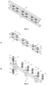
- Linear motion motor Another possible implementation of this invention is a linear motion motor.
- the stator (17) is in the form of an flexible rod and linear sliders (16) are used instead of the two disc-shaped rotors (2).
- the screw (12) can be replaced by a stud (18).
- the design and installation principles of the trapezoidal double-sided teeth (7) and the piezoelectric Langevin packages (11) described above are the same as those of the rotary motor. This linear motion motor generates a linear motion.
- the rotary motion (16) of a pair of disc-shaped rotors (2) is obtained by applying harmonic or non-harmonic periodic electrical signals to piezoelectric Langevin-type packages (11), using an excitation switching device (21) and a signal generator (20), the parameters of which, such as frequency, amplitude, phase, and waveform, are matched to the electromechanical characteristics of the drive.
- the excitation signals to the motor's Langevin packages (11) can be formed by three different excitation circuit diagrams.
- Excitation circuit diagram 1 In the first excitation circuit diagram, the rotational motion of the disc-shaped rotor (2) is excited by the first group of Langevin packages (22). This group shall be excited via the electrical excitation signal switching device (21) by a harmonic electrical signal at a frequency f matched to the resonance frequency of the longitudinal oscillations of the ring stator (1). Meanwhile, the second group of Langevin packages (23) does not receive an electrical signal and remains passive.
- the first group (22) of Langevin packages (11) under the influence of the excitation signal, deforms the flexible ring stator (1) in the transverse direction and also in the longitudinal direction due to the deformation produced by the Poisson's ratio, by synchronously expanding and contracting along their vertical axis of symmetry.
- the double-sided trapezoidal teeth (7) are bent because of the notches (9).
- the bending oscillations of the double-sided trapezoidal teeth (7) are transmitted to the disc-shaped rotors (2) via rigid friction elements (8), thus generating the rotary motion of the rotors.
- a second group of Langevin packages (23) is excited via the signal switching device (21), while the first group (22) is no longer excited.
- Excitation circuit diagram 2 In the second excitation circuit diagram, the rotational motion of the disc rotor (2) is excited by the first and second groups of piezoelectric packages (22, 23). Via the electrical excitation signal switching device (21), the two groups are exposed in parallel to two harmonic signals with a phase difference set at ⁇ / 2 , and a frequency f matched to the longitudinal oscillation resonance frequency of the ring stator (1). Acting asynchronously in groups, the Langevin packages (11) stretch and contract along their vertical axis of symmetry. Due to the flexibility of the material of the stator (1) and the Poisson's ratio, they excite the longitudinal oscillations in the stator (1), thus producing travelling-wave oscillation.
- the tips of the double-sided trapezoidal teeth (7) being bent form elliptical trajectories of motion, which are passed on through the rigid friction elements (8) to the disc-shaped rotors (2).
- the rotor (2) is excited to rotate in the opposite direction by the same harmonic excitation signals from the electrical signal switching device (21), but swapped between the two groups of Langevin packages (22, 23) mentioned above.
- Excitation circuit diagram 3 In the third excitation circuit diagram, the rotational movement of the disc-shaped rotors (2) is formed by the first and second groups of piezoelectric packages (22, 23). The two groups are subjected in parallel, via the electrical excitation switching device (21), to two asymmetrical periodic signals, whose phase difference is set to ⁇ , and whose frequency f is adjusted to be close to, or equal to, the frequency of the longitudinal oscillations of the ring stator (1). Due to the asymmetric shape of the excitation signal, the Langevin packages (11) stretch and contract at different rates. The bending strain rate of the double-sided trapezoidal teeth (7) is also different due to the different rates of contraction and expansion and the longitudinal oscillations induced in the ring stator (1).
- This piezoelectric motor design can be applied in high-precision gyroscopic spatial or other types of positioning systems used to control the position of objects in space, such as micro and nano satellites. That is, to determine, control, and continuously correct the spatial orientation of an object (e.g. self-orienting satellites or space vehicles) during their uninterruptible operational cycle.
- an object e.g. self-orienting satellites or space vehicles
Landscapes
- General Electrical Machinery Utilizing Piezoelectricity, Electrostriction Or Magnetostriction (AREA)
Applications Claiming Priority (1)
| Application Number | Priority Date | Filing Date | Title |
|---|---|---|---|
| LT2023016A LT7061B (lt) | 2023-09-29 | 2023-09-29 | Didelės galios pjezoelektrinis variklis su valdymo sistema |
Publications (2)
| Publication Number | Publication Date |
|---|---|
| EP4531264A1 true EP4531264A1 (de) | 2025-04-02 |
| EP4531264B1 EP4531264B1 (de) | 2025-10-29 |
Family
ID=88745803
Family Applications (1)
| Application Number | Title | Priority Date | Filing Date |
|---|---|---|---|
| EP23208367.5A Active EP4531264B1 (de) | 2023-09-29 | 2023-11-07 | Piezoelektrischer hochleistungsmotor und antrieb |
Country Status (2)
| Country | Link |
|---|---|
| EP (1) | EP4531264B1 (de) |
| LT (1) | LT7061B (de) |
Cited By (1)
| Publication number | Priority date | Publication date | Assignee | Title |
|---|---|---|---|---|
| CN120342251A (zh) * | 2025-06-19 | 2025-07-18 | 合肥工业大学 | 一种多模态双向运动旋转压电马达 |
Citations (6)
| Publication number | Priority date | Publication date | Assignee | Title |
|---|---|---|---|---|
| JP2000152671A (ja) | 1998-11-05 | 2000-05-30 | Japan Science & Technology Corp | 超音波モータ |
| US6262515B1 (en) * | 2000-02-18 | 2001-07-17 | Honeywell International, Inc. | Piezoelectric wave motor |
| WO2003010879A2 (en) * | 2001-07-23 | 2003-02-06 | Abb Service S.R.L. | Driving device for ultrasonic motor |
| US6628045B2 (en) | 2000-12-15 | 2003-09-30 | Korea Institute Of Science And Technology | Ring-type piezoelectric ultrasonic motor |
| US20060145572A1 (en) * | 2003-01-08 | 2006-07-06 | Physik Instrumente (Pi) Gmbh Co. Kg | Method for operating a piezoelectric motor, and a piezoelectric motor having a startor in the form of a hollow-cylindrical oscillator |
| CN110677073A (zh) * | 2019-11-05 | 2020-01-10 | 山东理工大学 | 贴片式行波型双面交错齿超声电机定子 |
Family Cites Families (1)
| Publication number | Priority date | Publication date | Assignee | Title |
|---|---|---|---|---|
| TWI450489B (zh) | 2012-03-07 | 2014-08-21 | Univ Cheng Shiu | 高致動力壓電馬達 |
-
2023
- 2023-09-29 LT LT2023016A patent/LT7061B/lt unknown
- 2023-11-07 EP EP23208367.5A patent/EP4531264B1/de active Active
Patent Citations (6)
| Publication number | Priority date | Publication date | Assignee | Title |
|---|---|---|---|---|
| JP2000152671A (ja) | 1998-11-05 | 2000-05-30 | Japan Science & Technology Corp | 超音波モータ |
| US6262515B1 (en) * | 2000-02-18 | 2001-07-17 | Honeywell International, Inc. | Piezoelectric wave motor |
| US6628045B2 (en) | 2000-12-15 | 2003-09-30 | Korea Institute Of Science And Technology | Ring-type piezoelectric ultrasonic motor |
| WO2003010879A2 (en) * | 2001-07-23 | 2003-02-06 | Abb Service S.R.L. | Driving device for ultrasonic motor |
| US20060145572A1 (en) * | 2003-01-08 | 2006-07-06 | Physik Instrumente (Pi) Gmbh Co. Kg | Method for operating a piezoelectric motor, and a piezoelectric motor having a startor in the form of a hollow-cylindrical oscillator |
| CN110677073A (zh) * | 2019-11-05 | 2020-01-10 | 山东理工大学 | 贴片式行波型双面交错齿超声电机定子 |
Cited By (1)
| Publication number | Priority date | Publication date | Assignee | Title |
|---|---|---|---|---|
| CN120342251A (zh) * | 2025-06-19 | 2025-07-18 | 合肥工业大学 | 一种多模态双向运动旋转压电马达 |
Also Published As
| Publication number | Publication date |
|---|---|
| LT7061B (lt) | 2024-05-10 |
| EP4531264B1 (de) | 2025-10-29 |
| LT2023016A (lt) | 2024-04-10 |
Similar Documents
| Publication | Publication Date | Title |
|---|---|---|
| EP0674350B1 (de) | Ultraschallmotor | |
| EP0308970B1 (de) | Piezoelektrischer Motor | |
| US4933590A (en) | Ultrasonic motor | |
| Suzuki et al. | Development of a new type piezoelectric micromotor | |
| JP3823340B2 (ja) | 振動モータ | |
| EP4531264A1 (de) | Piezoelektrischer hochleistungsmotor und antrieb | |
| US5001382A (en) | Stepping motor and a method of driving the same | |
| CN100525055C (zh) | 压电电机和用于驱动该压电电机的方法 | |
| KR20070004523A (ko) | 초음파 리드 나사 모터 | |
| JP4901597B2 (ja) | 振動型アクチュエータ | |
| JPS62259485A (ja) | 圧電駆動装置 | |
| JP4032161B2 (ja) | アクチュエータ | |
| Schaaf | Pushy motors (piezoelectric motors) | |
| JPH09322572A (ja) | 振動アクチュエータ | |
| JP2001136761A (ja) | アクチュエータ | |
| JPH08242592A (ja) | 超音波アクチュエータ | |
| JP4352511B2 (ja) | トラス型アクチュエータ | |
| EP0370508B1 (de) | Ultraschallantrieb | |
| JPH0552137B2 (de) | ||
| JP2001016879A (ja) | 超音波モータ及びその駆動方法 | |
| Koc et al. | Design of a piezoelectric ultrasonic motor for micro-robotic application | |
| LT7111B (lt) | Didelės galios pjezoelektrinė sukamoji pavara | |
| LT7104B (lt) | Inercinė keturių laisvės laipsnių pjezoelektrinė pavara | |
| JPH09219979A (ja) | 振動アクチュエータ | |
| JP2012100482A (ja) | 振動型駆動装置 |
Legal Events
| Date | Code | Title | Description |
|---|---|---|---|
| PUAI | Public reference made under article 153(3) epc to a published international application that has entered the european phase |
Free format text: ORIGINAL CODE: 0009012 |
|
| STAA | Information on the status of an ep patent application or granted ep patent |
Free format text: STATUS: REQUEST FOR EXAMINATION WAS MADE |
|
| 17P | Request for examination filed |
Effective date: 20240605 |
|
| AK | Designated contracting states |
Kind code of ref document: A1 Designated state(s): AL AT BE BG CH CY CZ DE DK EE ES FI FR GB GR HR HU IE IS IT LI LT LU LV MC ME MK MT NL NO PL PT RO RS SE SI SK SM TR |
|
| GRAP | Despatch of communication of intention to grant a patent |
Free format text: ORIGINAL CODE: EPIDOSNIGR1 |
|
| STAA | Information on the status of an ep patent application or granted ep patent |
Free format text: STATUS: GRANT OF PATENT IS INTENDED |
|
| RIC1 | Information provided on ipc code assigned before grant |
Ipc: H02N 2/16 20060101ALI20250528BHEP Ipc: H02N 2/12 20060101ALI20250528BHEP Ipc: H02N 2/10 20060101ALI20250528BHEP Ipc: H02N 2/08 20060101ALI20250528BHEP Ipc: H02N 2/02 20060101ALI20250528BHEP Ipc: H02N 2/00 20060101AFI20250528BHEP |
|
| INTG | Intention to grant announced |
Effective date: 20250623 |
|
| GRAS | Grant fee paid |
Free format text: ORIGINAL CODE: EPIDOSNIGR3 |
|
| GRAA | (expected) grant |
Free format text: ORIGINAL CODE: 0009210 |
|
| STAA | Information on the status of an ep patent application or granted ep patent |
Free format text: STATUS: THE PATENT HAS BEEN GRANTED |
|
| AK | Designated contracting states |
Kind code of ref document: B1 Designated state(s): AL AT BE BG CH CY CZ DE DK EE ES FI FR GB GR HR HU IE IS IT LI LT LU LV MC ME MK MT NL NO PL PT RO RS SE SI SK SM TR |
|
| REG | Reference to a national code |
Ref country code: CH Ref legal event code: F10 Free format text: ST27 STATUS EVENT CODE: U-0-0-F10-F00 (AS PROVIDED BY THE NATIONAL OFFICE) Effective date: 20251029 Ref country code: GB Ref legal event code: FG4D |
|
| REG | Reference to a national code |
Ref country code: IE Ref legal event code: FG4D |
|
| REG | Reference to a national code |
Ref country code: DE Ref legal event code: R096 Ref document number: 602023008009 Country of ref document: DE |
|
| PGFP | Annual fee paid to national office [announced via postgrant information from national office to epo] |
Ref country code: AT Payment date: 20260113 Year of fee payment: 3 |
|
| REG | Reference to a national code |
Ref country code: NL Ref legal event code: MP Effective date: 20251029 |
|
| PG25 | Lapsed in a contracting state [announced via postgrant information from national office to epo] |
Ref country code: ES Free format text: LAPSE BECAUSE OF FAILURE TO SUBMIT A TRANSLATION OF THE DESCRIPTION OR TO PAY THE FEE WITHIN THE PRESCRIBED TIME-LIMIT Effective date: 20251029 |
|
| REG | Reference to a national code |
Ref country code: LT Ref legal event code: MG9D |
|
| PG25 | Lapsed in a contracting state [announced via postgrant information from national office to epo] |
Ref country code: NO Free format text: LAPSE BECAUSE OF FAILURE TO SUBMIT A TRANSLATION OF THE DESCRIPTION OR TO PAY THE FEE WITHIN THE PRESCRIBED TIME-LIMIT Effective date: 20260129 |
|
| PG25 | Lapsed in a contracting state [announced via postgrant information from national office to epo] |
Ref country code: FI Free format text: LAPSE BECAUSE OF FAILURE TO SUBMIT A TRANSLATION OF THE DESCRIPTION OR TO PAY THE FEE WITHIN THE PRESCRIBED TIME-LIMIT Effective date: 20251029 Ref country code: HR Free format text: LAPSE BECAUSE OF FAILURE TO SUBMIT A TRANSLATION OF THE DESCRIPTION OR TO PAY THE FEE WITHIN THE PRESCRIBED TIME-LIMIT Effective date: 20251029 Ref country code: AT Free format text: LAPSE BECAUSE OF FAILURE TO SUBMIT A TRANSLATION OF THE DESCRIPTION OR TO PAY THE FEE WITHIN THE PRESCRIBED TIME-LIMIT Effective date: 20251029 |
|
| REG | Reference to a national code |
Ref country code: AT Ref legal event code: MK05 Ref document number: 1852829 Country of ref document: AT Kind code of ref document: T Effective date: 20251029 |
|
| PG25 | Lapsed in a contracting state [announced via postgrant information from national office to epo] |
Ref country code: NL Free format text: LAPSE BECAUSE OF FAILURE TO SUBMIT A TRANSLATION OF THE DESCRIPTION OR TO PAY THE FEE WITHIN THE PRESCRIBED TIME-LIMIT Effective date: 20251029 |
|
| PG25 | Lapsed in a contracting state [announced via postgrant information from national office to epo] |
Ref country code: RS Free format text: LAPSE BECAUSE OF FAILURE TO SUBMIT A TRANSLATION OF THE DESCRIPTION OR TO PAY THE FEE WITHIN THE PRESCRIBED TIME-LIMIT Effective date: 20260129 |
|
| PG25 | Lapsed in a contracting state [announced via postgrant information from national office to epo] |
Ref country code: IS Free format text: LAPSE BECAUSE OF FAILURE TO SUBMIT A TRANSLATION OF THE DESCRIPTION OR TO PAY THE FEE WITHIN THE PRESCRIBED TIME-LIMIT Effective date: 20260228 |