EP4531422A1 - Procédé et dispositif de mappage de service de client, support de stockage et dispositif électronique - Google Patents
Procédé et dispositif de mappage de service de client, support de stockage et dispositif électronique Download PDFInfo
- Publication number
- EP4531422A1 EP4531422A1 EP23829351.8A EP23829351A EP4531422A1 EP 4531422 A1 EP4531422 A1 EP 4531422A1 EP 23829351 A EP23829351 A EP 23829351A EP 4531422 A1 EP4531422 A1 EP 4531422A1
- Authority
- EP
- European Patent Office
- Prior art keywords
- overhead
- bit rate
- client
- container
- units
- Prior art date
- Legal status (The legal status is an assumption and is not a legal conclusion. Google has not performed a legal analysis and makes no representation as to the accuracy of the status listed.)
- Pending
Links
Images

Classifications
-
- H—ELECTRICITY
- H04—ELECTRIC COMMUNICATION TECHNIQUE
- H04Q—SELECTING
- H04Q11/00—Selecting arrangements for multiplex systems
- H04Q11/0001—Selecting arrangements for multiplex systems using optical switching
- H04Q11/0062—Network aspects
- H04Q11/0067—Provisions for optical access or distribution networks, e.g. Gigabit Ethernet Passive Optical Network (GE-PON), ATM-based Passive Optical Network (A-PON), PON-Ring
-
- H—ELECTRICITY
- H04—ELECTRIC COMMUNICATION TECHNIQUE
- H04J—MULTIPLEX COMMUNICATION
- H04J3/00—Time-division multiplex systems
- H04J3/16—Time-division multiplex systems in which the time allocation to individual channels within a transmission cycle is variable, e.g. to accommodate varying complexity of signals, to vary number of channels transmitted
- H04J3/1605—Fixed allocated frame structures
- H04J3/1652—Optical Transport Network [OTN]
-
- H—ELECTRICITY
- H04—ELECTRIC COMMUNICATION TECHNIQUE
- H04L—TRANSMISSION OF DIGITAL INFORMATION, e.g. TELEGRAPHIC COMMUNICATION
- H04L67/00—Network arrangements or protocols for supporting network services or applications
- H04L67/50—Network services
- H04L67/535—Tracking the activity of the user
-
- H—ELECTRICITY
- H04—ELECTRIC COMMUNICATION TECHNIQUE
- H04L—TRANSMISSION OF DIGITAL INFORMATION, e.g. TELEGRAPHIC COMMUNICATION
- H04L69/00—Network arrangements, protocols or services independent of the application payload and not provided for in the other groups of this subclass
- H04L69/06—Notations for structuring of protocol data, e.g. abstract syntax notation one [ASN.1]
-
- H—ELECTRICITY
- H04—ELECTRIC COMMUNICATION TECHNIQUE
- H04Q—SELECTING
- H04Q11/00—Selecting arrangements for multiplex systems
-
- H—ELECTRICITY
- H04—ELECTRIC COMMUNICATION TECHNIQUE
- H04Q—SELECTING
- H04Q11/00—Selecting arrangements for multiplex systems
- H04Q11/0001—Selecting arrangements for multiplex systems using optical switching
- H04Q11/0062—Network aspects
- H04Q2011/0086—Network resource allocation, dimensioning or optimisation
Definitions
- Embodiments of the present disclosure relate to the field of communications, and in particular, to a client mapping method and device, a storage medium, and an electronic device.
- multiple service signals are mapped into a payload of an OTN signal by dividing the payload of the OTN signal into n slots and inserting the multiple service signals into one or more slots in the payload of the OTN signal, with the slots being implemented in a byte-interleaved manner.
- a minimum slot granularity for the OTN technology is 1.25G.
- This slot granularity results in significant bandwidth waste when carrying services below 1.25G, such as Fast Ethernet (FE) and Synchronous Transfer Module (STM)-1.
- FE Fast Ethernet
- STM Synchronous Transfer Module
- the bandwidth waste is over 92%.
- OFU Optical Service Unit
- Embodiments of the present disclosure provide a client mapping method and device, a storage medium, and an electronic device, which may at least solve the technical problem in the related art that containers cannot be configured for clients with different bit rates so as to compromise between overhead transmission periods and bandwidth utilization.
- a client mapping method including: mapping a client into a corresponding container, wherein the container is a structure with a fixed length and includes an overhead area and a payload area; and containers that carry clients within different bit rate ranges have different overhead areas.
- a client mapping device including: a mapping module, configured to map a client into a corresponding container, wherein the container is a structure with a fixed length and includes an overhead area and a payload area; and containers that carry clients within different bit rate ranges have different overhead areas.
- a computer readable storage medium stores a computer program, and the computer program, when running on a processor, causes the processor to execute the operations in any one of the method embodiments.
- an electronic device including a memory and a processor, wherein the memory stores a computer program, and the processor is configured to run the computer program so as to execute the operations in any one of the method embodiments.
- a client is mapped to a corresponding container having a structure with a fixed length, and the containers may correspondingly carry clients within different bit rate ranges according to different configured sizes of overhead areas, therefore, the solution provided in the embodiments of the present disclosure may solve the technical problem in the related art that containers cannot be configured for clients with different bit rates so as to compromise between overhead transmission periods and bandwidth utilization, and may achieve the effect of satisfying the requirements for the transmission periods of overhead fields with high real-time demands without increasing the transfer frequency for the overhead that has high real-time requirements.
- Fig. 1 is a block diagram illustrating the hardware structure of an optical transport network device for implementing a client mapping method according to some embodiments of the present disclosure.
- the optical transport network device may include one or more (only one is shown in Fig.
- processors 102 each of the one or more processors 102 may include but is not limited to a processing apparatus such as a microprocessor (e.g., a Micro Controller Unit (MCU)) or a programmable logic device (e.g., a Field Programmable Gate Array (FPGA)), and a memory 104 for storing data.
- the optical transport network device may further include a transmission device 106 for communication functions and an input/output device 108.
- a transmission device 106 for communication functions and an input/output device 108.
- the structure shown in Fig. 1 is merely exemplary, which does not limit the structure of the optical transport network device.
- the optical transport network device may also include more or fewer components than shown in Fig. 1 , or have a different configuration than that shown in Fig. 1 .
- the memory 104 may be configured to store a computer program, for example, a software program and a module of application software, such as a computer program corresponding to the client mapping method in the embodiments of the present disclosure.
- the one or more processors 102 run the computer program stored in the memory 104, so as to execute various function applications and data processing, that is, to implement the foregoing method.
- the memory 104 may include a high bit rate random access memory, and may also include a non-volatile memory, such as one or more magnetic storage devices, flash memory, or other non-volatile solid-state memory.
- the memory 104 may further include a memory which is remotely located with respect to the one or more processors 102 and may be connected to the optical transport network device over a network. Examples of such networks include, but are not limited to, the internet, intranets, local area networks, mobile communication networks, and combinations thereof.
- the transmission device 106 is configured to receive or transmit data via a network.
- Specific examples of the described network may include a wireless network provided by a communication provider of an optical transport network device.
- the transmission device 106 may include a Network Interface Controller (NIC) that may be coupled to other network devices via a base station to communicate with the Internet.
- the transmission device 106 can be a Radio Frequency (RF) module for communicating wirelessly with the Internet.
- NIC Network Interface Controller
- RF Radio Frequency
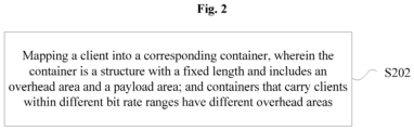
- Fig. 2 is a flowchart of a client mapping method according to some embodiments of the present disclosure, as shown in Fig. 2 , the flow includes the following operation S202.
- a client is mapped into a corresponding container, wherein the container is a structure with a fixed length and includes an overhead area and a payload area; and containers that carry clients within different bit rate ranges have different overhead areas.
- a client is mapped to a corresponding container having a structure with a fixed length, and the containers may correspondingly carry clients within different bit rate ranges according to different configured sizes of overhead areas, therefore, the solution provided in the embodiments of the present disclosure may solve the technical problem in the related art that containers cannot be configured for clients with different bit rates so as to compromise between overhead transmission periods and bandwidth utilization, and may achieve the effect of satisfying the requirements for the transmission periods of overhead fields with high real-time demands without increasing the transfer frequency for the overhead that has high real-time requirements.
- the client may be mapped into a small granularity container.
- the small granularity container is a frame structure with a fixed length, and contains two parts which are respectively an overhead area and a payload area.
- the size of the overhead area is able to be flexibly configured according to bit rates of the clients, i.e., for clients within (or with) different bit rate ranges, the size of the overhead area in the structure of the Optical Subscriber Unit (OSU) frame carrying the Optical Payload Unit (OPU) is different.
- OFSU Optical Subscriber Unit
- OU Optical Payload Unit
- the entity for performing the foregoing operation may be, but is not limited to, an optical transport network device, a base station, a computer second node, and the like.
- the overhead area in the operation S202 includes a basic overhead unit and a fixed number of extended overhead units, wherein the basic overhead unit is used for transmitting all overheads required by end-to-end monitoring of the client, the fixed number of extended overhead units are used for transmitting at least one overhead field of which a transmission period satisfies a preset condition, and the fixed number is a natural number and is determined according to a different bit rate range of the client. It may be understood that the fixed number may be 0 or a positive integer.
- the fixed number of extended overhead units include at least one of: a trail trace identifier overhead, an automatic protection switching overhead, and a container status indication overhead, wherein the container status indication overhead is used for indicating a status of the container.
- an overhead transmission period of the small granularity container is relatively slow, and a corresponding defect detection period is relatively long, and may not be able to satisfy an overhead transmission requirement with a high real-time requirement and related operation processing.
- the protection switching operation needs to be completed within a period of 50ms from the defect generation to the service recovery, which means that the overhead corresponding to the defect that triggers the alarm switching and the automatic protection switching overhead protocol need to be transmitted in a shorter period, therefore, it is necessary to increase the transmission frequency of the overhead with a high real-time requirement, such as automatic protection switching transmission protocol, and shorten the overhead transmission periods.
- the bandwidth utilization rate may be reduced by a certain extent, because the carried client is a low bit rate client, the reduction of the bandwidth utilization rate does not bring significant performance degradation experience.
- an overhead transmission period of the small granularity container is relatively fast, and a corresponding defect detection period is relatively short, so that an overhead transmission requirement with a high real-time requirement can be satisfied, and it is not necessary to increase the transmission frequency of the overhead with a high real-time requirement.
- the overhead area of the small granularity container (equivalent to the container in the embodiments of the present disclosure) into two parts: basic overhead unit(s) and extended overhead unit(s).
- the basic overhead unit is used for transmitting a set of all overheads for end-to-end monitoring of the client.
- the extended overhead unit is used for transmitting at least one overhead field having a high requirement for real-time performance.
- the at least one overhead field is a subset of end-to-end monitoring overheads, and includes one or more of a trail trace identifier overhead, an automatic protection switching overhead channel, and a small granularity container status indication overhead.
- the small granularity container status indication overhead is used for indicating a status of the small granularity container, wherein the status includes a normal status and a maintenance status, and the maintenance status includes an alarm indication signal, an open connection indication signal, and a locked indication signal.
- the clients that need to be supported are divided according to different bit rate ranges.
- a maximum bit rate in a high bit rate range is a maximum bit rate of the clients that need to be supported.
- the structure of the small granularity container is determined according to the high bit rate.
- the structure of the small granularity container includes an overhead area and a payload area.
- the overhead area includes a basic overhead unit.
- the structure of the small granularity container is able to satisfy the transmission period of the overhead with a high real-time requirement.
- an overhead field with a high real-time requirement and a corresponding transmission period are determined, and the number of required basic units is determined based on the number of overhead bytes carried by the basic overhead unit and the size of the overhead field, the transmission period of the basic unit is determined, and a minimum transmission period X of the basic unit therein is taken as a transmission period of the basic unit of the small granularity container.
- the different bit rate ranges include N bit rate ranges, wherein the fixed numbers of the extended overhead units in the containers that carry the clients within the different bit rate ranges are different, the fixed number of extended overhead units are evenly distributed in the container, and N is a positive integer greater than 1.
- a client in a first bit rate range of the N bit rate ranges may be configured with a basic overhead unit with a fixed size, wherein the first bit rate range is a maximum bit rate range of the N bit rate ranges.
- a basic overhead unit with a fixed size, a payload area, and one or more extended overhead units may be configured for a client in a bit rate range other than the first bit rate range among the N bit rate ranges.
- the fixed number of the extended overhead units need to be evenly distributed in the container.
- the container is constructed by using one basic overhead unit of 16 bytes and three extended overhead units of 16 bytes.
- the three extended overhead units may be spaced by 2304 payload bytes, that is, the three extended overhead units are evenly inserted into the current container to construct a new container structure.
- the different bit rate ranges include: a first bit rate range, and other bit rate ranges except the first bit rate range, i.e., a second bit rate range and a third bit rate range.
- a basic overhead unit with a fixed size is configured for a client within the first bit rate range;
- a basic overhead unit with a fixed size, a payload area with a first size, and one or more extended overhead units are configured for the client within the second bit rate range;
- a basic overhead unit with a fixed size, a payload area with a second size, and one or more extended overhead units are configured for the client within the third bit rate range, wherein the first size is greater than the second size.
- a minimum value of the first bit rate range is greater than or equal to a maximum value of the second bit rate range, and a minimum value of the second bit rate range is greater than or equal to a maximum value of the third bit rate range.
- clients may be divided into three groups according to bit rate ranges, a first group being clients with a high bit rate of 500Mbps - 1Gbps (equivalent to the above first bit rate range), a second group being clients with a medium bit rate 100Mbps - 500Mbps (equivalent to the above second bit rate range), and a third group being clients with a low bit rate 10Mbps - 100Mbps (equivalent to the above third bit rate range).
- the basic overhead unit has a size of 16 bytes, and is configured to transmit an overhead required by end-to-end monitoring of the client, wherein one byte is used for transmitting an Automatic Protection Switching (APS) and one byte is used for transmitting a status indication signal STAT.
- APS Automatic Protection Switching
- each basic overhead unit is 0.25ms.
- the transmission of STAT can be completed by one basic overhead unit, and since the transmission of the STAT needs to be completed within 1ms, the transmission period of each basic overhead unit is 1ms.
- the required minimum transmission period of the basic overhead unit is 0.25ms, in other words, the transmission of the overhead related to protection switching needs to be completed within 0.25ms.
- a method for implementing a small granularity container in which a structure of the small granularity container is determined as a fixed length, supported clients are divided according to their bit rate ranges, and then overhead areas with different sizes are configured according to different bit rate ranges, thereby satisfying a requirement for the transmission period of the overhead field with high real-time performance.
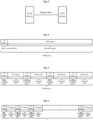
- Fig. 3 is a schematic diagram of a scenario where two OTN devices transmit a client signal through an OTN interface according to some embodiments of the present disclosure.
- the network architecture includes an OTN device 1, an OTN device 2, and an optical fiber.
- a connection is established between the OTN device 1 and the OTN device 2 via the optical fiber, and a data signal corresponding to a client is transmitted between the OTN device 1 and the OTN device 2.
- a supported client bit rate range is 10Mbps - 1Gbps.
- a client signal is transmitted between two OTN devices through an OTN interface, which specifically includes the following operations 1 to 5.
- clients are divided into three groups according to bit rate ranges, a first group being clients with a high bit rate of 500Mbps - 1Gbps, a second group being clients with a medium bit rate 100Mbps - 500Mbps, and a third group being clients with a low bit rate 10Mbps - 100Mbps.
- the size of a basic overhead unit is 16 bytes, and is configured to transmit an overhead required by end-to-end monitoring of a client.
- One byte of the basic overhead unit is used for transmitting an APS, and one byte of the basic overhead unit is used for transmitting a status indication signal (STAT).
- STAT status indication signal
- the APS includes 4 bytes in total, and four basic overhead units complete one APS protocol transmission.
- the transmission of the APS needs to be completed within 1ms, so that a transmission period of each basic overhead unit is 0.25ms.
- the STAT includes 1 byte in total, and one basic overhead unit completes one STAT transmission.
- the transmission of the STAT needs to be completed within 1ms, so that the transmission period of each basic overhead unit is 1ms.
- the required minimum transmission period of the basic overhead unit is 0.25ms, in other words, the transmission of the overhead related to protection switching needs to be completed within 0.25ms.
- the lowest bit rate in the high bit rate range is 500Mbps
- the minimum transmission period of the 16-byte basic overhead unit is 0.25ms
- the maximum length of the frame structure of the small granularity container is calculated to be 9375 bytes.
- Fig. 4 is a schematic structural diagram of a small granularity container corresponding to a client within a high bit rate range according to some embodiments of the present disclosure.
- the transmission period of the basic overhead unit of the small granularity container carrying 500Mbps client is: 9280*8/500 ⁇ 0.148ms, which satisfies the time period requirements of protection switching-related overhead transmission.
- Fig. 5 is a schematic structural diagram of a small granularity container corresponding to a client within a medium bit rate range according to some embodiments of the present disclosure.
- a Frame Alignment Signal (FAS) a Multi-frame Alignment Signal (MFAS), a status indication signal and an automatic protection switching protocol are carried in the extended overhead units, and the remaining fields of the extended overhead units can support user-defined settings, for example, the remaining fields of the extended overhead units may be used as a communication channel or used for transmitting synchronization information.
- FAS Frame Alignment Signal
- MFAS Multi-frame Alignment Signal
- a status indication signal and an automatic protection switching protocol are carried in the extended overhead units, and the remaining fields of the extended overhead units can support user-defined settings, for example, the remaining fields of the extended overhead units may be used as a communication channel or used for transmitting synchronization information.
- Fig. 6 is a schematic structural diagram of a small granularity container corresponding to a client within a low bit rate range according to some embodiments of the present disclosure.
- a Frame Alignment Signal (FAS) a Multi-frame Alignment Signal (MFAS), a status indication signal and an automatic protection switching protocol are carried in the extended overhead units, and the remaining fields of the extended overhead units can support user-defined settings, for example, the remaining fields of the extended overhead units may be used as a communication channel or used for transmitting synchronization information.
- FAS Frame Alignment Signal
- MFAS Multi-frame Alignment Signal
- a status indication signal and an automatic protection switching protocol are carried in the extended overhead units, and the remaining fields of the extended overhead units can support user-defined settings, for example, the remaining fields of the extended overhead units may be used as a communication channel or used for transmitting synchronization information.
- the client mapping method according to the foregoing embodiments may be implemented by software in addition to a necessary universal hardware platform, and definitely may also be implemented by hardware, however, in many cases, the former is a preferred implementation.
- the computer software product may be stored in a storage medium (such as a Read Only Memory (ROM)/Random Access Memory (RAM), a magnetic disk, and an optical disk), and may include several instructions for instructing a second node device (which may be a mobile phone), a computer, a server, a network device, or the like.
- the embodiments further provide a client mapping device, the client mapping device is used for implementing the described embodiments and exemplary implementations, and what has been described will not be elaborated.
- the term "module”, as used hereinafter, is a combination of software and/or hardware capable of realizing a predetermined function.
- the client mapping device described in the following embodiment is preferably implemented by software, implementation of hardware or a combination of software and hardware is also possible and conceived.
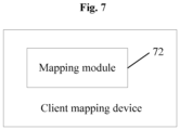
- Fig. 7 is a structural block diagram of a client mapping device according to some embodiments of the present disclosure.
- the client mapping device includes: a mapping module 72, configured to map a client into a corresponding container, wherein the container is a structure with a fixed length and includes an overhead area and a payload area; and containers that carry clients within different bit rate ranges have different overhead areas.
- a client is mapped to a corresponding container having a structure with a fixed length, and the containers may correspondingly carry clients within different bit rate ranges according to different configured sizes of overhead areas, therefore, the solution provided in the embodiments of the present disclosure may solve the technical problem in the related art that containers cannot be configured for clients with different bit rates so as to compromise between overhead transmission periods and bandwidth utilization, and may achieve the effect of satisfying the requirements for the transmission periods of overhead fields with high real-time demands without increasing the transfer frequency for the overhead that has high real-time requirements.
- the client may be mapped into a small granularity container.
- the small granularity container is a frame structure with a fixed length, and contains two parts which are respectively an overhead area and a payload area.
- the size of the overhead area is able to be flexibly configured according to bit rates of the clients, i.e., for clients within (or with) different bit rate ranges, the size of the overhead area in the structure of the Optical Subscriber Unit (OSU) frame carrying the Optical Payload Unit (OPU) is different.
- OFSU Optical Subscriber Unit
- OU Optical Payload Unit
- the overhead area of the mapping module 72 includes a basic overhead unit and a fixed number of extended overhead units, wherein the basic overhead unit is used for transmitting all overheads required by end-to-end monitoring of the client, the fixed number of extended overhead units are used for transmitting at least one overhead field of which a transmission period satisfies a preset condition, and the fixed number is a natural number and is determined according to a different bit rate range of the client.
- the fixed number of extended overhead units include at least one of: a trail trace identifier overhead, an automatic protection switching overhead, and a container status indication overhead, wherein the container status indication overhead is used for indicating a status of the container.
- an overhead transmission period of the small granularity container is relatively slow, and a corresponding defect detection period is relatively long, and may not be able to satisfy an overhead transmission requirement with a high real-time requirement and related operation processing.
- the protection switching operation needs to be completed within a period of 50ms from the defect generation to the service recovery, which means that the overhead corresponding to the defect that triggers the alarm switching and the automatic protection switching overhead protocol need to be transmitted in a shorter period, therefore, it is necessary to increase the transmission frequency of the overhead with a high real-time requirement, such as automatic protection switching transmission protocol, and shorten the overhead transmission periods.
- the bandwidth utilization rate may be reduced by a certain extent, because the carried client is a low bit rate client, the reduction of the bandwidth utilization rate does not bring significant performance degradation experience.
- an overhead transmission period of the small granularity container is relatively fast, and a corresponding defect detection period is relatively short, so that an overhead transmission requirement with a high real-time requirement can be satisfied, and it is not necessary to increase the transmission frequency of the overhead with a high real-time requirement.
- the overhead area of the small granularity container (equivalent to the container in the embodiments of the present disclosure) into two parts: basic overhead unit(s) and extended overhead unit(s).
- the basic overhead unit is used for transmitting a set of all overheads for end-to-end monitoring of the client.
- the extended overhead unit is used for transmitting at least one overhead field having a high requirement for real-time performance.
- the at least one overhead field is a subset of end-to-end monitoring overheads, and includes one or more of a trail trace identifier overhead, an automatic protection switching overhead channel, and a small granularity container status indication overhead.
- the small granularity container status indication overhead is used for indicating a status of the small granularity container, wherein the status includes a normal status and a maintenance status, and the maintenance status includes an alarm indication signal, an open connection indication signal, and a locked indication signal.
- the clients that need to be supported are divided according to different bit rate ranges.
- a maximum bit rate in a high bit rate range is a maximum bit rate of the clients that need to be supported.
- the structure of the small granularity container is determined according to the high bit rate.
- the structure of the small granularity container includes an overhead area and a payload area.
- the overhead area includes a basic overhead unit.
- the structure of the small granularity container is able to satisfy the transmission period of the overhead with a high real-time requirement.
- an overhead field with a high real-time requirement and a corresponding transmission period are determined, and the number of required basic units is determined based on the number of overhead bytes carried by the basic overhead unit and the size of the overhead field, the transmission period of the basic unit is determined, and a minimum transmission period X of the basic unit therein is taken as a transmission period of the basic unit of the small granularity container.
- the different bit rate ranges of the mapping module 72 include N bit rate ranges, wherein the fixed numbers of the extended overhead units in the containers that carry the clients within the different bit rate ranges are different, the fixed number of extended overhead units are evenly distributed in the container, and N is a positive integer greater than 1.
- a client in a first bit rate range of the N bit rate ranges may be configured with a basic overhead unit with a fixed size, wherein the first bit rate range is a maximum bit rate range of the N bit rate ranges.
- a basic overhead unit with a fixed size, a payload area, and one or more extended overhead units may be configured for a client in a bit rate range other than the first bit rate range among the N bit rate ranges.
- the fixed number of the extended overhead units need to be evenly distributed in the container.
- the container is constructed by using one basic overhead unit of 16 bytes and three extended overhead units of 16 bytes.
- the three extended overhead units may be spaced by 2304 payload bytes, that is, the three extended overhead units are evenly inserted into the current container to construct a new container structure.
- clients may be divided into three groups according to bit rate ranges, a first group being clients with a high bit rate of 500Mbps - 1Gbps (equivalent to the above first bit rate range), a second group being clients with a medium bit rate 100Mbps - 500Mbps (equivalent to the above second bit rate range), and a third group being clients with a low bit rate 10Mbps - 100Mbps (equivalent to the above third bit rate range).
- the basic overhead unit has a size of 16 bytes, and is configured to transmit an overhead required by end-to-end monitoring of the client, wherein one byte is used for transmitting an Automatic Protection Switching (APS) and one byte is used for transmitting a status indication signal STAT.
- APS Automatic Protection Switching
- each basic overhead unit is 0.25ms.
- the transmission of STAT can be completed by one basic overhead unit, and since the transmission of the STAT needs to be completed within 1ms, the transmission period of each basic overhead unit is 1ms.
- the required minimum transmission period of the basic overhead unit is 0.25ms, in other words, the transmission of the overhead related to protection switching needs to be completed within 0.25ms.
- each module may be implemented by software or hardware, the latter may be implemented in the following manner, but is not limited thereto: all the modules are located in a same processor; alternatively, the modules are located in different processors in an arbitrary combination.
- the embodiments of the present disclosure also provide a computer readable storage medium, the computer readable storage medium stores a computer program, wherein the computer program, when running on a processor, causes the processor to execute the operations in any one of the described method embodiments.
- the computer readable storage medium may include, but is not limited to, any medium that can store a computer program, such as a Universal Serial Bus (USB) flash drive, a Read Only Memory (ROM), a Random Access Memory (RAM), a removable hard disk, a magnetic disk, or an optical disc.
- USB Universal Serial Bus
- ROM Read Only Memory
- RAM Random Access Memory
- the embodiments of the present disclosure further provide an electronic device, including a memory and a processor, the memory stores a computer program, and the processor is configured to run the computer program to execute operations in any one of the method embodiments.
- the electronic device may further include a transmission device and an input/output device, wherein the transmission device is connected to the processor, and the input/output device is connected to the processor.
- each module or each operation of the present disclosure can be implemented by a universal computing device, they may be centralized on a single computing device or distributed on a network composed of a plurality of computing devices, they can be implemented by program codes executable by a computing apparatus, and thus can be stored in a storage apparatus and executed by the computing apparatus. Furthermore, in some cases, the shown or described operations may be executed in an order different from that described here, or they are made into integrated circuit modules respectively, or a plurality of modules or operations therein are made into a single integrated circuit module for implementation. As such, the present disclosure is not limited to any particular hardware and software combination.
Landscapes
- Engineering & Computer Science (AREA)
- Computer Networks & Wireless Communication (AREA)
- Signal Processing (AREA)
- Computer Hardware Design (AREA)
- General Engineering & Computer Science (AREA)
- Computer Security & Cryptography (AREA)
- Computer And Data Communications (AREA)
- Data Exchanges In Wide-Area Networks (AREA)
- Time-Division Multiplex Systems (AREA)
Applications Claiming Priority (2)
| Application Number | Priority Date | Filing Date | Title |
|---|---|---|---|
| CN202210739126.5A CN117354646A (zh) | 2022-06-27 | 2022-06-27 | 客户业务的映射方法及装置、存储介质及电子装置 |
| PCT/CN2023/071389 WO2024001158A1 (fr) | 2022-06-27 | 2023-01-09 | Procédé et dispositif de mappage de service de client, support de stockage et dispositif électronique |
Publications (2)
| Publication Number | Publication Date |
|---|---|
| EP4531422A1 true EP4531422A1 (fr) | 2025-04-02 |
| EP4531422A4 EP4531422A4 (fr) | 2025-10-01 |
Family
ID=89359949
Family Applications (1)
| Application Number | Title | Priority Date | Filing Date |
|---|---|---|---|
| EP23829351.8A Pending EP4531422A4 (fr) | 2022-06-27 | 2023-01-09 | Procédé et dispositif de mappage de service de client, support de stockage et dispositif électronique |
Country Status (3)
| Country | Link |
|---|---|
| EP (1) | EP4531422A4 (fr) |
| CN (1) | CN117354646A (fr) |
| WO (1) | WO2024001158A1 (fr) |
Families Citing this family (1)
| Publication number | Priority date | Publication date | Assignee | Title |
|---|---|---|---|---|
| CN118945725A (zh) * | 2024-06-27 | 2024-11-12 | 中国移动通信有限公司研究院 | 一种传输方法、装置、存储介质、程序产品和设备 |
Family Cites Families (6)
| Publication number | Priority date | Publication date | Assignee | Title |
|---|---|---|---|---|
| US6891855B2 (en) * | 2000-07-27 | 2005-05-10 | Corrigent Systems, Ltd. | Dynamic packet fragmentation |
| CN107566074B (zh) * | 2016-06-30 | 2019-06-11 | 华为技术有限公司 | 光传送网中传送客户信号的方法及传送设备 |
| CN110830143B (zh) * | 2018-08-13 | 2022-03-25 | 中兴通讯股份有限公司 | 一种业务传输方法及装置、光传送网设备、存储介质 |
| CN111740801B (zh) * | 2019-03-25 | 2021-12-10 | 华为技术有限公司 | 一种业务数据的处理方法及装置 |
| CN111740782B (zh) * | 2019-03-25 | 2023-03-10 | 华为技术有限公司 | 一种业务数据的处理方法及装置 |
| CN114554320B (zh) * | 2020-11-26 | 2024-11-08 | 中国移动通信有限公司研究院 | 一种光网络业务发送、接收方法、设备及存储介质 |
-
2022
- 2022-06-27 CN CN202210739126.5A patent/CN117354646A/zh active Pending
-
2023
- 2023-01-09 WO PCT/CN2023/071389 patent/WO2024001158A1/fr not_active Ceased
- 2023-01-09 EP EP23829351.8A patent/EP4531422A4/fr active Pending
Also Published As
| Publication number | Publication date |
|---|---|
| EP4531422A4 (fr) | 2025-10-01 |
| WO2024001158A1 (fr) | 2024-01-04 |
| CN117354646A (zh) | 2024-01-05 |
Similar Documents
| Publication | Publication Date | Title |
|---|---|---|
| US12452347B2 (en) | Communication method, communications device, and storage medium | |
| JP6985430B2 (ja) | 制御情報伝送方法およびデバイス | |
| JP7779489B2 (ja) | 探索空間モニタリング方法及び装置 | |
| EP2624628A1 (fr) | Procédé de configuration de l'intervalle entre mesures, terminal et dispositif de réseau | |
| US12483370B2 (en) | Method for monitoring control channels and determining transmission configuration indication, and terminal | |
| US11750310B2 (en) | Clock synchronization packet exchanging method and apparatus | |
| CN110612761B (zh) | 带宽分段的配置方法及网络设备、终端 | |
| CN108521343A (zh) | 一种oam报文的处理方法及装置 | |
| EP4589918A1 (fr) | Procédé et appareil de communication | |
| WO2022042743A1 (fr) | Procédé et appareil de transmission de données, dispositif électronique et support lisible par ordinateur | |
| US11381335B2 (en) | Method and apparatus for spectrum defragmentation, device, and system | |
| US20220264340A1 (en) | Method and device for determining dynamic harq-ack codebook | |
| WO2021036375A1 (fr) | Procédé et appareil de communication | |
| EP4531422A1 (fr) | Procédé et dispositif de mappage de service de client, support de stockage et dispositif électronique | |
| CN112087292B (zh) | 一种信道状态测量参数指示方法及装置 | |
| US10869222B2 (en) | Data frame transmission method and apparatus for virtual elastic CPRI interface | |
| CN113905399B (zh) | 一种时延处理方法、设备、装置及介质 | |
| EP3618317A1 (fr) | Procédé d'envoi de messages et procédé et appareil de réception de messages | |
| EP4468631A1 (fr) | Procédé de transmission de données, appareil de communication par courants porteurs en ligne et système | |
| WO2024040884A1 (fr) | Procédé, appareil et système de traitement de service | |
| EP3800831A1 (fr) | Procédé et appareil de configuration de groupe de liaisons | |
| CN114531215B (zh) | 一种数据传输方法、装置、存储介质及电子装置 | |
| CN113795047B (zh) | 一种下行节能方法、系统、计算机设备和存储介质 | |
| CN109639713A (zh) | 一种iq数据帧和传输、接收方法 | |
| CN116584078B (zh) | 用于移动通信系统的方法和设备 |
Legal Events
| Date | Code | Title | Description |
|---|---|---|---|
| STAA | Information on the status of an ep patent application or granted ep patent |
Free format text: STATUS: THE INTERNATIONAL PUBLICATION HAS BEEN MADE |
|
| PUAI | Public reference made under article 153(3) epc to a published international application that has entered the european phase |
Free format text: ORIGINAL CODE: 0009012 |
|
| STAA | Information on the status of an ep patent application or granted ep patent |
Free format text: STATUS: REQUEST FOR EXAMINATION WAS MADE |
|
| 17P | Request for examination filed |
Effective date: 20241223 |
|
| AK | Designated contracting states |
Kind code of ref document: A1 Designated state(s): AL AT BE BG CH CY CZ DE DK EE ES FI FR GB GR HR HU IE IS IT LI LT LU LV MC ME MK MT NL NO PL PT RO RS SE SI SK SM TR |
|
| REG | Reference to a national code |
Ref country code: DE Ref legal event code: R079 Free format text: PREVIOUS MAIN CLASS: H04Q0011000000 Ipc: H04J0003160000 |
|
| A4 | Supplementary search report drawn up and despatched |
Effective date: 20250902 |
|
| DAV | Request for validation of the european patent (deleted) | ||
| DAX | Request for extension of the european patent (deleted) | ||
| RIC1 | Information provided on ipc code assigned before grant |
Ipc: H04J 3/16 20060101AFI20250827BHEP |