EP4531426A1 - Wasserdichte schall- und vibrationserfassungsvorrichtung - Google Patents
Wasserdichte schall- und vibrationserfassungsvorrichtung Download PDFInfo
- Publication number
- EP4531426A1 EP4531426A1 EP24201590.7A EP24201590A EP4531426A1 EP 4531426 A1 EP4531426 A1 EP 4531426A1 EP 24201590 A EP24201590 A EP 24201590A EP 4531426 A1 EP4531426 A1 EP 4531426A1
- Authority
- EP
- European Patent Office
- Prior art keywords
- air volume
- housing
- closed air
- vibration
- pcba
- Prior art date
- Legal status (The legal status is an assumption and is not a legal conclusion. Google has not performed a legal analysis and makes no representation as to the accuracy of the status listed.)
- Pending
Links
Images


Classifications
-
- H—ELECTRICITY
- H04—ELECTRIC COMMUNICATION TECHNIQUE
- H04R—LOUDSPEAKERS, MICROPHONES, GRAMOPHONE PICK-UPS OR LIKE ACOUSTIC ELECTROMECHANICAL TRANSDUCERS; ELECTRIC HEARING AIDS; PUBLIC ADDRESS SYSTEMS
- H04R1/00—Details of transducers, loudspeakers or microphones
- H04R1/08—Mouthpieces; Microphones; Attachments therefor
- H04R1/083—Special constructions of mouthpieces
-
- G—PHYSICS
- G01—MEASURING; TESTING
- G01H—MEASUREMENT OF MECHANICAL VIBRATIONS OR ULTRASONIC, SONIC OR INFRASONIC WAVES
- G01H11/00—Measuring mechanical vibrations or ultrasonic, sonic or infrasonic waves by detecting changes in electric or magnetic properties
- G01H11/06—Measuring mechanical vibrations or ultrasonic, sonic or infrasonic waves by detecting changes in electric or magnetic properties by electric means
- G01H11/08—Measuring mechanical vibrations or ultrasonic, sonic or infrasonic waves by detecting changes in electric or magnetic properties by electric means using piezoelectric devices
-
- B—PERFORMING OPERATIONS; TRANSPORTING
- B81—MICROSTRUCTURAL TECHNOLOGY
- B81B—MICROSTRUCTURAL DEVICES OR SYSTEMS, e.g. MICROMECHANICAL DEVICES
- B81B3/00—Devices comprising flexible or deformable elements, e.g. comprising elastic tongues or membranes
- B81B3/0018—Structures acting upon the moving or flexible element for transforming energy into mechanical movement or vice versa, i.e. actuators, sensors, generators
- B81B3/0021—Transducers for transforming electrical into mechanical energy or vice versa
-
- G—PHYSICS
- G01—MEASURING; TESTING
- G01H—MEASUREMENT OF MECHANICAL VIBRATIONS OR ULTRASONIC, SONIC OR INFRASONIC WAVES
- G01H3/00—Measuring characteristics of vibrations by using a detector in a fluid
- G01H3/005—Testing or calibrating of detectors covered by the subgroups of G01H3/00
-
- B—PERFORMING OPERATIONS; TRANSPORTING
- B81—MICROSTRUCTURAL TECHNOLOGY
- B81B—MICROSTRUCTURAL DEVICES OR SYSTEMS, e.g. MICROMECHANICAL DEVICES
- B81B2201/00—Specific applications of microelectromechanical systems
- B81B2201/02—Sensors
- B81B2201/0257—Microphones or microspeakers
-
- H—ELECTRICITY
- H04—ELECTRIC COMMUNICATION TECHNIQUE
- H04R—LOUDSPEAKERS, MICROPHONES, GRAMOPHONE PICK-UPS OR LIKE ACOUSTIC ELECTROMECHANICAL TRANSDUCERS; ELECTRIC HEARING AIDS; PUBLIC ADDRESS SYSTEMS
- H04R1/00—Details of transducers, loudspeakers or microphones
- H04R1/02—Casings; Cabinets ; Supports therefor; Mountings therein
- H04R1/04—Structural association of microphone with electric circuitry therefor
-
- H—ELECTRICITY
- H04—ELECTRIC COMMUNICATION TECHNIQUE
- H04R—LOUDSPEAKERS, MICROPHONES, GRAMOPHONE PICK-UPS OR LIKE ACOUSTIC ELECTROMECHANICAL TRANSDUCERS; ELECTRIC HEARING AIDS; PUBLIC ADDRESS SYSTEMS
- H04R1/00—Details of transducers, loudspeakers or microphones
- H04R1/08—Mouthpieces; Microphones; Attachments therefor
- H04R1/083—Special constructions of mouthpieces
- H04R1/086—Protective screens, e.g. all weather or wind screens
-
- H—ELECTRICITY
- H04—ELECTRIC COMMUNICATION TECHNIQUE
- H04R—LOUDSPEAKERS, MICROPHONES, GRAMOPHONE PICK-UPS OR LIKE ACOUSTIC ELECTROMECHANICAL TRANSDUCERS; ELECTRIC HEARING AIDS; PUBLIC ADDRESS SYSTEMS
- H04R2499/00—Aspects covered by H04R or H04S not otherwise provided for in their subgroups
- H04R2499/10—General applications
- H04R2499/13—Acoustic transducers and sound field adaptation in vehicles
Definitions
- the present disclosure relates to a sound and vibration sensing device and more particularly, to a waterproof sound and vibration sensing device.
- sensing devices are being positioned on an exterior surface structure (e.g., body panel, frame, glass) of the vehicle that is directly exposed to various types of harsh environmental conditions.
- the sensing devices must withstand usage of the vehicle in many scenarios, including but not limited to, exposure to water and moisture, high-temperature/high-pressure water jet, ice, dust, debris, and mud.
- a sound and vibration sensing device comprising a housing, a printed circuit board assembly (PCBA) having an aperture, the PCBA is supported inside the housing, a sensor element on the PCBA mounted over the aperture, a structural membrane that is flexible and non-porous, the structural membrane having first and second surfaces, the structural membrane being arranged to seal the housing at one end, a first closed air volume below the sensor element, the first closed air volume is defined inside the housing under the aperture between the PCBA and the structural membrane, and a second closed air volume above the sensor element, the second closed air volume is defined inside the housing between the housing and the PCBA, wherein the sensor element measures changes in air pressure in the first closed air volume caused by vibration of the structural membrane induced by external acoustic pressure and structural vibration to output a combined sound and vibration signal.
- PCBA printed circuit board assembly
- the sound and vibration sensing device has a leak channel in the PCBA that connects the first closed air volume to the second closed air volume to filter a low frequency vibration signal.
- the size of the leak channel is dependent upon a predetermined frequency response shape, an attenuation amount, and a predetermined frequency range of the sound and vibration sensing device.
- the sound and vibration sensing device a support structure in the housing, the support structure having first and second surfaces and an aperture therethrough that aligns with the aperture in the PCBA, the first surface of the support structure faces into the first closed air volume and the second surface of the support structure faces into the second closed air volume, the PCBA is supported by the support structure.
- the sound and vibration sensing device has a leak channel in the PCBA and the support structure that connects the first closed air volume with the second closed air volume to filter a low frequency vibration signal.
- the sound and vibration sensing device has a mechanical stop on the first surface of the support structure.
- the support structure is cone-shaped.
- a damping layer is positioned on the first surface of the structural membrane.
- a damping layer is positioned on the second surface of the structural membrane.
- the structural membrane has a footing around the second surface, the footing attaches to a bottom surface of the housing to seal the housing and to support the PCBA inside the housing .
- the sensor element is a MEMS microphone having a first aperture that vents into the first closed air volume and a second aperture that vents into the second closed air volume.
- the sound and vibration sensing device has a second sensor element on the PCBA for simultaneously sensing sound and vibration for the combined sound and vibration output signal.
- FIG. 1 is a schematic of a sound and vibration sensing device 100 according to one or more embodiments.
- a housing 102 has an opening 104 at one end.
- a support structure 106 is attached in a sealed manner inside the housing 102 at the opening 104.
- a structural membrane 108 is attached in a sealed manner to the support structure 106 and/or the housing 102 in such a way that there are no openings to the environment external to the housing 102.
- the housing 102 of the sound and vibration sensing device 100 may be mounted and mechanically fixed to a base structure, not shown in FIG. 1 , which may be, for example, a body panel, vehicle frame, glass surface of a vehicle.
- a first surface 110 of the structural membrane 108 is exposed to an outside environment, external to the housing 102.
- a second surface 112 of the structural membrane 108 is internal to the housing 102.
- the sealed manner of attachment among the housing 102, the support structure 106, and the structural membrane 108 defines a first closed air volume, V1, inside the housing 102 between the second surface 112 of the structural membrane 108 and a first surface 114 of the support structure 106.
- the use of "closed" in relation to the first closed air volume refers to V1 being closed-off from the environment external to the housing 102.
- a second closed air volume, V2 is defined between the housing 102 and a second surface 116 of the support structure 106.
- Vibration (e.g., acceleration) input 111 is transmitted via the support structure 106.
- the sound and vibration sensing device 100 may attach to the base structure by way of the housing 102.
- Structural vibration (e.g., acceleration) input 111 from the base structure may also be transmitted to the support structure 106 by way of the housing 102, causing the structural membrane 108 to flex.
- a printed circuit board (PCB) 118 is mounted to the second surface 116 of the support structure 106.
- a sensor element 120 is placed on the PCB 118.
- the sensor element 120 may be, for example, a microphone device such as a micro-electro-mechanical system (MEMS) microphone device, or an electret condenser microphone (ECM) device.
- MEMS micro-electro-mechanical system
- ECM electret condenser microphone
- Other circuit components (not shown in FIG. 1 ) that are necessary for the sensor element 120 to function properly may also be placed on the PCB 118.
- the PCB 118, the sensor element 120, and any other necessary components on the PCB 118 are referred to as a PCB assembly (PCBA).
- PCBA PCB assembly
- the first surface 110 of the structural membrane 108 is exposed to the outside environment.
- the housing 102 is sealed by the structural membrane 108.
- the structural membrane 108 and the support structure 106 define the closed air volume, V1.
- Materials and configurations of the seal created between the housing 102, the support structure 106, and the structural membrane 108 may vary based on design criteria so long as the attachment of elements creates a seal between the structural membrane 108 and the support structure 106 to define the first closed air volume V1 and to protect the sensor element 120 from contaminants.
- An aperture, or port hole, 122 in the PCB 118 and the support structure 106 opens the first closed air volume, V1, to the sensor element 120.
- the sensor element e.g., a MEMS microphone or ECM
- the vibration motion of the structural membrane 108 may also be induced by the base structural vibration input 111.
- the sensor element 120 may be either a bottom-port MEMS or a top-port MEMS microphone so long as the port hole 122 is open to the first closed air volume, V1.
- the structural membrane 108 is not an acoustic membrane or mesh typically used to protect microphones from foreign contamination.
- the structural membrane 108 is a structurally durable membrane made of a solid material, for example, engineering plastic or metal.
- the structural membrane 108 is not only non-porous to liquids and dust, but also air.
- FIG. 2 is a lumped-parameter model 200 that represents how the structural membrane 108 vibrates under external excitations.
- the structural membrane 108 is represented as a mass, m s , supported on the support structure (not shown in FIG. 2 ) and/or the housing 102.
- a first spring, k s represents the structural spring stiffness of the structural membrane 108.
- a second, parallel spring, k a represents the air spring stiffness of the first closed air volume, V1. Structural damping of the structural membrane 108, is represented by parameter, c s .
- vibration e.g., in the forms of displacement, velocity, and acceleration
- structural vibration input 111 may be transmitted to the support structure 106 (not shown in FIG. 2 ) through the housing 102 leading to vibration energy being transmitted directly to the structural membrane 108 that is attached to the support structure 106 and/or the housing 102.
- a displacement amplitude, d, of the structural membrane 108 to unit input may be controlled by a total stiffness, ( k s + k a ) .
- a measurement bandwidth of the sensor element 120 may be determined by a resonance frequency of this mass-spring vibration system and is proportional to a square root of the ratio of a total stiffness, ( k s + k a ) , to an effective mass of the structural membrane, m s .
- a peak displacement amplitude at the resonance frequency is mainly determined by the structural damping, c s of the structural membrane 108.
- the sensor element 120 e.g., a MEMS microphone or ECM
- the acoustic pressure generated due to volume change in the air cavity is proportional to an area of the structural membrane and the membrane displacement, but inversely proportional to the closed air volume.
- the material of the structural membrane may be a thin sheet, or sheets, of plastic, polymer, or metal such as acrylonitrile butadiene styrene (ABS), polybutylene terephthalate (PBT), nylon, and/or aluminum, etc.
- FIG. 3 shows a measured frequency response 300 of one or more embodiments of the waterproof sound and vibration sensor shown in FIG. 1 .
- Curve 302 is the response amplitude normalized to the 1 kHz sensitivity of a direct measurement of a MEMS microphone element without a structural membrane.
- Curve 304 in comparison, is a 0.1 mm thick aluminum structural membrane.
- a height, h, and a diameter, D, (see FIG. 1 ) of the first closed air volume, V1 is 0.5 mm and 25 mm, respectively. This example design leads to a closed air volume, V1, of approximately 245 mm 3 .
- curve 302 shows that the frequency response of curve 302, without a structural membrane, has the highest sensitivity and the widest effective measurement bandwidth of the sensor element, as represented by the flat portion of the curve 302.
- curve 304 shows that the sensitivity is reduced slightly (about 1 dB reduction at 1 kHz), and the bandwidth narrows to about 4 kHz.
- the sensitivity is slightly more reduced (about 2.5 dB reduction at 1 kHz), and the bandwidth further narrows as well.
- the choice of material for the structural membrane will be dependent upon meeting targeted environmental protection requirements as well as the sensitivity and bandwidth requirements.
- a range of the diameter for the structural membrane 108 may be between 10-35 mm.
- the thickness of the structural membrane may have a range, for example, between 0.2-0.8 mm for plastic or polymer materials and 0.02-0.2 mm for metallic materials.
- the acoustic pressure generated in the closed air volume, V1, caused by the displacement of the structural membrane 108, is inversely proportional to V1.
- An effective way to increase sensitivity, and subsequently signal-to-noise ratio (SNR), is to minimize the volume of V1. Therefore, the height, h , of the first sealed air volume, V1, may be as small as practically allowable to minimize the enclosed air volume.
- An example range may be 0.1-1 mm.
- the total mass of the structural membrane 108 may be, for example, two to three orders of magnitude higher than a membrane that is part of a MEMS microphone or ECM sensor element 120. It should be noted that the ranges described herein are for example purposes only. One skilled in the art is capable of understanding that a microphone sensitivity to vibration input transmitted from a base structure in the housing is proportional to the structural membrane mass, so that the waterproof sound and vibration sensor described herein, with a closed housing and a structural membrane, is more sensitive to a vibration input when compared to a traditional microphone element (e.g., MEMS microphone or ECM).
- a traditional microphone element e.g., MEMS microphone or ECM
- vibration sensitivity of the one or more embodiments described herein is advantageous because the sensor effectively measures both and outputs a combined signal.
- sound-sensing microphone design often calls for minimizing vibration-sensing sensitivity.
- structural vibrations are located mostly at low frequencies (e.g., ⁇ 300-500 Hz) while acoustic input is broadband up to 10 kHz or higher. Therefore, incorporating a high-pass filter will filter low frequency vibrations out of the sensor output signal.
- a larger effective volume may be accomplished by including the second closed volume, V2 to be seen by the sensor element 120.
- the first closed volume V1 and the second closed volume V2 may be connected by an optional leak channel 124.
- Low frequency sensitivity of the waterproof sound and vibration sensing device 100 may be attenuated by controlling the size of V2 in relation to V1. For example, when V2 is significantly larger (e.g., on the order of 10 times) than V1, low frequency sensitivity can be attenuated by approximately 7-12 dB as shown in FIG. 4 , which shows simulated results of the frequency response amplitude normalized at 1kHz.
- an attenuation amount, and a frequency range, within which the sensitivity is to be attenuated may be adjusted by adjusting a size of leak channel 124 which modifies the size of V2 in relation to V1.
- the curve 402 shows a frequency response for a leak channel having a 0.1mm diameter.
- the curve 404 shows a frequency response for a leak channel having a diameter of 0.2mm.
- the curve 406 shows a frequency response for a leak channel having a diameter of 0.3mm.
- the curve 408 shows a frequency response for a leak channel having a diameter of 0.4mm which shows how the low frequency sensitivity is attenuated by approximately 12 dB.
- sensitivity to vibration input is attenuated and sensitivity to acoustic input is attenuated. This may be desirable in some applications when an acoustic input above 300-500 Hz is the desired signal to be measured with an environmentally sealed sound and vibration sensor. In such applications, low frequency signals that contain the most vibration energy may be sensed by a separate, dedicated, vibration sensing element, such as an accelerometer.
- a displacement amplitude of the structural membrane 108 may be induced by dynamic base vibration 111 and acoustic excitation 109 applied on the structural membrane 108, or external force directly applied to the first surface 110 of the structural membrane 108 (see FIG. 1 ).
- the resulting displacement amplitude corresponding to the dynamic base vibration or acoustic excitation may be on the order of tens to hundreds of micrometers, which is relatively small. However, under large external force inputs, such as the force that might be applied directly to the structural membrane surface under high pressure water spray, the resulting displacement (or deformation) amplitude could be much larger. Large displacement/deformation introduces stress on the material that may, undesirably, alter the mechanical properties of the structural membrane 108 or even cause damage rendering the sensor inoperable.
- FIG. 5 shows one or more embodiments of a sound and vibration sensing device 500 that incorporates a mechanical stop 502 into the support structure 106 to prevent the structural membrane 108 from deforming excessively under large external force inputs.
- the mechanical stop 502 is located on the first surface 114 of the support structure 106. When the structural membrane 108 is exposed to an external force that causes a large displacement, the displacement/deformation of the structural membrane 108 will be limited by the mechanical stop 502 thereby preventing it from being overstressed.
- An additional advantage of the mechanical stop 502 may be realized by using a design, or pattern, of the mechanical stop 502 to help increase the sensitivity of the sound and vibration sensing device 500.
- the structure of the mechanical stop 502 may be implemented in a manner that consumes some of the closed volume V1.
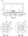
- FIG. 6A shows one example of many in which a pattern 600A of distributed bumps 602 creates the mechanical stop.
- FIG. 6B shows another example of many possible patterns 600B in which rings 604 are concentrically distributed to create the mechanical stop.
- a damping layer 702 may be added to the structural membrane 108 to attenuate a resonance peak amplitude of the frequency response curve.
- the damping layer 702 may be a viscoelastic coating, e.g., rubber, or other suitable material.
- the damping layer 702 may be added to, or may be an alternative to, the mechanical stop 502.
- the damping layer 702 may be added to the first 110, second 112, or first 110 and second 112, surfaces of the structural membrane 108.
- the damping layer 702 applied to the second surface 112 of the structural membrane 108 will take up space consuming volume in the closed volume V1, thereby improving the acoustic performance by increasing the sensitivity of the sound and vibration sensing device 700.
- the damping layer 702 is applied to the first surface 110 of the structural membrane 108.
- the damping layer 702 When the damping layer 702 is applied to the first surface 110 of the structural membrane 108, it adds additional protection from environmental contamination that may cause damage to the sensor components.
- FIG. 9 shows one or more embodiments of a sound and vibration sensing device 900 having a bottom port MEMS microphone element 902.
- the bottom port MEMS microphone element 902 has a MEMS sensing element 908.
- a first port hole 904 on the bottom of the MEMS sensing element 908 connects an air volume 909 in front of the MEMS microphone element 902 to the closed air volume, V1.
- a second aperture, or port hole 906, vents an air volume 910 behind the MEMS sensing element 908 to the closed air volume V2.
- a hybrid waterproof sound and vibration sensing device 1000 is shown.
- An accelerometer 1002 e.g., a MEMS accelerometer sensor
- the accelerometer 1002 has an output that is independent of the sound sensing sensor element 120 (MEMS microphone or ECM, for example).
- the leak channel 124 connects the closed air volume V1 and closed air volume V2 in a manner that configures the sensor element 120 to be insensitive to low frequency vibration and acoustic excitations (see discussion above with reference to FIG. 4 ).
- the leak channel 124 has no impact on the accelerometer 1002 as the accelerometer 1002 directly measures the base structure vibration input 111 transmitted to the support structure 106 and the PCB 118 through the housing 102 regardless of the displacement amplitude of the structural membrane 108 or a volume change of the closed air volume, V1.
- Incorporating the accelerometer 1002 provides simultaneous sound and vibration sensing for vibration input of interest at low frequencies (e.g., ⁇ 350 Hz) and acoustic input of interest at frequencies higher than, for example, 350 Hz.
- the sensor element 120 is entirely sealed from the external environment. While this is ideal for protecting the sensor from the environment, unwanted static pressure may build up inside the first and second closed air volumes, V1, V2. Static pressure build up may occur when there are differences in temperature between the environment and the sealed space inside the first and second closed air volumes. Static pressure may also be caused by changes in altitude.
- a waterproof sound and vibration sensor 1100 has a vent, or ventilation hole 1102, in the housing 102.
- a dense acoustic mesh layer 1104 covers the ventilation hole 1102 from within the housing 102.
- the ventilation hole 1102 is sized as small as possible and only large enough as necessary for equalizing the static pressure between the inside of the housing 102 and the external environment.
- the ventilation hole 1102 may be less than 1 mm in diameter.
- the ventilation hole 1102 is preferably positioned at a location in the housing 102 as far from the sensor element 120 as possible.
- the dense acoustic mesh layer 1104 may be thick enough to protect the interior of the housing 102 from the external environment with a high flow resistance, while still allowing for equalized pressure between the inside and the outside of the housing 102.
- the dense acoustic mesh layer 1104 may be made of expanded Polytetrafluoroethylene (ePTFE) material on the order of 0.1 to 0.5 mm in thickness.
- ePTFE expanded Polytetrafluoroethylene
- the sensitivity and the SNR of the sound and vibration sensing device 1200 is improved by reducing the first sealed volume, V1. This may be accomplished by altering the configuration of the supporting structure 1206 in a manner that reduces the size of the first sealed volume, V1.
- the example shown in FIG. 12 has a configuration for the support structure 1206 that is cone-shaped, which defines a smaller first sealed volume, V1 than the exemplary flat disk-shaped support structure 116 shown in FIG. 11 .
- a separate support structure is not included inside the waterproof sound and vibration sensing device 1300.
- the PCB 1318 attaches to the housing 1302 and may be positioned as close as possible to the structural membrane 1308.
- the sound and vibration sensing device 1400 has a structural membrane 1408 that, instead of being recessed in, and attached to, one end of the housing 1402 (as shown in FIGS. 1 , 5 , 7 , and 9-10 ), the structural membrane 1408 attaches to at one end of the housing 1402 so that it may also function as the support structure.
- the structural membrane 1408 may be a one-piece configuration with a footing member 1430.
- the footing member 1430 attaches directly to an outer perimeter 1432 of the housing 1402.
- the PCB 118 is attached inside the housing 1402 and is supported by the footing member 1430 of the structural membrane 1408.
- the first surface 1410 of the structural membrane 1408, the surface that is exposed to the external environment, may be a smooth surface to help reduce wind turbulence effect, which is particularly beneficial when the waterproof sound and vibration sensor 1400 is used on a base structure such as a vehicle exterior.
- the sound and vibration sensing device has a closed body that is entirely sealed from the external environment.
- the structural membrane 108, 1408 is mechanically flexible and vibrates under external sound or vibration excitations.
- the sensor element 120 which may be a microphone (MEMS, ECM, etc.), an accelerometer, or both, measures the acoustic pressure inside the first closed air volume, V1 by the vibration of the structural membrane 108, 1408.
- the waterproof sound and vibration sensing device described above has many features that may be used alternatively or additionally making the device configurable for many applications.
- FIG. 15 shows a method for determining and/or selecting which features should be incorporated into the sensing device based on a set of goals associated with a particular application for the sensing device.
- Electroacoustic goals are set.
- Electroacoustic goals may include sensitivity and bandwidth requirements for the use of the sensing device. For example, detecting an emergency vehicle siren, road noise cancellation, and voice command detection.
- a material for the structural membrane is selected based on the environmental goals.
- the structural membrane may be, for example, in the shape of thin sheets made of engineering plastics, polymers, and metal materials, such as ABS, PBT, Nylon, Aluminum, etc.
- the structural membrane material should be chosen to first meet the targeted environmental protection requirements, then to provide the best possible sensitivity and bandwidth.
- a membrane size (diameter or area) and thickness are selected based on the electroacoustic goals. Assuming a circular shaped structural membrane and housing, an exemplary range of membrane diameters may be between 10 and 35 mm. An exemplary range of membrane thickness may be 0.2 to 0.8 mm for plastic/polymer materials and 0.02 to 0.2 mm for metallic materials.
- the first closed volume, V1 is determined based on the electroacoustic goals.
- the height, h, of the first closed air volume, V1 should be as small as practically allowable to minimize the first enclosed air volume, V1. For example, in the range of 0.1 mm to 1 mm. Also, it should be noted that the first closed air volume, V1, may also be affected by the configuration of the support structure.
- the second closed volume, V2 is determined based on the first closed volume, V1.
- the second closed volume, V2, is preferably larger than the first closed volume, V1.
- V2 may be on the order of ten times larger than V1.
- step 1514 the size and shape of the closed housing to contain V1 and V2 is determined.
- a determination about whether high pass filtering is needed for the specific application of the sound and vibration sensing device is needed 1518, a leak channel is incorporated 1520 between V1 and V2.
- the size of the leak channel is determined based on the electroacoustic goals such as desired sensitivity and bandwidth.
- the configuration of the structural membrane may be combined with a housing that is vented to the external environment.
- the waterproof sound and vibration sensor may incorporate a port hole and a leak channel, or no leak channel.
- the waterproof sound and vibration sensor may include a leak channel and a vented housing, or no leak channel and a vented housing.
Landscapes
- Physics & Mathematics (AREA)
- General Physics & Mathematics (AREA)
- Engineering & Computer Science (AREA)
- Chemical & Material Sciences (AREA)
- Analytical Chemistry (AREA)
- Computer Hardware Design (AREA)
- Microelectronics & Electronic Packaging (AREA)
- Acoustics & Sound (AREA)
- Signal Processing (AREA)
- Measurement Of Mechanical Vibrations Or Ultrasonic Waves (AREA)
Applications Claiming Priority (1)
| Application Number | Priority Date | Filing Date | Title |
|---|---|---|---|
| US18/478,258 US12607500B2 (en) | 2023-09-29 | 2023-09-29 | Waterproof sound and vibration sensing device |
Publications (1)
| Publication Number | Publication Date |
|---|---|
| EP4531426A1 true EP4531426A1 (de) | 2025-04-02 |
Family
ID=92894855
Family Applications (2)
| Application Number | Title | Priority Date | Filing Date |
|---|---|---|---|
| EP24201588.1A Pending EP4531425A1 (de) | 2023-09-29 | 2024-09-20 | Wasserdichte schall- und vibrationserfassungsvorrichtung |
| EP24201590.7A Pending EP4531426A1 (de) | 2023-09-29 | 2024-09-20 | Wasserdichte schall- und vibrationserfassungsvorrichtung |
Family Applications Before (1)
| Application Number | Title | Priority Date | Filing Date |
|---|---|---|---|
| EP24201588.1A Pending EP4531425A1 (de) | 2023-09-29 | 2024-09-20 | Wasserdichte schall- und vibrationserfassungsvorrichtung |
Country Status (3)
| Country | Link |
|---|---|
| US (1) | US12607500B2 (de) |
| EP (2) | EP4531425A1 (de) |
| CN (1) | CN119738029A (de) |
Citations (6)
| Publication number | Priority date | Publication date | Assignee | Title |
|---|---|---|---|---|
| US20110026757A1 (en) * | 2008-03-28 | 2011-02-03 | Pioneer Corporation | Acoustic converter diaphragm, and acoustic converter |
| US20110064238A1 (en) * | 2009-07-07 | 2011-03-17 | Nxp B.V. | Microphone/speaker device |
| US20170111721A1 (en) * | 2015-10-20 | 2017-04-20 | Motorola Solutions, Inc. | Internal vent structure for waterproof microphone acoustic cavity |
| CN209314103U (zh) * | 2019-03-27 | 2019-08-27 | 歌尔科技有限公司 | 振动传感器和音频设备 |
| CN115002630A (zh) * | 2022-04-28 | 2022-09-02 | 青岛歌尔智能传感器有限公司 | 麦克风组件以及电子设备 |
| CN116033310A (zh) * | 2021-10-26 | 2023-04-28 | 哈曼国际工业有限公司 | 具有封闭壳体和膜的传声器装置 |
Family Cites Families (2)
| Publication number | Priority date | Publication date | Assignee | Title |
|---|---|---|---|---|
| GB2563461B (en) * | 2017-06-16 | 2021-11-10 | Cirrus Logic Int Semiconductor Ltd | Transducer packaging |
| JP2022158433A (ja) | 2021-04-02 | 2022-10-17 | ホシデン株式会社 | マイクロホンアセンブリ、ヘッドライニングアセンブリ |
-
2023
- 2023-09-29 US US18/478,258 patent/US12607500B2/en active Active
-
2024
- 2024-08-21 CN CN202411151451.5A patent/CN119738029A/zh active Pending
- 2024-09-20 EP EP24201588.1A patent/EP4531425A1/de active Pending
- 2024-09-20 EP EP24201590.7A patent/EP4531426A1/de active Pending
Patent Citations (6)
| Publication number | Priority date | Publication date | Assignee | Title |
|---|---|---|---|---|
| US20110026757A1 (en) * | 2008-03-28 | 2011-02-03 | Pioneer Corporation | Acoustic converter diaphragm, and acoustic converter |
| US20110064238A1 (en) * | 2009-07-07 | 2011-03-17 | Nxp B.V. | Microphone/speaker device |
| US20170111721A1 (en) * | 2015-10-20 | 2017-04-20 | Motorola Solutions, Inc. | Internal vent structure for waterproof microphone acoustic cavity |
| CN209314103U (zh) * | 2019-03-27 | 2019-08-27 | 歌尔科技有限公司 | 振动传感器和音频设备 |
| CN116033310A (zh) * | 2021-10-26 | 2023-04-28 | 哈曼国际工业有限公司 | 具有封闭壳体和膜的传声器装置 |
| CN115002630A (zh) * | 2022-04-28 | 2022-09-02 | 青岛歌尔智能传感器有限公司 | 麦克风组件以及电子设备 |
Also Published As
| Publication number | Publication date |
|---|---|
| EP4531425A1 (de) | 2025-04-02 |
| US12607500B2 (en) | 2026-04-21 |
| CN119738029A (zh) | 2025-04-01 |
| US20250109982A1 (en) | 2025-04-03 |
Similar Documents
| Publication | Publication Date | Title |
|---|---|---|
| US8144906B2 (en) | Wind immune microphone | |
| KR102859349B1 (ko) | 마이크로 전자 기계 시스템(mems) 마이크로폰 어셈블리 | |
| WO2017176989A1 (en) | Pressure equalizing construction for nonporous acoustic membrane | |
| CN209526861U (zh) | 一种骨声纹传感器及电子设备 | |
| US12317016B2 (en) | Microphone device with a closed housing and a membrane | |
| US20190387297A1 (en) | Weather and wind buffeting resistant microphone assembly | |
| US20230092860A1 (en) | Protective microphone enclosure for automotive exterior | |
| EP4095496B1 (de) | Körperschall- und vibrationssensor | |
| EP4096242A1 (de) | Mehrstufiger körperschall- und vibrationssensor | |
| US20250088781A1 (en) | Closed sound receiver with sound-permeable boundary surface | |
| EP4531426A1 (de) | Wasserdichte schall- und vibrationserfassungsvorrichtung | |
| US20250113132A1 (en) | Thin panel surface mount microphone | |
| US12436025B2 (en) | Multi-stage structure-borne sound and vibration sensor | |
| US20210314686A1 (en) | Microphone arrangement | |
| US12078525B2 (en) | Vibration sensor having a surface-integrated transducer | |
| KR200380429Y1 (ko) | 마이크로폰의 노이즈 감소장치 | |
| US20030168278A1 (en) | Housing for a hands-free directional microphone | |
| KR20060083495A (ko) | 마이크로폰의 노이즈 감소장치 | |
| WO2001018552A1 (en) | Volume accelerometer |
Legal Events
| Date | Code | Title | Description |
|---|---|---|---|
| PUAI | Public reference made under article 153(3) epc to a published international application that has entered the european phase |
Free format text: ORIGINAL CODE: 0009012 |
|
| STAA | Information on the status of an ep patent application or granted ep patent |
Free format text: STATUS: THE APPLICATION HAS BEEN PUBLISHED |
|
| AK | Designated contracting states |
Kind code of ref document: A1 Designated state(s): AL AT BE BG CH CY CZ DE DK EE ES FI FR GB GR HR HU IE IS IT LI LT LU LV MC ME MK MT NL NO PL PT RO RS SE SI SK SM TR |
|
| STAA | Information on the status of an ep patent application or granted ep patent |
Free format text: STATUS: REQUEST FOR EXAMINATION WAS MADE |
|
| 17P | Request for examination filed |
Effective date: 20250925 |