EP4531434A1 - Prothèse auditive ayant des contacts de charge électrique améliorés - Google Patents
Prothèse auditive ayant des contacts de charge électrique améliorés Download PDFInfo
- Publication number
- EP4531434A1 EP4531434A1 EP24201526.1A EP24201526A EP4531434A1 EP 4531434 A1 EP4531434 A1 EP 4531434A1 EP 24201526 A EP24201526 A EP 24201526A EP 4531434 A1 EP4531434 A1 EP 4531434A1
- Authority
- EP
- European Patent Office
- Prior art keywords
- layer
- hearing aid
- metallic component
- electric charge
- coating
- Prior art date
- Legal status (The legal status is an assumption and is not a legal conclusion. Google has not performed a legal analysis and makes no representation as to the accuracy of the status listed.)
- Pending
Links
Images




Classifications
-
- H—ELECTRICITY
- H04—ELECTRIC COMMUNICATION TECHNIQUE
- H04R—LOUDSPEAKERS, MICROPHONES, GRAMOPHONE PICK-UPS OR LIKE ACOUSTIC ELECTROMECHANICAL TRANSDUCERS; ELECTRIC HEARING AIDS; PUBLIC ADDRESS SYSTEMS
- H04R25/00—Electric hearing aids
- H04R25/60—Mounting or interconnection of hearing aid parts, e.g. inside tips, housings or to ossicles
- H04R25/603—Mounting or interconnection of hearing aid parts, e.g. inside tips, housings or to ossicles of mechanical or electronic switches or control elements
-
- H—ELECTRICITY
- H04—ELECTRIC COMMUNICATION TECHNIQUE
- H04R—LOUDSPEAKERS, MICROPHONES, GRAMOPHONE PICK-UPS OR LIKE ACOUSTIC ELECTROMECHANICAL TRANSDUCERS; ELECTRIC HEARING AIDS; PUBLIC ADDRESS SYSTEMS
- H04R25/00—Electric hearing aids
- H04R25/65—Housing parts, e.g. shells, tips or moulds, or their manufacture
-
- C—CHEMISTRY; METALLURGY
- C25—ELECTROLYTIC OR ELECTROPHORETIC PROCESSES; APPARATUS THEREFOR
- C25D—PROCESSES FOR THE ELECTROLYTIC OR ELECTROPHORETIC PRODUCTION OF COATINGS; ELECTROFORMING; APPARATUS THEREFOR
- C25D5/00—Electroplating characterised by the process; Pretreatment or after-treatment of workpieces
- C25D5/10—Electroplating with more than one layer of the same or of different metals
-
- H—ELECTRICITY
- H04—ELECTRIC COMMUNICATION TECHNIQUE
- H04R—LOUDSPEAKERS, MICROPHONES, GRAMOPHONE PICK-UPS OR LIKE ACOUSTIC ELECTROMECHANICAL TRANSDUCERS; ELECTRIC HEARING AIDS; PUBLIC ADDRESS SYSTEMS
- H04R2225/00—Details of deaf aids covered by H04R25/00, not provided for in any of its subgroups
- H04R2225/61—Aspects relating to mechanical or electronic switches or control elements, e.g. functioning
Definitions
- the present application relates to the field of hearing aids.
- the present application relates to electrical charge contacts in hearing aids.
- a hearing aid is a hearing aid
- the present invention relates to electrical connectors, and in particular to electric charge contacts in hearing instruments and consumer electronics devices that can remain intact under harsh wear and corrosion environments.
- a hearing aid in an aspect of the present application, includes a processing unit, a battery unit, and an electric charge contact.
- the electric charge contact includes a metallic component.
- the metallic component can be configured to provide electrical conduction.
- the electric charge contact further includes a coating.
- the coating can at least partially cover the metallic component.
- the coating includes a first layer.
- the first layer is at least partially located on the metallic component.
- the first layer comprises gold.
- the coating comprises a second layer.
- the second layer is at least partially located on the first layer.
- the second layer comprises palladium.
- the electric contact includes a metallic component.
- the metallic component can be configured to provide electrical conduction.
- the metallic component is covered at least partially by a coating.
- the coating includes a first layer.
- the first layer is at least partially located on the metallic component.
- the first layer comprises gold.
- the coating comprises a second layer.
- the second layer is at least partially located on the first layer.
- the second layer comprises palladium.
- electric charge contacts e.g., electric contacts, electrical contacts, power contacts, conductive contact, for example highly conductive contacts
- the charging contacts in the hearing aid will typically be used daily, e.g., have a very high number of wear cycle during the lifetime of the instrument.
- the electric charge contacts due to the nature of their application, are exposed to voltages, such as in the range of 4-6 V, which can expedite the corrosion in the electric charge contacts. Further, application of electric charge contacts in hearing instruments and/or other wearable devices increase the exposure rates to harsh environments for corrosion performance that include acid, salt, etc.
- typical electric charge contacts for hearing aids have a high potential for failure. Further, they can require large amounts of gold, greatly increasing the cost.
- the disclosed hearing aids with electric charge contacts can greatly increase the lifetime of the electric charge contacts, and thus the hearing aids themselves.
- embodiments of the disclosed hearing aids can have improved corrosion performance as well as wear performance, both of which are a known problems in the field.
- unnecessarily thick layers of gold are not needed to achieve these performances, thereby decreasing the costs and size of the hearing aids.
- embodiment of the disclosed hearing aid allows for a simple soldering process.
- the use of palladium allows for a stable tin travel in a soldering oven, in turn improving soldering joint strengths.
- the release threshold should be lower than 0.5 ⁇ g Ni/cm 2 /week during the lifetime of the hearing aid.
- the hearing aid can include an electric charge contact.
- the hearing aid can include a plurality of electric charge contacts.
- the electric charge contact can also be known as an electrical contact, an electrical charge contact, a charge contact, etc.
- the electric charge contact can be configured to provide electrical conduction.
- the electric charge contact can allow for electricity (e.g., electrical energy, energy) to pass through the electric charge contact.
- the electric charge contact can be a conductive contact.
- the electric charge contact can be used in one or more components of the hearing aid, such as to supply power and/or electrical energy to the components.
- the electric charge contact can be configured to be exposed to voltages of 4-6V.
- the electric charge contact can be configured to be configured to be continually exposed to voltages of 4-6V.
- the electric charge contact can be configured to be exposed to voltages for a USB-C connection.
- the electric charge contact can be an internal facing electric charge contact of the hearing aid.
- the electric charge contact can be an external facing electric charge contact of the hearing aid.
- the electric charge contact can include a metallic component (e.g., metal component, metallic layer, metallic unit).
- the metallic component can be configured to provide electrical conduction.
- the electric charge contact can be any component of the hearing aid that is configured to provide electrical conduction.
- the metallic component includes a charging interface. In one or more example hearing aids, the metallic component includes a soldering interface. In one or more example hearing aids, the metallic component can be a charging interface and a soldering interface.
- a charging interface can be understood as being configured to contact a charger device.
- a soldering interface can be understood as being configured to contact a substrate, such as circuit board, such as a printed circuit board.
- the metallic component can be a metallic interface.
- the metallic component can be a metallic protrusion.
- the metallic component can be steel. In one or more example hearing aids, the metallic component can be stainless steel. In one or more example hearing aids, the stainless steel is stainless steel 316 (e.g., A4 stainless steel, marine grade stainless steel). Stainless steel 316 can include iron, chromium (between 16-18%), nickel (10-12%), molybdenum (2-3%), and up to 2% manganese, with small ( ⁇ 1%) quantities of silicon, phosphorus & sulfur also potentially present.
- the metallic component can be titanium and/or a titanium alloy.
- the metallic component can be copper and/or copper alloys.
- the metallic component can be brass.
- the metallic element can provide a hard element that is resistant to deformation.
- the metallic component may be cold worked, such as cold worked stainless steel.
- the metallic element in some implementations, can reduce any risk of debonding due to local deformations of the metallic element.
- the electric charge contact can further include a coating.
- the coating can at least partially cover (e.g., coat, overlay, be located on) the metallic component.
- the coating can fully cover the metallic component.
- the coating can fully cover the exposed surface of the metallic component (e.g., the outer surface).
- the metallic component can be connected to a substrate, and the coating can cover a portion of the metallic component that is not in contact with the substrate.
- the coating can contain no nickel in certain examples.
- the coating can at least partially cover a charging interface and/or a soldering interface.
- the coating can be formed of two layers (e.g., second layer and first layer).
- the first layer may also be known as a corrosion-resistant layer.
- the second layer may also be known as a hard layer.
- the two layers of the coating can contact one another at an interface between the two layers.
- the coating can be formed of a plurality of layers. In one or more example hearing aids, the coating may only be formed of two layers (e.g., the first layer and the second layer).
- the coating can include a first layer.
- the first layer can be at least partially located on (e.g., coated on, overlayed on, covering) the metallic component.
- the first layer can be in contact with the metallic component (e.g., directly in contact). For example, there may be no additional material between the first layer and the metallic component.
- the first layer fully covers the metallic component.
- the first layer can fully cover an exposed outer surface of the metallic component.
- the first layer can include gold.
- the first layer can be a gold layer.
- the first layer can be a gold-alloy layer.
- the first layer can be an acid gold layer.
- the first layer can have a hardness of HV 180-220 MPa.
- the first layer can be a pure gold layer with minor impurities.
- the first layer can be 95, 96, 97, 98, or 99% gold.
- the first layer can be greater than 95, 96, 97, 98, or 99% gold.
- the first layer can be greater than 99.0, 99.1, 99.2, 99.3, 99.4, 99.5, 99.6, 99.7, 99.8, or 99.9% gold.
- the first layer can include another metal, such as for hardening.
- the first layer can be cold with one or more of cobalt, silver, or cadmium.
- the coating can include a second layer.
- the second layer can be at least partially located on (e.g., coated on, overlayed on, covering) the first layer.
- the second layer can be in contact with the first layer (e.g., directly in contact). For example, there may be no additional material between the second layer and the first layer.
- the second layer can be considered the outer layer of the electric charge contact. For example, there may be no further layer located on top of the second layer.
- the second layer fully covers the first layer.
- the second layer can fully cover an exposed outer surface of the first layer.
- the second layer can include palladium.
- the second layer can be a palladium layer.
- the second layer can be pure palladium.
- the second layer can be pure palladium with one or more minor impurities.
- the second layer can be 95, 96, 97, 98, 99, or 100% palladium.
- the second layer can be greater than 95, 96, 97, 98, 99, or 100% palladium.
- the second layer can have a hardness of HV 400-600 MPa.
- the hardness of the second layer is at least double the hardness of the first layer. This is in contrast to many applications, where gold (e.g., of the first layer) is placed as the outer layer to provide a low electrical resistance adding to the risk removal and/or damage of the plating in the application.
- the disclosed hearing aid instead uses the second layer including palladium as the outer layer.
- the second layer can have a hardness greater than the first layer.
- the second layer can have a hardness greater than the metallic component.
- the second layer can ensure a high wear resistance while keeping the first layer intact.
- the first layer reduces and/or removes the risks of mud cracking which is typical in palladium plating as the layer underneath is more noble than the top layer driving the corrosion performance.
- the second layer guards the first layer for safety, both mechanically and electrochemically.
- the second layer reduces and/or removes the risk of scratching and/or damaging in the first layer. Further, the only slight difference in electro-potential energy between the first layer and the second layer allows that, in a harsh environment, the first layer is not impacted.
- Galvanic corrosion is an electrochemical process in which one metal corrodes preferentially, when in electrical contact with a different type of metal, and both metals are immersed in an electrolyte such as water.
- the first layer can be protected chemically by the second layer.
- the two have close reduction potential (Au 0.926 volts vs Pd. 0.915 volts). This means if something needs to be sacrificed, it is the second layer.
- this rate is significantly lower compared to other combinations such as Brass-Nickel-Au.
- the coating does not include nickel.
- the coating does not include nickel and/or any nickel alloys.
- the second layer does not include nickel and the first layer does not include nickel.
- the coating can be nickel-free.
- the second layer has a thickness greater than a thickness of the first layer.
- the second layer can be twice as thick as the first layer.
- Thickness can be understood as the average thickness of the particular layer (e.g., the second layer and the first layer.
- Thickness can be understood as the distance between an outer surface and an inner surface of the particular layer (e.g., the second layer and the first layer).
- the thickness of the first layer can be understood as the average distance between where the first layer is in contact with the metallic component and where the first layer is in contact with the second layer.
- the thickness of the second layer can be understood as the average distance between where the second layer is in contact with the first layer and an outer surface of the second layer.
- the first layer has a thickness of between 0.1-0.5 ⁇ m. In one or more example hearing aids, the first layer has a thickness of between 0.14 and 0.26 ⁇ m. The first layer can have a thickness of 0.2 +/- 0.06 ⁇ m.
- the second layer has a thickness of between 0.5-1.0um. In one or more example hearing aids, the second layer has a thickness of between 0.5-0.8 ⁇ m. The second layer can have a thickness of 0.65 +/- 0.15 ⁇ m.
- the coating has a thickness of between 0.8-0.9 ⁇ m.
- the coating can have a thickness of 0.75-1.5 ⁇ m.
- the coating can have a thickness of 0.85 ⁇ m.
- a thickness of between two numbers is inclusive of the endpoints.
- a thickness of between 0.5-0.8 ⁇ m includes both 0.5 ⁇ m and 0.8 ⁇ m.
- the first layer can be an intermediate layer.
- the first layer is located between the metallic component and the second layer.
- the first layer can provide low electrical resistance while maintaining high corrosion resistance.
- the electric charge contact of the hearing aid can have improved corrosion-resistance.
- the electric charge contact has a corrosion performance, under ASTM B799-95, of at least 6 years without degradation.
- the electric charge contact has a corrosion performance, under ASTM B799-95, of 1, 2, 3, 4, 5, or 6 years without degradation.
- the electric charge contact can have the corrosion performance equivalent to a 4.0 ⁇ m thick layer of standard gold plating.
- the first layer is plated on the metallic component. In one or more example hearing aids, the second layer is plated on the first layer. In one or more example hearing aids, the first layer is plated on the metallic component and/or the second layer is plated on the first layer. The first layer and/or the second layer can be electroplated. Other methods of applying the first layer and/or the second layer can be used as well. The first layer and/or the second layer are configured to be plated. The first layer and/or the second layer are configured to be electro-plated.
- the disclosed hearing aid can be advantageous for soldering.
- Gold found in the first layer
- tin can easily tin.
- gold is sharply reacting which is a positive aspect in manual soldering.
- SMT surface mount technology
- the oven requires more durations leading to tin travel out of the soldering interface. This will result into weaker soldering joints as the percentage of tin in the join is reduced. This will also increase the tolerances due to variation in tin travel.
- the second layer including palladium provides good wetting, leading to a stable tin travel in soldering oven, and in turn higher soldering joint strengths. This can be attributed to much lower dissolution rates of palladium (e.g., in the second layer) in lead-free soldering compared to gold (e.g., in the corrosion resistant layer).
- the hearing aid can include a processing unit.
- the processing unit can be configured to process signals, such as those received by an input unit for providing a signal to be output by the output unit.
- the hearing aid can include a battery unit (e.g., battery).
- the battery unit can be configured to provide electrical power to one or more components of the hearing aid.
- the hearing aid can include a hearing aid housing.
- the hearing aid housing can be configured to retain the processing unit, the battery unit, and one or more electric charge contacts according to the disclosure.
- the hearing aid may be adapted to provide a frequency dependent gain and/or a level dependent compression and/or a transposition (with or without frequency compression) of one or more frequency ranges to one or more other frequency ranges, e.g. to compensate for a hearing impairment of a user.
- the hearing aid may comprise a processing unit for enhancing the input signals and providing a processed output signal.
- the hearing aid may comprise an output unit for providing a stimulus perceived by the user as an acoustic signal based on a processed electric signal.
- the output unit may comprise a number of electrodes of a cochlear implant (for a CI type hearing aid) or a vibrator of a bone conducting hearing aid.
- the output unit may comprise an output transducer.
- the output transducer may comprise a receiver (loudspeaker) for providing the stimulus as an acoustic signal to the user (e.g. in an acoustic (air conduction based) hearing aid).
- the output transducer may comprise a vibrator for providing the stimulus as mechanical vibration of a skull bone to the user (e.g. in a bone-attached or bone-anchored hearing aid).
- the output unit may (additionally or alternatively) comprise a (e.g. wireless) transmitter for transmitting sound picked up-by the hearing aid to another device, e.g. a far-end communication partner (e.g. via a network, e.g. in a telephone mode of operation, or in a headset configuration).
- a wireless transmitter for transmitting sound picked up-by the hearing aid to another device, e.g. a far-end communication partner (e.g. via a network, e.g. in a telephone mode of operation, or in a headset configuration).
- the hearing aid may comprise an input unit for providing an electric input signal representing sound.
- the input unit may comprise an input transducer, e.g. a microphone, for converting an input sound to an electric input signal.
- the input unit may comprise a wireless receiver for receiving a wireless signal comprising or representing sound and for providing an electric input signal representing said sound.
- the hearing aid may comprise antenna and transceiver circuitry allowing a wireless link to an entertainment device (e.g. a TV-set), a communication device (e.g. a telephone), a wireless microphone, a separate (external) processing device, or another hearing aid, etc.
- the hearing aid may thus be configured to wirelessly receive a direct electric input signal from another device.
- the hearing aid may be configured to wirelessly transmit a direct electric output signal to another device.
- the direct electric input or output signal may represent or comprise an audio signal and/or a control signal and/or an information signal.
- the hearing aid may be constituted by or form part of a portable (i.e. configured to be wearable) device, e.g. a device comprising a local energy source, e.g. a battery unit, e.g. a battery, e.g. a rechargeable battery.
- the hearing aid may e.g. be a low weight, easily wearable, device, e.g. having a total weight less than 100 g, such as less than 20 g, such as less than 5 g.
- the hearing aid may comprise a number of detectors configured to provide status signals relating to a current physical environment of the hearing aid (e.g. the current acoustic environment), and/or to a current state of the user wearing the hearing aid, and/or to a current state or mode of operation of the hearing aid.
- one or more detectors may form part of an external device in communication (e.g. wirelessly) with the hearing aid.
- An external device may e.g. comprise another hearing aid, a remote control, and audio delivery device, a telephone (e.g. a smartphone), an external sensor, etc.
- the hearing aid may further comprise other relevant functionality for the application in question, e.g. compression, noise reduction, etc.
- the hearing aid may comprise a hearing instrument, e.g. a hearing instrument adapted for being located at the ear or fully or partially in the ear canal of a user, e.g. a headset, an earphone, an ear protection device or a combination thereof.
- a hearing system may comprise a speakerphone (comprising a number of input transducers (e.g. a microphone array) and a number of output transducers, e.g. one or more loudspeakers, and one or more audio (and possibly video) transmitters e.g. for use in an audio conference situation), e.g. comprising a beamformer filtering unit, e.g. providing multiple beamforming capabilities.
- a method of manufacturing a hearing aid comprising an electric charge contact can include forming a metallic component configured to provide electrical conduction.
- the method can include applying a first layer at least partially located on the metallic component, wherein the first layer comprises gold.
- the method includes applying a second layer at least partially located on the first layer, wherein the second layer comprises palladium.
- applying the first layer comprises plating the first layer. In one or more example methods, applying the second layer comprises plating the second layer.
- applying the first layer comprises electro-plating the first layer. In one or more example methods, applying the second layer comprises electro-plating the second layer.
- a hearing aid e.g. a hearing instrument
- a hearing aid refers to a device, which is adapted to improve, augment and/or protect the hearing capability of a user by receiving acoustic signals from the user's surroundings, generating corresponding audio signals, possibly modifying the audio signals and providing the possibly modified audio signals as audible signals to at least one of the user's ears.
- Such audible signals may e.g. be provided in the form of acoustic signals radiated into the user's outer ears, acoustic signals transferred as mechanical vibrations to the user's inner ears through the bone structure of the user's head and/or through parts of the middle ear as well as electric signals transferred directly or indirectly to the cochlear nerve of the user.
- the hearing aid may be configured to be worn in any known way, e.g. as a unit arranged behind the ear with a tube leading radiated acoustic signals into the ear canal or with an output transducer, e.g. a loudspeaker, arranged close to or in the ear canal, as a unit entirely or partly arranged in the pinna and/or in the ear canal, as a unit, e.g. a vibrator, attached to a fixture implanted into the skull bone, as an attachable, or entirely or partly implanted, unit, etc.
- the hearing aid may comprise a single unit or several units communicating (e.g. acoustically, electrically or optically) with each other.
- the loudspeaker may be arranged in a housing together with other components of the hearing aid, or may be an external unit in itself (possibly in combination with a flexible guiding element, e.g. a dome-like element).
- a hearing aid may be adapted to a particular user's needs, e.g. a hearing impairment.
- a configurable signal processing circuit of the hearing aid may be adapted to apply a frequency and level dependent compressive amplification of an input signal.
- a customized frequency and level dependent gain (amplification or compression) may be determined in a fitting process by a fitting system based on a user's hearing data, e.g. an audiogram, using a fitting rationale (e.g. adapted to speech).
- the frequency and level dependent gain may e.g. be embodied in processing parameters, e.g. uploaded to the hearing aid via an interface to a programming device (fitting system), and used by a processing algorithm executed by the configurable signal processing circuit of the hearing aid.
- the electronic hardware may include micro-electronic-mechanical systems (MEMS), integrated circuits (e.g. application specific), microprocessors, microcontrollers, digital signal processors (DSPs), field programmable gate arrays (FPGAs), programmable logic devices (PLDs), gated logic, discrete hardware circuits, printed circuit boards (PCB) (e.g. flexible PCBs), and other suitable hardware configured to perform the various functionality described throughout this disclosure, e.g. sensors, e.g. for sensing and/or registering physical properties of the environment, the device, the user, etc.
- MEMS micro-electronic-mechanical systems
- integrated circuits e.g. application specific
- DSPs digital signal processors
- FPGAs field programmable gate arrays
- PLDs programmable logic devices
- gated logic discrete hardware circuits
- PCB printed circuit boards
- PCB printed circuit boards
- Computer program shall be construed broadly to mean instructions, instruction sets, code, code segments, program code, programs, subprograms, software modules, applications, software applications, software packages, routines, subroutines, objects, executables, threads of execution, procedures, functions, etc., whether referred to as software, firmware, middleware, microcode, hardware description language, or otherwise.
- the present application relates to the field of hearing aids.
- FIG. 1 illustrates a schematic of an example of a hearing aid (such as show in FIG. 7 ) having an electric charge contact according to the disclosure.
- FIG. 1 illustrates a schematic of an electric charge contact 100 that is incorporated into a hearing aid.
- the electric charge contact 100 can be utilized for any number of components that use an electrical signal.
- the first layer 106 is located between the metallic component 102 and the second layer 108.
- the corrosion-layer 106 can act as an intermediate layer with the second layer 108 as the top layer.
- the second layer 108 can have a thickness greater than a thickness of the first layer 106.
- the first layer 106 can have a thickness of between 0.1-0.5 ⁇ m, preferably between 0.14 and 2.06 ⁇ m.
- the second layer 108 can have a thickness of between 0.5-1.0 ⁇ m, preferably between 0.5-0.8 ⁇ m.
- the coating 104 can have a thickness of between 0.8-0.9 ⁇ m.
- the coating 104 may not include nickel, and thus there is no worry of nickel release.
- the first layer 106 can be plated on the metallic component 102 and/or the second layer 108 can be plated on the first layer 106.
- FIG. 1 also illustrates the thickness 110 of the first layer 106 and the thickness 112 of the second layer.
- FIG. 2 illustrates a schematic cross-section of an example of a hearing aid having an electric charge contact according to the disclosure.
- the electric charge contact 200 can include any and/or all of the features of the electric charge contact 200 of FIG. 1 .
- the electric charge contact 200 can be covered by a coating 206, which can include any and/or all of the features of coating 104 of FIG. 1 .
- the metallic component 201 can include any and/or all of the features of metallic component 102 of FIG. 1 .
- the metallic component 201 can be stainless steel, such as stainless steel 316.
- the metallic component 102 can include a charging interface 204.
- the metallic component 102 can include a soldering interface 202.
- the coating 206 fully covers the metallic component 102 (e.g., charging interface 204 and soldering interface 202).
- the first layer of the coating 206 fully covers the metallic component 201.
- the second layer of the coating 206 fully covers the first layer.
- FIG. 3 illustrates a graph of tin travel in gold-plated parts during soldering and the impact on the solder joint strength.
- Bar 301 illustrates an Au 0.45-paste 80% reflow
- bar 302 illustrates an AU 0.45-paste 125% reflow.
- Bar 303 illustrates a Pd 0.45-paste 80% reflow and bar 304 illustrates a Pd 0.45-paste 125% reflow.
- the use of palladium greatly increases the shear strength of a solder.
- FIG. 4 shows corrosion performance of gold (left), nickel/gold (middle), and gold/palladium according to the disclosure. As shown, the gold/palladium metallic component exhibits much less corrosion than the other coated metallic components.
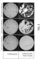
- FIG. 5 show plating integrity progress under a sulphur test.
- the samples shown were tested under the conditions of ASTM B799-95 for consecutive 4 and 9 hours.
- the results show disintegration of the Ni/Au and Ni/Pd plating while the disclosed coating (Au/Pd) remains highly intact.
- FIG. 6 shows a method 600 of manufacturing a hearing aid including an electric charge contact according to the disclosure.
- the method 600 includes forming 602 a metallic component configured to provide electrical conduction.
- the method 600 includes applying 604 a first layer at least partially located on the metallic component, wherein the first layer comprises gold.
- the method 600 includes applying 606 a second layer at least partially located on the gold layer, wherein the second layer comprises palladium.
- forming 602 a metallic component can include attaching a metallic component.
- Forming 602 can include soldering a metallic component.
- Applying 604 the first layer can include plating. Applying 604 the first layer can include electro-plating.
- Applying 607 the second layer can include plating. Applying 606 the second layer can include electro-plating.
- FIG. 7 shows an example hearing aid according to the disclosure.
- the hearing aid 700 includes a hearing aid housing 714.
- the hearing aid 700 is configured to be worn behind the user's ears and comprises a behind-the-ear (BTE) part 702 and an in-the-ear part 704.
- BTE behind-the-ear
- the behind-the-ear part 702 is connected to the in-the-ear part 704 via connecting member 706.
- the hearing aid 700 may be configured in other ways e.g., as completely-in-the-ear hearing aids.
- the BTE part 702 comprises an input unit 710 including input transducers (e.g. microphones) for providing an electric input audio signal representative of an input sound.
- the input unit further comprises a wireless receiver 712 (or transceivers) for providing directly received auxiliary audio and/or control input signals (and/or allowing transmission of audio and/or control signals to other devices, e.g. to another hearing device, or to a remote control or processing device, or a telephone).
- the hearing aid 700 includes a number of electronic components, such a memory 714, e.g. storing different hearing aid programs (e.g. parameter settings defining such programs, or parameters of algorithms) and/or hearing aid configurations, e.g. input source combinations, e.g. optimized for a number of different listening situations.
- different hearing aid programs e.g. parameter settings defining such programs, or parameters of algorithms
- hearing aid configurations e.g. input source combinations, e.g. optimized for a number of different listening situations.
- the hearing aid 700 further comprises a processing unit 716, such as configurable signal processor (DSP, e.g. a digital (audio) signal processor), e.g. including a processor for applying a frequency and level dependent gain, e.g. providing hearing loss compensation, beamforming, noise reduction, filter bank functionality, and other digital functionality of a hearing device.
- DSP configurable signal processor
- the processing unit 716 is adapted to access the memory 714.
- the processing unit 716 is further configured to process one or more of the electric input audio signals and/or one or more of the directly received auxiliary audio input signals, based on a currently selected (activated) hearing aid program/parameter setting (e.g. either automatically selected, e.g. based on one or more sensors, or selected based on inputs from a user interface).
- the hearing aid 700 further comprises an output unit 718 (e.g. an output transducer) providing stimuli perceivable by the user as sound based on a processed audio signal from the processor or a signal derived therefrom.
- an output unit 718 e.g. an output transducer
- the hearing aid 700 can further include a battery unit 720, such as for providing electrical power to one or more components of the hearing aid 700.
- One or more of the components 710, 712, 714, 716, 718, 720 and/or other components can include the electric charge contact disclosed herein.
Landscapes
- Engineering & Computer Science (AREA)
- Signal Processing (AREA)
- General Health & Medical Sciences (AREA)
- Neurosurgery (AREA)
- Otolaryngology (AREA)
- Physics & Mathematics (AREA)
- Health & Medical Sciences (AREA)
- Acoustics & Sound (AREA)
- Chemical & Material Sciences (AREA)
- Manufacturing & Machinery (AREA)
- Chemical Kinetics & Catalysis (AREA)
- Electrochemistry (AREA)
- Materials Engineering (AREA)
- Metallurgy (AREA)
- Organic Chemistry (AREA)
- Electroplating Methods And Accessories (AREA)
- Charge And Discharge Circuits For Batteries Or The Like (AREA)
Applications Claiming Priority (1)
| Application Number | Priority Date | Filing Date | Title |
|---|---|---|---|
| EP23200471 | 2023-09-28 |
Publications (1)
| Publication Number | Publication Date |
|---|---|
| EP4531434A1 true EP4531434A1 (fr) | 2025-04-02 |
Family
ID=88236531
Family Applications (1)
| Application Number | Title | Priority Date | Filing Date |
|---|---|---|---|
| EP24201526.1A Pending EP4531434A1 (fr) | 2023-09-28 | 2024-09-20 | Prothèse auditive ayant des contacts de charge électrique améliorés |
Country Status (3)
| Country | Link |
|---|---|
| US (1) | US20250113150A1 (fr) |
| EP (1) | EP4531434A1 (fr) |
| CN (1) | CN119729324A (fr) |
Citations (5)
| Publication number | Priority date | Publication date | Assignee | Title |
|---|---|---|---|---|
| EP0168018A1 (fr) * | 1984-07-09 | 1986-01-15 | The Furukawa Electric Co., Ltd. | Procédé de placage métallique d'acier inoxydable |
| WO2016025419A1 (fr) * | 2014-08-14 | 2016-02-18 | Microsoft Technology Licensing, Llc | Dispositif électronique à contact électrique plaqué |
| EP4096239A1 (fr) * | 2015-09-30 | 2022-11-30 | Apple Inc. | Boîtier d'écouteur avec insert pour un capteur capacitif |
| US20230002859A1 (en) * | 2021-07-02 | 2023-01-05 | Xtalic Corporation | Nanocrystalline platinum alloy layers and related articles |
| EP4187925A1 (fr) * | 2021-11-29 | 2023-05-31 | Sonova AG | Dispositif auditif |
-
2024
- 2024-09-18 US US18/888,220 patent/US20250113150A1/en active Pending
- 2024-09-20 EP EP24201526.1A patent/EP4531434A1/fr active Pending
- 2024-09-29 CN CN202411369710.1A patent/CN119729324A/zh active Pending
Patent Citations (5)
| Publication number | Priority date | Publication date | Assignee | Title |
|---|---|---|---|---|
| EP0168018A1 (fr) * | 1984-07-09 | 1986-01-15 | The Furukawa Electric Co., Ltd. | Procédé de placage métallique d'acier inoxydable |
| WO2016025419A1 (fr) * | 2014-08-14 | 2016-02-18 | Microsoft Technology Licensing, Llc | Dispositif électronique à contact électrique plaqué |
| EP4096239A1 (fr) * | 2015-09-30 | 2022-11-30 | Apple Inc. | Boîtier d'écouteur avec insert pour un capteur capacitif |
| US20230002859A1 (en) * | 2021-07-02 | 2023-01-05 | Xtalic Corporation | Nanocrystalline platinum alloy layers and related articles |
| EP4187925A1 (fr) * | 2021-11-29 | 2023-05-31 | Sonova AG | Dispositif auditif |
Also Published As
| Publication number | Publication date |
|---|---|
| CN119729324A (zh) | 2025-03-28 |
| US20250113150A1 (en) | 2025-04-03 |
Similar Documents
| Publication | Publication Date | Title |
|---|---|---|
| EP1414520B1 (fr) | Microphone auxiliaire intraconduit pour prothese auditive | |
| US12284490B2 (en) | Speaker unit for a hearing aid device system, and hearing aid device system | |
| CN111669691A (zh) | 包括传感器配置检测器的听力装置 | |
| EP3343953A1 (fr) | Dispositif auditif avec une antenne externe ainsi qu'un élément interne parasite | |
| EP3998779A2 (fr) | Procédé et système d'aide auditive binaurale et aide auditive comprenant une estimation de la propre voix d'un utilisateur | |
| EP2348141B1 (fr) | Utilisation d'anode sacrificielle pour la protection contre la corrosion d'un dispositif portable, par exemple un dispositif d'aide auditive | |
| EP4047957B1 (fr) | Dispositif auditif comprenant un module de batterie et procédé de fabrication d'un module de batterie pour un dispositif auditif | |
| US8750548B2 (en) | Listening device adapted for establishing an electric connection to an external device using electrically conductive parts of one or more components of the listening device | |
| EP2178314B1 (fr) | Dispositif auditif doté d'une membrane sur l'espace intérieur du compartiment de batterie | |
| EP4531434A1 (fr) | Prothèse auditive ayant des contacts de charge électrique améliorés | |
| CN116806006A (zh) | 包括连接件的助听装置 | |
| EP4429270A1 (fr) | Instrument auditif avec protection contre la corrosion améliorée | |
| US20250254457A1 (en) | Charger device for hearing devices | |
| US20230197094A1 (en) | Electronic device and method for obtaining a user's speech in a first sound signal | |
| EP4362499A1 (fr) | Prothèse auditive avec suspension améliorée | |
| CN220253471U (zh) | 听力设备的天线 | |
| EP3972290A1 (fr) | Système de contact de batterie dans un appareil auditif | |
| DE102019204500A1 (de) | Hörgerät |
Legal Events
| Date | Code | Title | Description |
|---|---|---|---|
| PUAI | Public reference made under article 153(3) epc to a published international application that has entered the european phase |
Free format text: ORIGINAL CODE: 0009012 |
|
| STAA | Information on the status of an ep patent application or granted ep patent |
Free format text: STATUS: THE APPLICATION HAS BEEN PUBLISHED |
|
| AK | Designated contracting states |
Kind code of ref document: A1 Designated state(s): AL AT BE BG CH CY CZ DE DK EE ES FI FR GB GR HR HU IE IS IT LI LT LU LV MC ME MK MT NL NO PL PT RO RS SE SI SK SM TR |
|
| STAA | Information on the status of an ep patent application or granted ep patent |
Free format text: STATUS: REQUEST FOR EXAMINATION WAS MADE |
|
| 17P | Request for examination filed |
Effective date: 20251002 |