EP4531452A1 - Dispositif électronique permettant de fournir un service audio, et son procédé de fonctionnement - Google Patents
Dispositif électronique permettant de fournir un service audio, et son procédé de fonctionnement Download PDFInfo
- Publication number
- EP4531452A1 EP4531452A1 EP23824092.3A EP23824092A EP4531452A1 EP 4531452 A1 EP4531452 A1 EP 4531452A1 EP 23824092 A EP23824092 A EP 23824092A EP 4531452 A1 EP4531452 A1 EP 4531452A1
- Authority
- EP
- European Patent Office
- Prior art keywords
- electronic device
- packet
- communication link
- quality
- packets
- Prior art date
- Legal status (The legal status is an assumption and is not a legal conclusion. Google has not performed a legal analysis and makes no representation as to the accuracy of the status listed.)
- Pending
Links
Images


Classifications
-
- H—ELECTRICITY
- H04—ELECTRIC COMMUNICATION TECHNIQUE
- H04W—WIRELESS COMMUNICATION NETWORKS
- H04W72/00—Local resource management
- H04W72/50—Allocation or scheduling criteria for wireless resources
- H04W72/54—Allocation or scheduling criteria for wireless resources based on quality criteria
-
- H—ELECTRICITY
- H04—ELECTRIC COMMUNICATION TECHNIQUE
- H04L—TRANSMISSION OF DIGITAL INFORMATION, e.g. TELEGRAPHIC COMMUNICATION
- H04L47/00—Traffic control in data switching networks
- H04L47/10—Flow control; Congestion control
- H04L47/32—Flow control; Congestion control by discarding or delaying data units, e.g. packets or frames
-
- H—ELECTRICITY
- H04—ELECTRIC COMMUNICATION TECHNIQUE
- H04L—TRANSMISSION OF DIGITAL INFORMATION, e.g. TELEGRAPHIC COMMUNICATION
- H04L47/00—Traffic control in data switching networks
- H04L47/10—Flow control; Congestion control
- H04L47/28—Flow control; Congestion control in relation to timing considerations
-
- H—ELECTRICITY
- H04—ELECTRIC COMMUNICATION TECHNIQUE
- H04L—TRANSMISSION OF DIGITAL INFORMATION, e.g. TELEGRAPHIC COMMUNICATION
- H04L65/00—Network arrangements, protocols or services for supporting real-time applications in data packet communication
- H04L65/60—Network streaming of media packets
- H04L65/75—Media network packet handling
- H04L65/752—Media network packet handling adapting media to network capabilities
-
- H—ELECTRICITY
- H04—ELECTRIC COMMUNICATION TECHNIQUE
- H04L—TRANSMISSION OF DIGITAL INFORMATION, e.g. TELEGRAPHIC COMMUNICATION
- H04L47/00—Traffic control in data switching networks
- H04L47/10—Flow control; Congestion control
- H04L47/24—Traffic characterised by specific attributes, e.g. priority or QoS
- H04L47/2416—Real-time traffic
-
- H—ELECTRICITY
- H04—ELECTRIC COMMUNICATION TECHNIQUE
- H04L—TRANSMISSION OF DIGITAL INFORMATION, e.g. TELEGRAPHIC COMMUNICATION
- H04L65/00—Network arrangements, protocols or services for supporting real-time applications in data packet communication
- H04L65/60—Network streaming of media packets
- H04L65/75—Media network packet handling
- H04L65/762—Media network packet handling at the source
-
- H—ELECTRICITY
- H04—ELECTRIC COMMUNICATION TECHNIQUE
- H04L—TRANSMISSION OF DIGITAL INFORMATION, e.g. TELEGRAPHIC COMMUNICATION
- H04L65/00—Network arrangements, protocols or services for supporting real-time applications in data packet communication
- H04L65/80—Responding to QoS
-
- H—ELECTRICITY
- H04—ELECTRIC COMMUNICATION TECHNIQUE
- H04W—WIRELESS COMMUNICATION NETWORKS
- H04W84/00—Network topologies
- H04W84/18—Self-organising networks, e.g. ad-hoc networks or sensor networks
-
- H—ELECTRICITY
- H04—ELECTRIC COMMUNICATION TECHNIQUE
- H04W—WIRELESS COMMUNICATION NETWORKS
- H04W88/00—Devices specially adapted for wireless communication networks, e.g. terminals, base stations or access point devices
- H04W88/02—Terminal devices
Definitions
- the disclosure relates to an electronic device providing an audio service and an operating method thereof.
- a Bluetooth scheme which is one of short-range communication schemes has been actively used, and electronic devices using the Bluetooth scheme have been also widely used.
- a pair of ear buds which may be respectively worn on both ears of a user have been widely used as an ear-wearable device.
- the ear-wearable device may provide various functions. For example, the ear-wearable device may use a microphone to input and identify a user's voice, transmit audio data related to the user's voice to an electronic device (e.g., a smart phone), and use a speaker to output audio data received from the electronic device.
- an electronic device e.g., a smart phone
- the Bluetooth scheme may include a Bluetooth legacy (or Bluetooth classic) scheme and/or a Bluetooth low energy (BLE) scheme.
- Each of electronic devices e.g., a first electronic device (e.g., a left earbud) and a second electronic device (e.g., a right earbud)) providing a low energy audio (LE Audio) service based on a BLE scheme may independently establish a communication link (e.g., a connected isochronous stream (CIS) connection) with an external electronic device (e.g., a smartphone) and transmit and receive data with the external electronic device via the established communication link.
- a communication link e.g., a connected isochronous stream (CIS) connection
- CIS connected isochronous stream
- each of the first electronic device and the second electronic device may operate as an audio sink device, and the external electronic device may operate as an audio source device.
- the first electronic device may perform a role of a first audio channel (e.g., a left audio channel), and the second electronic device may perform a role of a second audio channel (e.g., a right audio channel).
- Each of the first electronic device and the second electronic device may transmit, to the external electronic device, a device capability identifier (ID) (e.g., a CIS ID) related to an audio channel role performed by each of the first electronic device and the second electronic device, at a set time point.
- ID device capability identifier
- the set time point may be a time point at which each of the first electronic device and the second electronic device is connected to the external electronic device, or a time point at which a service (e.g., an audio service) is started.
- the external electronic device may identify the audio channel role performed by each of the first electronic device and the second electronic device based on the device capability ID received from each of the first electronic device and the second electronic device, and may transmit and receive audio data with each of the first electronic device and the second electronic device based on the identified audio channel role.
- the RF environment may affect quality of each of a first communication link (e.g., a CIS connection) between the external electronic device which is an audio source device and the first electronic device which is an audio sink device, a second communication link which is a communication link between the external electronic device and the second electronic device which is another audio sink device, or a third communication link which is a communication link between the first electronic device and the second electronic device.
- a first communication link e.g., a CIS connection
- the first electronic device, the second electronic device, and the external electronic device may stably provide a high-quality audio service even though quality of any one of communication links among the first electronic device, the second electronic device, or the external electronic device becomes lower than the threshold quality.
- An embodiment of the disclosure may provide an electronic device which provides an audio service and an operating method thereof.
- An embodiment of the disclosure may provide an electronic device for performing a packet drop operation on a communication link whose quality is less than threshold quality if the quality of at least one communication link among communication links between electronic devices providing an audio service is less than the threshold quality, and an operating method thereof.
- An embodiment of the disclosure may provide an electronic device for performing a flush point-adjustment operation on a communication link whose quality is less than threshold quality if the quality of at least one communication link among communication links between electronic devices providing an audio service is less than the threshold quality, and an operating method thereof.
- An electronic device may include a communication circuit and at least one processor operably connected to the communication circuit.
- the at least one processor may be configured to establish, via the communication circuit, a communication link with at least one external electronic device.
- the at least one processor may be further configured to identify quality of the communication link.
- the at least one processor may be further configured to, based on the quality of the communication link being less than threshold quality, discard at least one of packets to be transmitted during a set time period on the communication link.
- the at least one processor may be further configured to transmit, to the at least one external electronic device, via the communication circuit, a packet indicating that the at least one packet is discarded.
- An electronic device may include a communication circuit and at least one processor operably connected to the communication circuit.
- the at least one processor may be further configured to establish, via the communication circuit, a communication link with an external electronic device.
- the at least one processor may be further configured to, receive, from the external electronic device via the communication circuit, at least one packet during a set time period via the communication link.
- the at least one processor may be further configured to identify whether a packet indicating that the packet is discarded is included in the received at least one packet.
- the at least one processor may be further configured to, based on the packet indicating that the packet is discarded being included in the received at least one packet, perform a recovery operation on a packet corresponding to the packet indicating that the packet is discarded.
- An operating method of an electronic device may include establishing a communication link with at least one external electronic device.
- the operating method may further include identifying quality of the communication link.
- the operating method may further include, based on the quality of the communication link being less than threshold quality, discarding at least one of packets to be transmitted during a set time period on the communication link.
- the operating method may further include, transmitting, to the at least one external electronic device, a packet indicating that the at least one packet is discarded.
- An operating method of an electronic device may include establishing a communication link with an external electronic device.
- the operating method may further include receiving, from the external electronic device, at least one packet during a set time period via the communication link.
- the operating method may further include identifying whether a packet indicating that the packet is discarded is included in the received at least one packet.
- the operating method may further include, based on the packet indicating that the packet is discarded being included in the received at least one packet, performing a recovery operation on a packet corresponding to the packet indicating that the packet is discarded.
- a non-transitory computer-readable storage medium may include one or more programs including instructions, when executed by at least one processor of an electronic device, configured to cause the electronic device to establish a communication link with at least one external electronic device.
- the instructions may be further configured to cause the electronic device to identify quality of the communication link.
- the instructions may be further configured to cause the electronic device to, based on the quality of the communication link being less than threshold quality, discard at least one of packets to be transmitted during a set time period on the communication link.
- a non-transitory computer-readable storage medium may include one or more programs including instructions, when executed by at least one processor of an electronic device, configured to cause the electronic device to establish a communication link with an external electronic device.
- the instructions may be further configured to cause the electronic device to receive, from the external electronic device, at least one packet during a set time period in the communication link.
- the display module 160 may visually provide information to the outside (e.g., a user) of the electronic device 101.
- the display module 160 may include, for example, a display, a hologram device, or a projector and control circuitry to control a corresponding one of the display, hologram device, and projector.
- the display module 160 may include a touch sensor adapted to detect a touch, or a pressure sensor adapted to measure the intensity of force incurred by the touch.
- each of the first electronic device 202 and the second electronic device 204 may operate as an audio sink device, and the external electronic device 201 may operate as an audio source device.
- the first electronic device 202 may perform a first audio channel (e.g., left audio channel) role
- the second electronic device 204 may perform a second audio channel (e.g., right audio channel) role.
- the external electronic device 201 and the first electronic device 202 and the second electronic device 204 may establish a connection (e.g., a communication link) with one another and transmit and/or receive data (e.g., audio data) to and from one another.
- the electronic device 101 and each of the first electronic device 202 and the second electronic device 204 may establish a communication link based on at least one of a Wi-Fi scheme or a Bluetooth scheme, however, a scheme for establishing the communication link in the electronic device 101 and each of the first electronic device 202 and the second electronic device 204 is not limited to at least one of the Wi-Fi scheme and/or the Bluetooth scheme.
- the communication link may be a connected isochronous stream (CIS) connection.
- CIS isochronous stream
- the first electronic device 202 and the second electronic device 204 may establish a communication link based on at least one of the Wi-Fi scheme or the Bluetooth scheme, however, a scheme for establishing the communication link in the first electronic device 202 and the second electronic device 204 is not limited to at least one of the Wi-Fi scheme or the Bluetooth scheme.
- the communication link may be the CIS connection.
- the communication link established between the first electronic device 202 and the second electronic device 204 may be the second communication link.
- one of the first electronic device 202 and the second electronic device 204 may be a central device (or a master device, a primary device, or a main device), and the other one may operate as a peripheral device (or a slave device, a secondary device, or a sub device).
- An electronic device operating as a central device may transmit data to an electronic device operating as a peripheral device.
- one of the first electronic device 202 and the second electronic device 204 may be selected as a central device, and the other one may be selected as a peripheral device.
- the first electronic device 202 and/or the second electronic device 204 may communicate directly or indirectly with a third electronic device 300.
- the third electronic device 300 may be an ear buds case device or a cradle device which stores and charges the first electronic device 202 and/or the second electronic device 204, and for convenience of description, it will be assumed that the third electronic device 300 is the ear buds case device.
- an external electronic device 201 may be a device implementing a Bluetooth scheme (e.g., a Bluetooth low energy (BLE) scheme).
- the external electronic device 201 may include a communication circuit 302 (e.g., a communication module 190) which transmits and receives signals with another electronic device (e.g., an electronic device 102 or an electronic device 104 in FIG. 1 ), for example, a peer device by using one or more antennas 301.
- the other electronic device may include at least one of a first electronic device 202 or a second electronic device 204.
- the external electronic device 201 may include a processor 304 (e.g., a processor 120 in FIG. 1 ) which may be implemented in one or more single-core processors or one or more multi-core processors, and a memory 306 (e.g., a memory 130 in FIG. 1 ) which stores instructions for an operation of the external electronic device 201.
- a processor 304 e.g., a processor 120 in FIG. 1
- a memory 306 e.g., a memory 130 in FIG. 1
- the external electronic device 201 may include a plurality of communication circuits, one of the plurality of communication circuits may be a communication circuit which is based on a Wi-Fi scheme, and another of the plurality of communication circuits may be a communication circuit which is based on a Bluetooth scheme, e.g., a BLE scheme.
- the plurality of communication circuits may include a communication circuit 302, and the communication circuit 302 may be a communication circuit which is based on the Wi-Fi scheme or a communication circuit which is based on the BLE scheme.
- an external electronic device 201 may be connected wirelessly to a ear wearable device (e.g., an electronic device 102 in FIG. 1 ).
- the external electronic device 201 may be a smart phone, and the wearable device may include at least one of a first electronic device 202 (e.g., a left earbud) or a second electronic device 204 (e.g., a right earbud).
- the external electronic device 201 may connect a communication link to only one (e.g., a central earbud) of the first electronic device 202 and the second electronic device 204 or may connect communication links with both the first electronic device 202 and the second electronic device 204.
- a communication link to only one (e.g., a central earbud) of the first electronic device 202 and the second electronic device 204 or may connect communication links with both the first electronic device 202 and the second electronic device 204.
- the first electronic device 202 and the second electronic device 204 may establish a communication link based on at least one of the Wi-Fi scheme or the Bluetooth scheme, however, a scheme for establishing the communication link in the first electronic device 202 and the second electronic device 204 is not limited to at least one of the Wi-Fi scheme or the Bluetooth scheme.
- the first electronic device 202 may include the same or similar components to at least one of the components (e.g., modules) of the external electronic device (e.g., an electronic device 101 in FIG. 1 ).
- the first electronic device 202 may include a communication circuit 420 (e.g., a communication module 190 in FIG. 1 ), an input device 430 (e.g., an input module 150 in FIG. 1 ), a sensor 440 (e.g., a sensor module 176 in FIG. 1 ), an audio processing module 450 (e.g., an audio module 170 in FIG. 1 ), a memory 490 (e.g., a memory 130 in FIG.
- a communication circuit 420 e.g., a communication module 190 in FIG. 1
- an input device 430 e.g., an input module 150 in FIG. 1
- a sensor 440 e.g., a sensor module 176 in FIG. 1
- an audio processing module 450 e.g., an audio module 1
- a power management module 460 e.g., a power management module 188 in FIG. 1
- a battery 470 e.g., a battery 189 in FIG. 1
- an interface 480 e.g., an interface 177 in FIG. 1
- a processor 410 e.g., a processor 120 in FIG. 1
- the communication circuit 420 may include at least one of a wireless communication module (e.g., a Bluetooth communication module, a cellular communication module, a wireless-fidelity (Wi-Fi) communication module, a near-field communication (NFC) communication module, or a GNSS communication module) or a wired communication module (e.g., a LAN communication module or a power line communication (PLC) communication module).
- a wireless communication module e.g., a Bluetooth communication module, a cellular communication module, a wireless-fidelity (Wi-Fi) communication module, a near-field communication (NFC) communication module, or a GNSS communication module
- a wired communication module e.g., a LAN communication module or a power line communication (PLC) communication module.
- PLC power line communication
- the communication circuit 420 may directly or indirectly communicate with at least one of the external electronic device 201, the third electronic device 300, or the second electronic device 204 through a first network (e.g., a first network 198 in FIG. 1 ), using at least one communication module.
- the second electronic device 204 may compose a pair with the first electronic device 202.
- the communication module 420 may include one or more communication processors which are operable independently from the processor 410 and supports wired or wireless communication.
- the communication circuit 420 may be connected to one or a plurality of antennas for transmitting signals or information to another electronic device (e.g., the external electronic device 201, the second electronic device 204, or the third electronic device 300) or receiving signals or information from the other electronic device.
- at least one antenna appropriate for a communication scheme used in a communication network such as the first network (e.g., the first network 198 of FIG. 1 ) or the second network (e.g., the second network 199 of FIG. 2 ), may be selected from the plurality of antennas by the communication circuit 420.
- the signal or information may then be transmitted or received between the communication circuit 420 and another electronic device via the selected at least one antenna.
- the input device 430 may be configured to generate various input signals that may be used for operation of the first electronic device 202.
- the input device 430 may include at least one of a touch pad, a touch panel, or a button.
- the input device 430 may generate a user input related to the turn-on or turn-off of the first electronic device 202. According to an embodiment, the input device 430 may receive a user input for establishing a communication link between the first electronic device 202 and the second electronic device 204. According to an embodiment, the input device 430 may receive a user input related to audio data (or audio content). For example, the user input may be associated with functions of starting playback of audio data, pausing playback, stopping playback, adjusting playback speed, adjusting playback volume, or muting.
- the sensor 440 may obtain a location or an operation state of the first electronic device 202.
- the sensor 440 may convert an obtained signal into an electric signal.
- the sensor 440 may include at least one of a magnetic sensor, an acceleration sensor, a gyro sensor, a geomagnetic sensor, a proximity sensor, a gesture sensor, a grip sensor, a biometric sensor, and/or an optical sensor.
- the processor 410 may obtain data (e.g., audio data) from a packet (e.g., an audio packet) received from the external electronic device 201, and process the obtained data via the audio processing module 450 to output the processed data to the speaker 454.
- the audio processing module 450 may support an audio data gathering function and reproduce the gathered audio data.
- the audio processing module 450 may include an audio decoder (not shown) and a D/A converter (not shown).
- the audio decoder may convert audio data stored in the memory 490 or received from the external electronic device 201 via communication circuit 420 into a digital audio signal.
- the D/A converter may convert the digital audio signal converted by the audio decoder into an analog audio signal.
- the audio decoder may convert audio data received from the external electronic device 201 via the communication circuit 420 and stored in the memory 490 into a digital audio signal.
- the speaker 454 may output the analog audio signal converted by the D/A converter.
- the audio processing module 450 may include an A/D converter (not shown).
- the A/D converter may convert the analog audio signal transferred via a microphone 452 into a digital voice signal.
- the microphone 452 may include at least one air conduction microphone and/or at least one bone conduction microphone for obtaining voice and/or sound.
- the audio processing module 450 may play various audio data set in the operation of the first electronic device 202.
- the processor 410 may be designed to identify insertion or removal of the first electronic device 202 into/from the user's ear via the sensor 440 and reproduce audio data regarding an effect sound or guide sound via the audio processing module 450.
- the output of the sound effect or guide sound may be omitted according to the user setting or the designer's intention.
- the memory 490 may store various data used by at least one component (e.g., the processor 410 or the sensor 440) of the first electronic device 402.
- data may include software and input data or output data for an instruction related thereto.
- the memory 490 may include a volatile memory or a non-volatile memory.
- the power management module 460 may manage power supplied to the first electronic device 402.
- the power management module 460 may be implemented as at least part of a power management integrated circuit (PMIC).
- the power management module 460 may include a battery charging module.
- the power management module 460 may receive power from the other electronic device to charge the battery 470.
- the battery 470 may supply power to at least one component of the first electronic device 202.
- the battery 470 may include a rechargeable battery.
- the first electronic device 202 may charge the battery 470 to a designated charge level and then power on the first electronic device 202 or turn on at least part of the communication circuit 420.
- the interface 480 may support one or more designated protocols which may be used for the first electronic device 402 to directly (e.g., wiredly) connect to the external electronic device 201, the third electronic device 300, the second electronic device 204, or another electronic device.
- the interface 480 may include at least one of a high definition multimedia interface (HDMI), a USB interface, an SD card interface, a power line communication (PLC) interface, or an audio interface.
- the interface 480 may include at least one connection port for establishing a physical connection with the third electronic device 300.
- the processor 410 may execute software to control at least one other component (e.g., a hardware or software component) of the first electronic device 202 connected with the processor 410 and may process or compute various data.
- the processor 410 may load an instruction or data received from another component (e.g., the sensor 440 or communication circuit 420) onto a volatile memory 490, process the instruction or the data stored in the volatile memory 490, and store resulting data in a non-volatile memory.
- the processor 410 may establish a communication link with the external electronic device 201 via the communication circuit 420 and receive data (e.g., audio data) from the external electronic device 201 through the established communication link. According to an embodiment, the processor 410 may transmit the data, received from the electronic device 101 via the communication circuit 420, to the second electronic device 204. According to an embodiment, the processor 410 may perform operations of the first electronic device 202 which are to be described below.
- the first electronic device 202 may further include various modules depending on the form in which it is provided. There are many variations according to the convergence trend of digital devices, so it is not possible to list them all, but components equivalent to the above-mentioned components may be further included in the first electronic device 202. Further, it is apparent that in the first electronic device 202 according to an embodiment, specific components may be excluded from the components described in FIG. 4 or the specific components may be replaced with other components according to the form in which it is provided.
- the second electronic device 204 configured in pair with the first electronic device 202 may include the same or substantially similar components to those included in the first electronic device 202 and may perform all or some of operations of the first electronic device 202 to be described below.
- an electronic device may include a communication circuit (e.g., a communication module 190 in FIG. 1 or a communication circuit 302 in FIG. 3 ), and at least one processor (e.g., a processor 120 in FIG. 1 or a processor 304 in FIG. 3 ) operably connected with the communication circuit (e.g., the communication module 190 in FIG. 1 or the communication circuit 302 in FIG. 3 ).
- a communication circuit e.g., a communication module 190 in FIG. 1 or a communication circuit 302 in FIG. 3
- at least one processor e.g., a processor 120 in FIG. 1 or a processor 304 in FIG. 3
- the communication circuit e.g., the communication module 190 in FIG. 1 or the communication circuit 302 in FIG. 3
- the at least one processor may be configured to establish, via the communication circuit (e.g., the communication module 190 in FIG. 1 or the communication circuit 302 in FIG. 3 ), a communication link with at least one external electronic device (e.g., a first electronic device 202 in FIG. 2 or FIG. 4 , or a second electronic device 204 in FIG. 2 or FIG. 4 ).
- the communication circuit e.g., the communication module 190 in FIG. 1 or the communication circuit 302 in FIG. 3
- at least one external electronic device e.g., a first electronic device 202 in FIG. 2 or FIG. 4 , or a second electronic device 204 in FIG. 2 or FIG. 4 .
- the at least one processor may be further configured to identify quality of the communication link.
- the at least one processor may be further configured to, based on the quality of the communication link being less than threshold quality, discard at least one of packets to be transmitted during a set time period on the communication link.
- the at least one processor may be further configured to transmit, to the at least one external electronic device (e.g., the first electronic device 202 in FIG. 2 or FIG. 4 , or the second electronic device 204 in FIG. 2 or FIG. 4 ), via the communication circuit (e.g., the communication module 190 in FIG. 1 or the communication circuit 302 in FIG. 3 ), a packet indicating that the at least one packet is discarded.
- the at least one external electronic device e.g., the first electronic device 202 in FIG. 2 or FIG. 4 , or the second electronic device 204 in FIG. 2 or FIG. 4
- the communication circuit e.g., the communication module 190 in FIG. 1 or the communication circuit 302 in FIG. 3
- the at least one processor may be further configured to, based on the quality of the communication link being less than the threshold quality, adjust flush points which are time points at which the packets to be transmitted during the set time period are set to be discarded.
- the at least one processor may be configured to discard the at least one packet at a time point preceding a flush point, which is a time point at which the at least one packet is set to be discarded, in a time domain.
- the at least one processor may be configured to transmit, to the at least one external electronic device (e.g., the first electronic device 202 in FIG. 2 or FIG. 4 , or the second electronic device 204 in FIG. 2 or FIG. 4 ), via the communication circuit (e.g., the communication module 190 in FIG. 1 or the communication circuit 302 in FIG. 3 ), packets during another set time period preceding the set time period in a time domain.
- the at least one external electronic device e.g., the first electronic device 202 in FIG. 2 or FIG. 4 , or the second electronic device 204 in FIG. 2 or FIG. 4
- the communication circuit e.g., the communication module 190 in FIG. 1 or the communication circuit 302 in FIG. 3
- the at least one processor may be configured to receive, from the at least one external electronic device (e.g., the first electronic device 202 in FIG. 2 or FIG. 4 , or the second electronic device 204 in FIG. 2 or FIG. 4 ), via the communication circuit (e.g., the communication module 190 in FIG. 1 or the communication circuit 302 in FIG. 3 ), during the other set time period, at least one response packet for the packets transmitted during the other set time period.
- the at least one external electronic device e.g., the first electronic device 202 in FIG. 2 or FIG. 4 , or the second electronic device 204 in FIG. 2 or FIG. 4
- the communication circuit e.g., the communication module 190 in FIG. 1 or the communication circuit 302 in FIG. 3
- the at least one processor may be configured to, based on the at least one response packet, identify the quality of the communication link.
- the at least one processor may be configured to, based on a maximum number of sub-events included in each connected isochronous stream (CIS) event included in the set time period and a number of new data packets which may be transmitted within a time interval in which a CIS event occurs, adjust the flush points for the packets to be transmitted during the set time period.
- CIS isochronous stream
- each CIS event may include an opportunity for the electronic device (e.g., the electronic device 101 in FIG. 1 , or the external electronic device 201 in FIG. 2, FIG. 3 , or FIG. 4 ) and the at least one external electronic device (e.g., the first electronic device 202 in FIG. 2 or FIG. 4 , or the second electronic device 204 in FIG. 2 or FIG. 4 ) to exchange a packet.
- the electronic device e.g., the electronic device 101 in FIG. 1 , or the external electronic device 201 in FIG. 2, FIG. 3 , or FIG. 4
- the at least one external electronic device e.g., the first electronic device 202 in FIG. 2 or FIG. 4 , or the second electronic device 204 in FIG. 2 or FIG. 4
- each of the sub-events may be used for the electronic device (e.g., the electronic device 101 in FIG. 1 , or the external electronic device 201 in FIG. 2, FIG. 3 , or FIG. 4 ) to transmit a packet and for the at least one external electronic device (e.g., the first electronic device 202 in FIG. 2 or FIG. 4 , or the second electronic device 204 in FIG. 2 or FIG. 4 ) to respond to the electronic device (e.g., the electronic device 101 in FIG. 1 , or the external electronic device 201 in FIG. 2, FIG. 3 , or FIG. 4 ).
- the electronic device e.g., the electronic device 101 in FIG. 1 , or the external electronic device 201 in FIG. 2, FIG. 3 , or FIG. 4
- the electronic device e.g., the electronic device 101 in FIG. 1 , or the external electronic device 201 in FIG. 2, FIG. 3 , or FIG. 4
- the electronic device e.g., the electronic device 101 in FIG. 1 , or
- the at least one processor may be configured to, based on a set discard ratio, discard at least one of the packets to be transmitted during the set time period.
- the set discard ratio includes a ratio of a number of acknowledgement (ACK) packets continuously received for a set number of packets among the packets to be transmitted during the set time period to a packet indicating that the at least one packet is discarded.
- ACK acknowledgement
- the at least one processor may be further configured to transmit, to the at least one external electronic device (e.g., the first electronic device 202 in FIG. 2 or FIG. 4 , or the second electronic device 204 in FIG. 2 or FIG. 4 ), via the communication circuit (e.g., the communication module 190 in FIG. 1 or the communication circuit 302 in FIG. 3 ), a packet including information associated with the adjusted flush points.
- the at least one external electronic device e.g., the first electronic device 202 in FIG. 2 or FIG. 4 , or the second electronic device 204 in FIG. 2 or FIG. 4
- the communication circuit e.g., the communication module 190 in FIG. 1 or the communication circuit 302 in FIG. 3
- the packet indicating that the at least one packet is discarded may be an empty packet, a null packet, or a special packet.
- an electronic device may include a communication circuit (e.g., a communication circuit 420 in FIG. 4 ), and at least one processor (e.g., a processor 410 in FIG. 4 ) operably connected with the communication circuit (e.g., the communication circuit 420 in FIG. 4 ).
- a communication circuit e.g., a communication circuit 420 in FIG. 4
- at least one processor e.g., a processor 410 in FIG. 4
- the at least one processor may be configured to establish, via the communication circuit (e.g., the communication circuit 420 in FIG. 4 ), a communication link with an external electronic device (e.g., an electronic device 101 in FIG. 1 , or an external electronic device 201 in FIG. 1 , FIG. 2 , or FIG. 4 ).
- the communication circuit e.g., the communication circuit 420 in FIG. 4
- an external electronic device e.g., an electronic device 101 in FIG. 1 , or an external electronic device 201 in FIG. 1 , FIG. 2 , or FIG. 4 .
- the at least one processor may be further configured to receive, from the external electronic device (e.g., the electronic device 101 in FIG. 1 , or the external electronic device 201 in FIG. 1 , FIG. 2 , or FIG. 4 ), via the communication circuit (e.g., the communication circuit 420 in FIG. 4 ), at least one packet during a set time period in the communication link.
- the external electronic device e.g., the electronic device 101 in FIG. 1 , or the external electronic device 201 in FIG. 1 , FIG. 2 , or FIG. 4
- the communication circuit e.g., the communication circuit 420 in FIG. 4
- the at least one processor may be further configured to identify whether a packet indicating that the packet is discarded is included in the received at least one packet.
- the at least one processor may be further configured to, based on the packet indicating that the packet is discarded being included in the received at least one packet, perform a recovery operation on a packet corresponding to the packet indicating that the packet is discarded.
- the at least one packet may be discarded at a time point preceding a flush point, which is a time point at which the at least one packet is set to be discarded, in a time domain.
- the at least one packet may be included in the packets transmitted during the set time period, and the at least one packet may be discarded during the set time period based on a set discard ratio.
- the set discard ratio may include a ratio of a number of acknowledgement (ACK) packets continuously received for a set number of packets among the packets transmitted by the external electronic device (e.g., the electronic device 101 in FIG. 1 , or the external electronic device 201 in FIG. 1 , FIG. 2 , or FIG. 4 ) during the set time period to a packet indicating that the packet is discarded.
- ACK acknowledgement
- flush points for the packets transmitted during the set time period may be adjusted by the external electronic device (e.g., the electronic device 101 in FIG. 1 , or the external electronic device 201 in FIG. 1 , FIG. 2 , or FIG. 4 ).
- the external electronic device e.g., the electronic device 101 in FIG. 1 , or the external electronic device 201 in FIG. 1 , FIG. 2 , or FIG. 4 .
- the flush points may be set time points at which the packets transmitted during the set time period are discarded, and the flush points may be adjusted based on a maximum number of sub-events included in each connected isochronous stream (CIS) event included in the set time period and a number of new data packets which may be transmitted within a time interval in which a CIS event occurs.
- CIS connected isochronous stream
- each CIS event may include an opportunity for the electronic device (e.g., the first electronic device 202 in FIG. 2 or FIG. 4 , or the second electronic device 204 in FIG. 2 or FIG. 4 ) and the external electronic device (e.g., the electronic device 101 in FIG. 1 , or the external electronic device 201 in FIG. 1 , FIG. 2 , or FIG. 4 ) to exchange a packet.
- the electronic device e.g., the first electronic device 202 in FIG. 2 or FIG. 4 , or the second electronic device 204 in FIG. 2 or FIG. 4
- the external electronic device e.g., the electronic device 101 in FIG. 1 , or the external electronic device 201 in FIG. 1 , FIG. 2 , or FIG. 4
- each of the sub-events may be used for the external electronic device (e.g., the electronic device 101 in FIG. 1 , or the external electronic device 201 in FIG. 1 , FIG. 2 , or FIG. 4 ) to transmit a packet and for the electronic device (e.g., the first electronic device 202 in FIG. 2 or FIG. 4 , or the second electronic device 204 in FIG. 2 or FIG. 4 ) to respond to the external electronic device (e.g., the electronic device 101 in FIG. 1 , or the external electronic device 201 in FIG. 1 , FIG. 2 , or FIG. 4 ).
- the external electronic device e.g., the electronic device 101 in FIG. 1 , or the external electronic device 201 in FIG. 1 , FIG. 2 , or FIG. 4
- a Bluetooth scheme may include a Bluetooth legacy (or Bluetooth classic) scheme, or a Bluetooth low energy (BLE) scheme.
- Each of electronic devices e.g., a first electronic device 202 and a second electronic device 204 in FIG. 2 or FIG. 4
- a low energy audio (LE Audio) service of the BLE scheme may independently establish a connection (e.g., a communication link) with an external electronic device (e.g., an electronic device 101 in FIG. 1 or an external electronic device 201 in FIG. 2, FIG. 3 , or FIG. 4 ), and transmit and receive data with the external electronic device via the established connection.
- a connection e.g., a communication link
- an external electronic device e.g., an electronic device 101 in FIG. 1 or an external electronic device 201 in FIG. 2, FIG. 3 , or FIG. 4
- the communication link may be a CIS connection.
- a communication link established between the external electronic device and the first electronic device may be a first communication link
- a communication link established between the external electronic device and the second electronic device may be a second communication link
- a communication link established between the first electronic device and the second electronic device may be a third communication link.
- Each of the first electronic device and the second electronic device may operate as an audio sink device, and the external electronic device may operate as an audio source device.
- the first electronic device may perform a first audio channel (e.g., left audio channel) role
- the second electronic device may perform a second audio channel (e.g., right audio channel) role.
- each of the first electronic device and the second electronic device may transmit, to an external electronic device, audio data inputted via a microphone of each of the first electronic device and the second electronic device.
- Each of the first electronic device and the second electronic device may transmit and receive the audio data with the external electronic device via a communication link established based on the BLE scheme.
- An LE audio service provided in a BLE scheme is a next-generation Bluetooth audio service.
- a Bluetooth legacy scheme a Bluetooth basic rate/enhanced data rate (BR/EDR) scheme is used, and an advanced audio distribution profile (A2DP) or a hands-free profile (HFP) is used, whereas in the LE audio service, a broadcast audio scheme for a multi-stream audio scheme and an audio sharing scheme is used.
- B/EDR Bluetooth basic rate/enhanced data rate
- A2DP advanced audio distribution profile
- HFP hands-free profile
- independent audio streams may be transmitted to one or more electronic devices.
- a connected isochronous group (CIG) or a CIS has been introduced to support the multi-stream audio scheme.
- the CIG may be generated by a central device and may include two or more CISes.
- the CIG may include two or more CISes with the same time interval (e.g., ISO_Interval).
- the CIS is a logical transport which enables connected devices to transfer isochronous data in either direction.
- the CIS is based on a point-to-point scheme and is based on acknowledgment (ACK)-based two-way communication.
- ACK acknowledgment
- An isochronous connection may be used to transfer isochronous data between a central device and a peripheral device using a logical transport called CIS.
- the CIS may include CIS events which occur at regular intervals (e.g., a specified ISO_Interval).
- a CIS event may be an opportunity for the central device and peripheral device to exchange audio packets.
- Each CIS event may include one or more sub-events.
- Each sub-event may be used by the central device to transmit an audio packet and the peripheral device to respond to the master device.
- the central device transmits once and the peripheral device may respond. If the central device and the peripheral device completed transferring scheduled isochronous data in a CIS event, all remaining sub-events in the CIS event will have no radio transmissions, so the CIS event may be closed.
- Each sub-event may use a physical channel which is determined by using a channel selection algorithm.
- the physical channel which is used for a sub-event may be marked as ISO Ch(eventcount, subeventcount).
- the eventcount may represent a count value of a corresponding CIS event
- the subeventcount may represent a count value of a sub-event in the corresponding CIS event.
- a CIG event may include CIS events of CISes included in a CIG.
- Each CIG event starts at an anchor point of the earliest (in terms of transmission order) CIS and ends at the end of the last sub-event of the latest (in terms of transmission order) CIS of the same CIG event.
- Two CIG events on the same CIG may not overlap.
- the last CIS event of a given CIG event may end before the first CIS anchor point of the next CIG event.
- FIG. 5 is a diagram illustrating configuration of CIG events and CIS events in a wireless communication network according to an embodiment.
- one CIG event may include two CIS events (e.g., a CIS1 event n 501 and a CIS2 event n 503).
- the CIS1 event n 501 may be a CIS event corresponding to a CIS1
- the CIS2 event n 503 may be a CIS event corresponding to a CIS2.
- CISes included in a CIG may be arranged sequentially or interleaved by appropriately adjusting values of Sub_Interval and spacing between CIS anchor points, and a case that the CIS1 event n 501 and the CIS2 event n 503 included in the CIG event n 500 are arranged sequentially is illustrated in FIG. 5 .
- the CIG event n 500 illustrated in FIG. 5 may be a CIG event including the CIS1 event n 501 and the CIS2 event n 503 in sequential arrangement.
- CIS events of other CISes may not overlap, so sub-events of a CIS event may also not overlap.
- the CIS1 event n 501 and the CIS2 event n 503 may not overlap, so sub-events included in the CIS1 event n 501 (e.g., a sub-event 1 511, a sub-event 2 512, a sub-event 3 513, a sub-event 4 514) and sub-events included in the CIS2 event n 503 (e.g., a sub-event 1 541, a sub-event 2 542, a sub-event 3 543, and a sub-event 4 544) may not overlap.
- sub-events of a plurality of CIS events may overlap.
- at least one of the sub-events included in the CIS1 event n 501 and at least one of the sub-events included in the CIS2 event n 503 may overlap.
- the central device may transmit a connected isochronous protocol data unit (PDU) 521 in the sub-event 1 511, the central device may transmit a connected isochronous PDU 522 in the sub-event 2 512, the central device may transmit a connected isochronous PDU 523 in the sub-event 3 513, and the central device may transmit a connected isochronous PDU 524 in the sub-event 4 514.
- PDU connected isochronous protocol data unit
- Each of the connected isochronous PDU 521, the connected isochronous PDU 522, the connected isochronous PDU 523, and the connected isochronous PDU 524 may be a connected isochronous PDU transmitted from a central device to a peripheral device.
- the second peripheral device may transmit a connected isochronous PDU 561 in the sub-event 1 541, the second peripheral device may transmit a connected isochronous PDU 562 in the sub-event 2 542, the second peripheral device may transmit a connected isochronous PDU 563 in the sub-event 3 543, and the first peripheral device may transmit a connected isochronous PDU 564 in the sub-event 4 564.
- Each of the connected isochronous PDU 561, the connected isochronous PDU 562, the connected isochronous PDU 563, and the connected isochronous PDU 564 may be a connected isochronous PDU transmitted from the second peripheral device to the central device.
- one or more audio packets may be provided to an infinite number of audio sink devices.
- a broadcast isochronous group (BIG) and a broadcast isochronous stream (BIS) have been proposed.
- BIG broadcast isochronous group
- BIOS broadcast isochronous stream
- an isochronous broadcaster and a synchronized receiver may be required.
- the BIS may be a logical transport used to transfer one or more isochronous data streams to all devices for the BIS within a range.
- the BIS may include one or more sub-events for transmitting isochronous data packets.
- a sub-event may include slots in which an infinite number of synchronized receivers may receive a broadcast isochronous PDU.
- the BIS may support transmission of a plurality of new isochronous data packets in every BIS event. There is no acknowledgment protocol for the BIS, so traffic is unidirectional from a broadcasting device.
- the BIG may be generated by the isochronous broadcaster.
- the BIG may include one or more BISes.
- a plurality of BISes included in the BIG may have a common timing reference based on a broadcaster and may be synchronized in a time domain. For example, a left channel and a right channel of an audio stereo stream, received by separate devices, may need to be rendered simultaneously.
- the plurality of BISes included in the BIG may be scheduled sequentially or in an interleaved arrangement.
- each of BIG events may include two BIS events.
- the BIG event x 601 may include a BIS1 event x 611 and a BIS2 event x 613
- the BIG event x+1 603 may include a BIS1 event x+1 621 and a BIS2 event x+ 1 623
- the BIG event x+2 605 may include a BIS1 event x+2 631 and a BIS2 event x+2 633.
- a BIG event may include one or more BIS PDUs.
- a link layer may transmit BIS PDUs only in BIG events. The link layer may transmit only BIS PDUs as part of the BIG event.
- Each BIG event may be divided into Num_BIS BIS events and a control sub-event (if present).
- Each BIS event may be divided into NSE sub-events.
- Each BIS event starts at a moment called BIS anchor point and ends after the last sub-event of each BIS event.
- Each BIG event starts at a moment called BIG anchor point, and ends after one control sub-event if there is the one control sub-event, and otherwise, at the end of the last constituent BIS event.
- BIS anchor points may be spaced regularly at ISO_Intervals.
- BIS anchor points for a BIS n of a BIG may be (n - 1) Y BIS_Spacing after the BIG anchor points, so may be also spaced regularly, ISO_Interval apart.
- BIS_Spacing may be time between start of sub-events in adjacent BISes included in the BIG and also time between start of the first sub-event of the last BIS and a control sub-event, if present.
- Sub-events of each BIS may be Sub_Interval apart.
- the Isochronous broadcaster may close each BIG event at least T_IFS before a BIG anchor point of the next BIG event.
- a broadcast isochronous PDU 641, a broadcast isochronous PDU 643, and a broadcast isochronous PDU 645 may be transmitted.
- a broadcast isochronous PDU 651, a broadcast isochronous PDU 653, and a broadcast isochronous PDU 655 may be transmitted.
- a broadcast isochronous PDU 661, a broadcast isochronous PDU 663, and a broadcast isochronous PDU 665 may be transmitted.
- a broadcast isochronous PDU 671, a broadcast isochronous PDU 673, and a broadcast isochronous PDU 675 may be transmitted.
- a broadcast isochronous PDU 681, a broadcast isochronous PDU 683, and a broadcast isochronous PDU 685 may be transmitted.
- a broadcast isochronous PDU 691, a broadcast isochronous PDU 693, and a broadcast isochronous PDU 695 may be transmitted.
- a first electronic device, a second electronic device, and an external electronic device are providing an audio service (e.g., an LE Audio service) based on a BLE scheme
- an audio service e.g., an LE Audio service
- normal provision of the audio service may become impossible due to a change in a radio frequency (RF) environment.
- the RF environment may affect quality of each of a first communication link which is a communication link between the first electronic device and the external electronic device, a second communication link which is a communication link between the second electronic device and the external electronic device, and/or a third communication link which is a communication link between the first electronic device and the second electronic device.
- quality of a communication link may be determined based on channel quality.
- the channel quality may be represented by at least one of a moving average value (e.g., an exponential moving average (EMA) value), the number of unacked packets during an evaluation period, the number of flushed packets during the evaluation period, a noise level, a block error rate (BLER), a frame error rate (FER), a bit error rate (BER), a packet error rate (PER), a received signal strength indicator (RSSI), a signal to interference and noise ratio (SINR), a signal to noise ratio (SNR), packet retransmission time, the number of transmitted packets per unit time, or a retransmission rate.
- a moving average value e.g., an exponential moving average (EMA) value
- BLER block error rate
- FER frame error rate
- BER bit error rate
- PER packet error rate
- RSSI received signal strength indicator
- SINR signal to interference and noise ratio
- SNR signal to noise ratio
- an unacked packet may represent a transmitted packet (e.g., an audio packet) for which an ACK packet is not received as a response packet, and a flushed packet may represent a transmitted packet (e.g., an audio packet) which is not transmitted and is dropped (e.g., discarded).
- the evaluation period may be a period used for identifying quality of a communication link.
- the evaluation period may include a set number of ISO_Intervals. The number of ISO_Intervals included in the evaluation period may vary according to a situation of a wireless communication network, and the evaluation period may be implemented in a form that includes not only ISO_Intervals but also other types of time intervals. The evaluation period will be described in more detail with reference to FIGS.
- the channel quality may be detected for each channel, and the channel quality may be detected for each channel, based on the at least one of the moving average value, the number of the unacked packets during the evaluation period, the number of flushed packets during the evaluation period, the noise level, the BLER, the FER, the BER, the PER, the RSSI, the SINR, the SNR, the packet retransmission time, the number of transmitted packets per unit time, or the retransmission rate.
- the quality of the communication link may be less than threshold quality.
- the channel quality is represented by the at least one of the moving average value, the noise level, the number of unacked packets during the evaluation period, the number of flushed packets during the evaluation period, the BLER, the FER, the BER, the PER, the RSSI, the SINR, the SNR, the packet retransmission time, the number of transmitted packets per unit time, or the retransmission rate
- the disclosure is not limited to the case where the channel quality is represented by the at least one of the moving average value, the noise level, the number of unacked packets during the evaluation period, the number of flushed packets during the evaluation period, the BLER, the FER, the BER, the PER, the RSSI, the SINR, the SNR, the packet retransmission time, the number of transmitted packets per unit time, or the retransmission rate.
- the expression "quality of a communication link is less than threshold quality" has been used, but the expression that the quality of the communication link
- a first audio packet which is a first audio packet transmitted among audio packets (e.g., a first audio packet to a sixth audio packet) transmitted in the set time interval (e.g., at least one ISO_Interval) in the first communication link.
- the set time interval e.g., at least one ISO_Interval
- only a minimum number of transmission opportunities may be given to audio packets transmitted after the first audio packet in the first communication link, and various cases such as a case where sound breakage occurs, a case where sound distortion occurs, a case where loud noise occurs, and/or a case where silence occurs may occur, so service quality degradation may occur due to this.
- FIG. 7 is a diagram illustrating an example of transmissions of audio packets in a wireless communication network according to an embodiment.
- one ISO_Interval may include at least 6 sub-events, and sub-events included in each of an ISO_Interval 711 to an ISO_Interval 717 may be a first sub-event to a sixth sub-event according to orders thereof.
- the audio source device may be an external electronic device (e.g., an electronic device 101 in FIG. 1 , or an external electronic device 201 in FIG. 2, FIG. 3 , or FIG. 4 )
- the first audio sink device may be a first electronic device (e.g., a first electronic device 202 in FIG. 2 or FIG. 4 )
- the communication link may be a first communication link established between the external electronic device and the first electronic device.
- FT may be flush timeout and may represent the maximum number of CIS events which may be used to transmit (or retransmit) a given CIS data PDU (e.g., an audio packet).
- CIS data PDU e.g., an audio packet
- FT may be any value between 1 and 255.
- a flush point may be set for each audio packet.
- the flush point may represent a time point at which an audio packet is to be dropped (for example, to be discarded) by a link layer.
- the flush point may represent a time point at which the audio packet is set to be dropped (for example, to be discarded).
- BN may be a burst number and may represent the number of new audio packets which may be transmitted within an ISO_Interval.
- a packet P0 may not be transmitted normally in the first ISO_Interval 711.
- a flush point for the packet P1 may be located at a sixth sub-event of the fifth ISO_Interval 715
- a flush point for the packet P2 may be located at a third sub-event of the sixth ISO_Interval 716
- a flush point for the packet P3 may be located at a sixth sub-event of the sixth ISO_Interval 716
- the flush point for the packet P4 may be located at a third sub-event of the seventh ISO_Interval 717
- the flush point for the packet P5 may be located at a sixth sub-event 770 of the seventh ISO_Interval 717.
- a transmission opportunity may also be referred to as a "Tx packet count”.
- An embodiment of the disclosure may provide a scheme for stably providing an audio service while reducing (for example, minimizing) retransmission operations due to degradation of quality of a communication link.
- an audio service is used as an example to describe an embodiment, but the disclosure may be applied not only to the audio service but also to all coordinated communication services which a first electronic device, a second electronic device, and an external electronic device may provide in cooperation with each other.
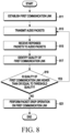
- FIG. 8 is a flowchart illustrating an example of an operating process of an external electronic device in a wireless communication network according to an embodiment.
- a processor e.g., a processor 120 in FIG. 1 or a processor 304 in FIG. 3 of an external electronic device (e.g., an electronic device 101 in FIG. 1 , or an external electronic device 201 in FIG. 2, FIG. 3 , or FIG. 4 ) may establish a communication link (e.g., a first communication link) with a first electronic device (e.g., a first electronic device 202 in FIG. 2 or FIG. 4 ) via a communication circuit (e.g., a communication module 190 in FIG. 1 or a communication circuit 302 in FIG. 3 ).
- a communication link e.g., a first communication link
- a communication circuit e.g., a communication module 190 in FIG. 1 or a communication circuit 302 in FIG. 3 .
- the processor may also establish a communication link (e.g., a second communication link) with a second electronic device (e.g., a second electronic device 204 in FIG. 2 or FIG. 4 ), so operations 813 to 821 applied to the first communication link may also be applied to the second communication link.
- operations 813 to 821 applied to the first communication link may also be applied to a third communication link established between the first electronic device and a second electronic device (e.g., a second electronic device 204 in FIG. 2 or FIG. 4 ).
- the first communication link may be a CIS connection.
- Each CIS may be associated with asynchronous connection-oriented (ACL), and a CIS supports variable size-audio packets and supports transmission of one or more audio packets at each isochronous event.
- An acknowledgment protocol may be used for improving reliability of audio packet delivery in the CIS.
- the processor may allocate an identifier to each CIS, and an identifier allocated to the CIS may be a CIS_ID.
- the processor may transmit the CIS_ID to the first electronic device via the communication circuit.
- Each CIS may be defined by the following parameters:
- Framed may indicate whether a CIS delivers framed data or unframed data.
- a value of Framed can be the same in both directions.
- parameters such as the ISO _Interval, the Sub_Interval, the SE_Length, the Max_PDU, the Max_SDU, the MPT M and the MPT S , the NSE, the BN and the FT, and the Framed may not be changed during lifetime of the CIS.
- a processor which establishes the first communication link with the first electronic device, may transmit audio packets to the first electronic device via the communication circuit in the established first communication link in operation 813.
- a processor which transmits the audio packets may receive response packets to the audio packets via the communication circuit in the first communication link in operation 815.
- a response packet may be an acknowledgment (ACK) packet or a non-acknowledgment (NACK) packet.
- a processor which receives the response packets to the audio packets may identify quality of the first communication link based on the received response packets in operation 817.
- the processor may transmit audio packets during an evaluation period, and identify the quality of the first communication link based on response packets received for the audio packets transmitted during the evaluation period.
- the evaluation period may include a set number of ISO_Intervals. The number of ISO_Intervals included in the evaluation period may vary according to a situation of a wireless communication network, and the evaluation period may be implemented in a form which includes not only ISO_Intervals but also other types of time intervals. The evaluation period will be described in more detail with reference to FIGS. 15a and 15b below.
- the processor may identify the quality of the first communication link based on at least one of a moving average value, the number of unacked packets during the evaluation period, the number of flushed packets during the evaluation period, a noise level, a BLER, an FER, a BER, a PER, an RSSI, an SINR, an SNR, packet retransmission time, the number of transmitted packets per unit time, or a retransmission rate.
- the quality of the communication link may be less than threshold quality.
- the processor may identify the quality of the first communication link based on the EMA value in operation 817.
- the processor which identifies the quality of the first communication link may check whether the quality of the first communication link is higher than or equal to the threshold quality in operation 819. For example, if the EMA value of the first communication link is less than or equal to a threshold EMA value, the processor may identify that the quality of the first communication link is greater than or equal to the threshold quality, and conversely, if the EMA value of the first communication link is greater than the threshold EMA value, the processor may identify that the quality of the first communication link is lower than the threshold quality.
- the threshold EMA value may be determined based on a size of a payload included in an audio packet.
- a size of a payload in which high-sound quality audio data e.g., audio data whose sound quality is higher than or equal to threshold sound quality
- a size of a payload including low-sound quality audio data e.g., audio data whose sound quality is lower than the threshold sound quality.
- a threshold EMA value determined for a case where the size of the payload included in the audio packet is larger than or equal to a threshold size may be different from a threshold EMA value determined for a case where the size of the payload included in the audio packet is smaller than the threshold size.
- the threshold EMA value determined for the case where the size of the payload included in the audio packet is larger than or equal to the threshold size may be less than the threshold EMA value determined for the case where the size of the payload included in the audio packet is smaller than the threshold size.
- the processor may return to operation 813.
- the processor may perform a packet drop operation on the first communication link in operation 821.
- the packet drop operation may be an operation of dropping (for example, discarding) audio packets before flush points for audio packets in a communication link whose quality is lower than threshold quality, and transmitting drop indication packets indicating a drop for the audio packets.
- a drop indication packet may include information indicating an audio packet drop.
- the packet drop operation is described as follows.
- Threshold quality may be quality of a communication link corresponding to a threshold value.
- the threshold may be set based on a retransmission rate during an evaluation interval, an EMA value of the retransmission rate, the number of unacked packets, or the number of flushed packets.
- the quality of the communication link may be classified into first quality (e.g., Good RF quality), second quality (e.g., Bad RF quality), and third quality (e.g., Very Bad RF).
- the first quality may mean quality of the communication link which is greater than or equal to a first threshold value
- the second quality may mean quality of the communication link which is less than the first threshold value and greater than or equal to a second threshold value
- the third quality may mean quality of the communication link which is less than the second threshold value.
- the processor may perform a packet drop operation corresponding to the corresponding quality, and control (or adjust) a flush point.
- First quality 1701 e.g., Good RF quality
- second quality 1703 e.g., Bad RF quality
- third quality 1705 e.g., Very Bad RF
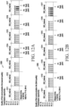
- a retransmission rate during an evaluation interval, an EMA value of the retransmission rate during the evaluation interval, the number of unacked packets during the evaluation interval, and the number of flushed packets during the evaluation interval are illustrated in FIG. 17 .
- a horizontal axis may be a time axis, and a unit thereof may be a second.
- a vertical axis may be a retransmission rate axis, and a unit thereof may be a percentage.
- a graph illustrated in FIG. 17 may be a graph representing quality of a communication link in a case that an external electronic device moves from a strong electric field region to a weak electric field region, and then moves from the weak electric field region to the strong electric field region again.
- a general wireless communication network as described in FIG.
- transmission opportunities are given that are determined based on FT and a flush point set for audio data packets, and therefore, if quality of a communication link is lower than threshold quality, most of transmission opportunities given for a set time period may be given to a first audio packet which is an audio packet firstly transmitted among audio packets transmitted in the set time period (e.g., at least one ISO_Interval) in the communication link whose quality is less than the threshold quality.
- a packet drop operation of dropping audio packets transmitted in a communication link whose quality is less than threshold quality before flush points set for the corresponding audio packets. In this way, by making it possible to drop the audio packets transmitted in the communication link whose quality is less than the threshold quality before the flush points set for the corresponding audio packets, the imbalance in terms of transmission opportunities may be resolved, so service quality may be improved.
- the processor may perform a packet drop operation at a set packet drop ratio. For example, the processor may perform the packet drop operation at the packet drop ratio of 2:1 if the quality of the communication link is less than the threshold quality. If the packet drop ratio is 2:1, the processor may drop an audio packet immediately following two audio packets which are successfully transmitted whenever there are the two audio packets which are successfully transmitted. The processor which drops the corresponding audio packet may generate a drop indication packet which indicates audio packet drop, and transmit the generated drop indication packet to the first electronic device via the communication circuit. As another example, the processor may perform the packet drop operation at a packet drop ratio of 1:1 if the quality of the communication link is less than the threshold quality.
- the processor may drop an audio packet immediately following one audio packet which is successfully transmitted whenever there is the one audio packet which is successfully transmitted.
- the processor which drops the corresponding audio packet may generate a drop indication packet, and transmit the generated drop indication packet to the first electronic device via the communication circuit.
- the drop indication packet may be implemented with an empty (E) packet, may be implemented with a null (N) packet, or may be implemented with a special packet.
- the special packet may be implemented with a packet predefined between an external electronic device (e.g., a central device) and the first electronic device (e.g., a first peripheral device), or may be implemented with at least a part of a reserved for future use (RFU) field included in an ISO header field included in an ISO data packet (e.g., an audio packet).
- information indicating that a corresponding packet is a drop indication packet may be included in an RFU field included in a header field of a null packet, and in this case, the null packet including the information indicating that the packet is the drop indication packet may be a special packet.
- the special packet may include a header field and a payload field, and a payload length of the payload field may be set to 1 byte and a set value (e.g., 0xff) may be included in the payload field.
- the special packet including the set value may be the drop indication packet.
- the payload included in the special packet may include information associated with audio packet drop.
- the information associated with the audio packet drop may include at least one of information indicating that the corresponding packet is the drop indication packet, information requesting to perform a packet drop operation in a communication link via which the special packet is transmitted, or information about a time point at which the packet drop operation is to be performed in the communication link via which the special packet is transmitted.
- FIG. 9 is a flowchart illustrating an example of an operating process of a first electronic device in a wireless communication network according to an embodiment.
- a processor e.g., a processor 410 in FIG. 4 of a first electronic device (e.g., a first electronic device 202 in FIG. 2 or FIG. 4 ) may establish a communication link (e.g., a first communication link) with an external electronic device (e.g., an electronic device 101 in FIG. 1 , or an external electronic device 201 in FIG. 2, FIG. 3 , or FIG. 4 ) via a communication circuit (e.g., a communication circuit 420 in FIG. 4 ).
- a communication link e.g., a first communication link
- an external electronic device e.g., an electronic device 101 in FIG. 1 , or an external electronic device 201 in FIG. 2, FIG. 3 , or FIG. 4
- a communication circuit e.g., a communication circuit 420 in FIG. 4
- the processor may also establish a communication link (e.g., a third communication link) with a second electronic device (e.g., a second electronic device 204 in FIG. 2 or FIG. 4 ), so operations 913 to 917 applied to the first communication link may also be applied to the third communication link.
- the operations 913 to 917 applied to the first communication link may also be applied to the third communication link established between the first electronic device and the second electronic device (e.g., the second electronic device 204 in FIG. 2 or FIG. 4 ).
- An operation of establishing the first communication link between the first electronic device and the external electronic device may be implemented to be similar to or substantially the same as an operation of establishing the first communication link between the external electronic device and the first electronic device described in FIG. 8 , so a detailed description thereof will be omitted.
- the processor which establishes the first communication link with the external electronic device may receive audio packets via the communication circuit in the established first communication link in operation 913.
- the processor may identify whether the received audio packets include a drop indication packet (for example, may identify whether the drop indication packet is received).
- the drop indication packet may be implemented to be similar to or substantially the same as that described in FIG. 8 , so a detailed description thereof will be omitted.
- the processor may perform an audio playback operation for the received audio packets in operation 917.
- the processor may identify that a packet drop operation is being performed for the first communication link, and thus an audio packet transmitted in the first communication link is dropped in operation 919.
- the processor which identifies that the audio packet is dropped, may perform a packet loss concealment (PLC) operation on the dropped audio packet to restore the dropped audio packet, and may perform an audio playback operation in operation 917.
- PLC packet loss concealment
- the PLC operation may be an operation for restoring an audio packet.
- the external electronic device may perform the packet drop operation on the first communication link, as described in FIG. 8 .
- the wireless communication network since transmission opportunities determined based on FT and flush points are given to audio data packets, as described in FIG. 7 , if quality of a communication link is lower than threshold quality, most of the transmission opportunities given for a set time period may be given to a first audio packet, which is an audio packet firstly transmitted among audio packets transmitted in the set time period in the communication link, and only the minimum transmission opportunities may be given to the remaining audio packets after the first audio packet. This imbalance in terms of transmission opportunities may ultimately result in service quality degradation, and as described in FIG.
- the external electronic device may perform the packet drop operation on the communication link whose quality is lower than the threshold quality to drop (for example, discard) audio packets before flush points set for the audio packets and transmit a drop indication packet indicating audio packet drop.
- the processor which receives the drop indication packet transmitted from the external electronic device may identify that an audio packet is dropped because the drop indication packet is received even if the flush points for the audio packets have not been reached, and may perform a PLC operation on the dropped audio packet to restore the dropped audio packet, and thus receive audio packets following the dropped audio packet.
- a response packet may be an ACK packet or a NACK packet.
- FIGS. 10a and 10b are diagrams illustrating another example of transmissions of audio packets in a wireless communication network according to an embodiment.
- NSE 6
- FT 5
- BN 2
- one ISO_Interval may include at least 6 sub-events, and sub-events included in each of an ISO_Interval 1011 to an ISO_Interval 1017 may be a first sub-event to a sixth sub-event according to orders thereof.
- the transmissions 1000 and 1005 of the audio packets illustrated in FIGS. 10a and 10b may be transmissions of audio packets in a communication link established between an audio source device and a first audio sink device.
- the audio source device may be an external electronic device (e.g., an electronic device 101 in FIG. 1 , or an external electronic device 201 in FIG. 2, FIG. 3 , or FIG. 4 )
- the first audio sink device may be a first electronic device (e.g., a first electronic device 202 in FIG. 2 or FIG. 4 )
- the communication link may be a first communication link established between the external electronic device and the first electronic device.
- a packet P0 may not be transmitted normally in the first ISO_Interval 1011.
- a flush point for the packet P0 may be located at a third sub-event in the fifth ISO_Interval 1015.
- a flush point for a packet Pn is illustrated in a form of "Pn flush point", where n may be integers greater than or equal to 0.
- a flush point for the packet P1 may be located at a sixth sub-event of the fifth ISO_Interval 1015
- a flush point for the packet P2 may be located at a third sub-event of the sixth ISO_Interval 1016
- a flush point for the packet P3 may be located at a sixth sub-event of the sixth ISO_Interval 1016
- the flush point for the packet P4 may be located at a third sub-event of the seventh ISO_Interval 1017
- the flush point for the packet P5 may be located at a sixth sub-event of the seventh ISO_Interval 1017.
- a packet drop operation may be performed for the communication link whose quality is less than the threshold quality.
- an external electronic device may determine to perform the packet drop operation for the communication link whose quality is less than the threshold quality, and based on the determination, may drop a corresponding audio packet and then transmit a drop indication packet.
- the external electronic device may drop a corresponding audio packet before a flush point at a set packet drop ratio.
- transmissions of audio packets illustrated by reference numeral 1000 may be transmissions of audio packets if the set packet drop ratio is 2: 1.
- the packet drop ratio may be 2:1 if quality of a communication link is lower than first threshold quality (for example, if the quality of the communication link is second quality).
- transmissions of audio packets illustrated by reference numeral 1005 may be transmissions of audio packets if the set packet drop ratio is 1: 1.
- the packet drop ratio may be 1:1 if the quality of the communication link is lower than second threshold quality (for example, if the quality of the communication link is third quality).
- the second quality may be good quality compared to the third quality
- first quality may be quality which allows normal transmission and reception of audio packets on the corresponding communication link.
- the external electronic device may drop an audio packet immediately following two audio packets which are successfully transmitted whenever there are the two audio packets which are successfully transmitted, and transmit (1000) a drop indication packet.
- Transmissions 1000 of audio packets if the set ratio is 2:1 are specifically described as follows.
- the external electronic device may receive an ACK packet for a packet P0 in the third sub-event of the first ISO_Interval 1011, and may receive an ACK packet for a packet P1 in the fifth sub-event of the third ISO_Interval 1013.
- "ACK" may represent that an ACK packet is received at a corresponding time point.
- FIGS. 10a and 10b it is assumed that a drop indication packet is implemented with an E packet.
- the external electronic device may drop an audio packet (e.g., a packet P2) immediately following two audio packets which are successfully transmitted, if the two audio packets (e.g., the packet P0 and the packet P1) are successfully transmitted.
- an audio packet e.g., a packet P2
- the two audio packets e.g., the packet P0 and the packet P1 are successfully transmitted.
- the external electronic device which drops the packet P2 may transmit a drop indication packet 1020 for the packet P2 in the sixth sub-event of the third ISO_Interval 1013.
- the external electronic device may receive an ACK packet for the drop indication packet 1020 for the packet P2 in the sixth sub-event of the third ISO_Interval 1013.
- the external electronic device may receive an ACK packet for a packet P3 in the second sub-event of the fifth ISO_Interval 1015, and may receive an ACK packet for a packet P4 in the first sub-event of the sixth ISO_Interval 1016.
- the external electronic may drop an audio packet (e.g., a packet P5) immediately following two audio packets which are successfully transmitted, if the two audio packets (e.g., the packet P3 and the packet P4) are successfully transmitted.
- the external electronic device which drops the packet P5 may transmit a drop indication packet 1030 for the packet P5 in the second sub-event of the sixth ISO_Interval 1016.
- the external electronic device may receive an ACK packet for the drop indication packet 1030 for the packet P5 in the second sub-event of the sixth ISO_Interval 1016.
- the external electronic device may receive an ACK packet for a packet P6 in the sixth sub-event of the sixth ISO_Interval 1016, and may receive an ACK packet for a packet P7 in the fifth sub-event of the seventh ISO_Interval 1017.
- the external electronic may drop an audio packet (e.g., a packet P8) immediately following two audio packets which are successfully transmitted, if the two audio packets (e.g., the packet P6 and the packet P7) are successfully transmitted.
- the external electronic device which drops the packet P8 may transmit a drop indication packet 1040 for the packet P8 in the sixth sub-event of the seventh ISO_Interval 1017.
- the external electronic device may receive an ACK packet for the drop indication packet 1040 for the packet P8 in the sixth sub-event of the seventh ISO_Interval 1017.
- the external electronic device may drop an audio packet immediately following one audio packet which is successfully transmitted when there is the one audio packet which is successfully transmitted, and transmit (1005) a drop indication packet.
- Transmissions 1005 of audio packets if the set ratio is 1:1 are specifically described as follows.
- the external electronic device may receive an ACK packet for a packet P0 in the fifth sub-event of the second ISO_Interval 1012. If one audio packet (e.g., the packet P0) is successfully transmitted, the external electronic device may drop an audio packet (e.g., a packet P1) immediately following the one audio packet which is successfully transmitted.
- an audio packet e.g., a packet P1 immediately following the one audio packet which is successfully transmitted.
- the external electronic device which drops the packet P1 may transmit a drop indication packet 1060 for the packet P1 in the sixth sub-event of the second ISO_Interval 1012.
- the external electronic device may receive an ACK packet for the drop indication packet 1060 for the packet P1 in the sixth sub-event of the second ISO_Interval 1012.
- the external electronic device may receive an ACK packet for a packet P2 in the second sub-event of the fourth ISO_Interval 1014.
- the external electronic device which receives the ACK packet for the packet P2 may determine to drop an immediately following audio packet (e.g., a packet P3).
- the external electronic device which drops the packet P3 may transmit a drop indication packet 1070 for the packet P3 in the third sub-event of the fourth ISO_Interval 1014.
- the external electronic device may receive an ACK packet for the drop indication packet 1070 for the packet P3 in the third sub-event of the fourth ISO_Interval 1014.
- the external electronic device may receive an ACK packet for a packet P4 in the second sub-event of the sixth ISO_Interval 1016.
- the external electronic device which receives the ACK packet for the packet P4 may determine to drop an immediately following audio packet (e.g., a packet P5).
- the external electronic device which drops the packet P5 may transmit a drop indication packet 1080 for the packet P5 in the third sub-event of the sixth ISO_Interval 1016.
- the external electronic device may receive an ACK packet for the drop indication packet 1080 for the packet P5 in the third sub-event of the sixth ISO_Interval 1016.
- FIG. 11 is a diagram illustrating still another example of transmissions of audio packets in a wireless communication network according to an embodiment.
- NSE 6
- FT 5
- BN 2
- one ISO_Interval may include at least 6 sub-events, and sub-events included in each of an ISO_Interval 1111 to an ISO_Interval 1117 may be a first sub-event to a sixth sub-event according to orders thereof.
- the transmissions of the audio packets illustrated in FIG. 11 may be transmissions of audio packets in a communication link established between an audio source device and a first audio sink device.
- the audio source device may be an external electronic device (e.g., an electronic device 101 in FIG. 1 , or an external electronic device 201 in FIG. 2, FIG. 3 , or FIG. 4 )
- the first audio sink device may be a first electronic device (e.g., a first electronic device 202 in FIG. 2 or FIG. 4 )
- the communication link may be a first communication link established between the external electronic device and the first electronic device.
- a flush point for the packet P0 may be located at a third sub-event in the fifth ISO_Interval 1115.
- a flush point for a packet Pn is illustrated in a form of "Pn flush point", where n may be integers greater than or equal to 0.
- a flush point for the packet P1 may be located at a sixth sub-event of the fifth ISO_Interval 1115
- a flush point for the packet P2 may be located at a third sub-event of the sixth ISO_Interval 1116
- a flush point for the packet P3 may be located at a sixth sub-event of the sixth ISO_Interval 1116
- the flush point for the packet P4 may be located at a third sub-event of the seventh ISO_Interval 1117
- the flush point for the packet P5 may be located at a sixth sub-event of the seventh ISO_Interval 1117.
- a transmission opportunity is expressed as a "Tx packet count”.
- the disclosure may provide a scheme (e.g., a flush point adjustment operation) for adjusting a flush point for an audio packet based on quality of a communication link.
- a scheme e.g., a flush point adjustment operation
- an audio service is used as an example to describe an embodiment, but the disclosure may be applied not only to the audio service but also to all coordinated communication services which a first electronic device, a second electronic device, and an external electronic device may provide in cooperation with each other.
- the flush point for the audio packet may be adjusted based on various algorithms.
- a location of a sub-event including a flush point for each of the packets P0, P1, P2, P3, P4, and P5 may be represented as shown in Table 1 below.
- Table 1 Packet P0 Packet P1 Packet P2 Packet P3 Packet P4 Packet P5 First quality 0 0 0 0 0 0 0 0 Second quality -6 -6 -3 -3 0 0 Third quality -15 -12 -9 -6 -3 0
- the first quality may be quality of a communication link which is higher than or equal to first threshold quality.
- the second quality may be quality of the communication link which is lower than the first threshold quality and higher than or equal to second threshold quality.
- the third quality may be quality of the communication link which is lower than the second threshold quality.
- the first quality may be the best quality.
- Locations of sub-events including flush points for audio packets in a case where the quality of the communication link is the second quality may be different from locations of sub-events including flush points for audio packets in a case where the quality of the communication link is the first quality. If the quality of the communication link changes from the first quality to the second quality (for example, if the quality of the communication link becomes bad), flush points for audio packets may be adjusted.
- the location of the sub-event including the flush point for the packet P0 may be changed from “0" to "-6”
- the location of the sub-event including the flush point for the packet P1 may be changed from “0” to "-6”
- the location of the sub-event including the flush point for the packet P2 may be changed from “0" to "-3”
- the location of the sub-event including the flush point for the packet P3 may be changed from “0" to "-3”
- the location of the sub-event including the flush point for the packet P4 may be maintained as "0”
- the location of the sub-event including the flush point for the packet P5 may be maintained as "0".
- a location of a sub-event including a flush point may be moved to precede in a time domain by -3 and -6 in units of two audio packets, which is the same number as BN, compared to a case where the quality of the communication link is the first quality.
- Locations of sub-events including flush points for packets if the quality of the communication link is the third quality may be different from locations of sub-events including flush points for the packets if the quality of the communication link is the first quality or locations of sub-events including flush points for the packets if the quality of the communication link is the second quality. If the quality of the communication link changes from the first quality to the second quality or the third quality, or if the quality of the communication link changes from the second quality to the third quality (for example, if the quality of the communication link becomes bad), the flush points for the audio packets may be adjusted.
- the location of the sub-event including the flush point for the packet P0 may be changed from “0" to "-15”
- the location of the sub-event including the flush point for the packet P1 may be changed from “0" to "-12”
- the location of the sub-event including the flush point for the packet P2 may be changed from “0” to "-9”
- the location of the sub-event including the flush point for the packet P3 may be changed from “0" to "-6”
- the location of the sub-event including the flush point for the packet P4 may be changed from "0" to "-3”
- the location of the sub-event including the flush point for the packet P5 may be maintained as "0".
- transmission opportunities for audio packets may be maintained appropriately even though the quality of the communication link lower than threshold quality, so an issue of excessive transmission opportunities being given only to specific audio packets may be resolved.
- FIGS. 12a and 12b are diagrams illustrating still another example of transmissions of audio packets in a wireless communication network according to an embodiment.
- NSE 6
- FT 5
- BN 2
- one ISO_Interval may include at least 6 sub-events, and sub-events included in each of an ISO_Interval 1211 to an ISO_Interval 1217 may be a first sub-event to a sixth sub-event according to orders thereof.
- the audio source device may be an external electronic device (e.g., an electronic device 101 in FIG. 1 , or an external electronic device 201 in FIG. 2, FIG. 3 , or FIG. 4 )
- the first audio sink device may be a first electronic device (e.g., a first electronic device 202 in FIG. 2 or FIG. 4 )
- the communication link may be a first communication link established between the external electronic device and the first electronic device.
- a packet P0 may not be transmitted normally in the first ISO_Interval 1211.
- a flush point for the packet P0 may be located at a third sub-event in the fifth ISO_Interval 1215.
- a flush point for a packet Pn is illustrated in a form of "Pn flush point", where n may be integers greater than or equal to 0.
- a flush point adjustment operation may be performed for the corresponding communication link.
- flush points for audio packets may be adjusted, and audio packets may be transmitted based on the adjusted flush points.
- transmissions of audio packets illustrated by reference numeral 1200 may be transmissions of audio packets if the quality of the communication link is second quality (for example, if the quality of the communication link is lower than first threshold quality)
- transmissions of audio packets illustrated by reference numeral 1205 may be transmissions of audio packets if the quality of the communication link is third quality (for example, if the quality of the communication link is lower than second threshold quality).
- the external electronic device may adjust flush points for audio packets and transmit (1200) the audio packets based on the adjusted flush points.
- the transmissions 1200 of the audio packets if the quality of the communication link is the second quality are described in detail as follows.
- default flush points set for packets P0 to P5 may be used.
- the default flush point for the packet P0 may be located at a third sub-event in the fifth ISO_Interval 1215
- the default flush point for the packet P1 may be located at a sixth sub-event of the fifth ISO_Interval 1215
- the default flush point for the packet P2 may be located at a third sub-event of the sixth ISO_Interval 1216
- the default flush point for the packet P3 may be located at a sixth sub-event of the sixth ISO_Interval 1216
- the default flush point for the packet P4 may be located at a third sub-event of the seventh ISO_Interval 1217
- the default flush point for the packet P5 may be located at a sixth sub-event of the seventh ISO_Interval 1217.
- the external electronic device may adjust the flush points for the packets P0 to P5.
- the adjusted flush point for the packet P0 may be located at the third sub-event in the fourth ISO_Interval 1214
- the adjusted flush point for the packet P1 may be located at the sixth sub-event of the fourth ISO_Interval 1214
- the adjusted flush point for the packet P2 may be located at the sixth sub-event of the fifth ISO_Interval 1215
- the adjusted flush point for the packet P3 may be located at the third sub-event of the sixth ISO_Interval 1216
- the adjusted flush point for the packet P4 may be located at the third sub-event of the seventh ISO_Interval 1217
- the adjusted flush point for the packet P5 may be located at the sixth sub-event of the seventh ISO_Interval 1217.
- the external electronic device may adjust flush points for audio packets and transmit (1205) the audio packets based on the adjusted flush points.
- the transmission 1205 of the audio packets if the quality of the communication link is the third quality is specifically described as follows.
- Default flush points set for the packets P0 to P5 in a wireless communication network may be the same as the default flush points set for the packets P0 to P5 described if the quality of the communication link is the second quality, so a detailed description thereof will be omitted. According to an embodiment, if the quality of the communication link is the third quality, the external electronic device may adjust the flush points for the packets P0 to P5.
- the adjusted flush point for the packet P0 may be located at the sixth sub-event in the second ISO_Interval 1212
- the adjusted flush point for the packet P1 may be located at the sixth sub-event of the third ISO_Interval 1213
- the adjusted flush point for the packet P2 may be located at the sixth sub-event of the fourth ISO_Interval 1214
- the adjusted flush point for the packet P3 may be located at the sixth sub-event of the fifth ISO_Interval 1215
- the adjusted flush point for the packet P4 may be located at the sixth sub-event of the sixth ISO_Interval 1216
- the adjusted flush point for the packet P5 may be located at the sixth sub-event of the seventh ISO_Interval 1217.
- FIG. 13 is a flowchart illustrating another example of an operating process of an external electronic device in a wireless communication network according to an embodiment.
- a processor e.g., a processor 120 in FIG. 1 or a processor 304 in FIG. 3 of an external electronic device (e.g., an electronic device 101 in FIG. 1 , or an external electronic device 201 in FIG. 2, FIG. 3 , or FIG. 4 ) may establish a communication link (e.g., a first communication link) with a first electronic device (e.g., a first electronic device 202 in FIG. 2 or FIG. 4 ) via a communication circuit (e.g., a communication module 190 in FIG. 1 or a communication circuit 302 in FIG. 3 ).
- a communication link e.g., a first communication link
- a communication circuit e.g., a communication module 190 in FIG. 1 or a communication circuit 302 in FIG. 3 .
- the processor may also establish a communication link (e.g., a second communication link) with a second electronic device (e.g., a second electronic device 204 in FIG. 2 or FIG. 4 ), so operations 1313 to 1321 applied to the first communication link may also be applied to the second communication link.
- operations 1313 to 1321 applied to the first communication link may also be applied to a third communication link established between the first electronic device and a second electronic device (e.g., a second electronic device 204 in FIG. 2 or FIG. 4 ).
- the first communication link may be a CIS connection
- the operation in which the processor establishes the first communication link may be implemented to be similar to or substantially the same as an operation in which an electronic device establishes a first communication link as described in operation 811 in FIG. 8 , so a detailed description thereof will be omitted.
- a processor which establishes the first communication link with the first electronic device, may transmit audio packets to the first electronic device via the communication circuit in the established first communication link in operation 1313.
- a processor which transmits the audio packets may receive response packets to the audio packets via the communication circuit in the first communication link in operation 1315.
- a response packet may be an ACK packet or a NACK packet.
- a processor which receives the response packets to the audio packets may identify quality of the first communication link based on the received response packets in operation 1317.
- the processor may transmit audio packets during an evaluation period, and identify the quality of the first communication link based on response packets received for the audio packets transmitted during the evaluation period.
- the evaluation period may include a set number of ISO_Intervals. The number of ISO_Intervals included in the evaluation period may vary according to a situation of a wireless communication network, and the evaluation period may be implemented in a form which includes not only ISO Intervals but also other types of time intervals. The evaluation period will be described in more detail with reference to FIGS. 15a and 15b below.
- the processor may identify the quality of the first communication link based on at least one of a moving average value, the number of unacked packets during the evaluation period, the number of flushed packets during the evaluation period, a noise level, a BLER, an FER, a BER, a PER, an RSSI, an SINR, an SNR, packet retransmission time, the number of transmitted packets per unit time, or a retransmission rate.
- the moving average value is an EMA value
- the processor may identify the quality of the first communication link based on the EMA value in operation 1317.
- the operation in which the processor identifies the quality of the first communication link based on the received response packets may be implemented to be similar to or substantially the same as an operation in which the processor identifies the quality of the first communication link based on the received response packets as described in operation 817 in FIG. 8 , so a detailed description thereof will be omitted.
- the processor which identifies the quality of the first communication link may, in operation 1319, check whether the quality of the first communication link is higher than or equal to threshold quality. For example, the processor may identify that the quality of the first communication link is higher than or equal to the threshold quality if an EMA value of the first communication link is less than or equal to a threshold EMA value, and conversely, may identify that the quality of the first communication link is lower than the threshold quality if the EMA value of the first communication link is greater than the threshold EMA value.
- the threshold EMA value may be determined based on a size of a payload included in an audio packet.
- a size of a payload including high-sound quality audio data may be larger than a size of a payload including low-sound quality audio data (e.g., audio data whose sound quality is lower than the threshold sound quality).
- a threshold EMA value determined if the size of the payload included in the audio packet is greater than or equal to a threshold size may be different from a threshold EMA value determined if the size of the payload included in the audio packet is less than the threshold size.
- the threshold EMA value determined if the size of the payload included in the audio packet is greater than or equal to the threshold size may be less than the threshold EMA value determined if the size of the payload included in the audio packet is less than the threshold size.
- the processor may return to operation 1313.
- a flush point adjustment operation may be an operation of adjusting flush points for audio packets in a communication link whose quality is lower than threshold quality.
- the flush point adjustment operation may be an operation of changing the flush points for the audio packets in the communication link whose quality is lower than the threshold quality from default flush points to adjusted flush points.
- transmission opportunities determined based on FT and a flush point may be given to audio data packets, and therefore, if the quality of the communication link is lower than the threshold quality, most of transmission opportunities given for a set time period may be given to a first audio packet which is an audio packet firstly transmitted among audio packets transmitted in the set time period (e.g., at least one ISO_Interval) in the communication link whose quality is lower than the threshold quality.
- a flush point adjustment operation for adjusting (for example, changing) flush points for audio packets transmitted in a communication link whose quality is lower than threshold quality. In this way, by adjusting the flush points for the audio packets transmitted in the communication link whose quality is lower than the threshold quality, the imbalance in terms of transmission opportunities may be resolved, and thus the service quality may be improved.
- the processor may adjust flush points for audio packets transmitted in the first communication link based on NSE and BN set for the first communication link.
- a scheme of adjusting the flush points for the audio packets may be implemented to be similar to or substantially the same as a scheme of adjusting flush points for audio packets described in Table 1, so a detailed description thereof will be omitted.
- the first electronic device may identify whether the flush points for the audio packets are adjusted based on a sequence number (SN) of a received audio packet, even though the first electronic device does not receive separate information associated with the flush points for the audio packets adjusted by the processor.
- SN sequence number
- the processor may inform the first electronic device about the adjusted flush points via a communication circuit. For example, the processor may generate a packet including information associated with the adjusted flush points, and transmit the generated packet to the first electronic device via the communication circuit. In this case, the first electronic device may identify the adjusted flush points for the audio packets transmitted via the first communication link based on the information associated with the adjusted flush points included in the received packet, and receive audio packets based on the identified adjusted flush points for the audio packets.
- FIGS. 14a and 14b are diagrams illustrating still another example of transmissions of audio packets in a wireless communication network according to an embodiment.
- NSE 6
- FT 5
- BN 2
- one ISO_Interval may include at least 6 sub-events, and sub-events included in each of an ISO_Interval 1411 to an ISO_Interval 1417 may be a first sub-event to a sixth sub-event according to orders thereof.
- the transmissions 1400 and 1405 of the audio packets illustrated in FIGS. 14a and 14b may be transmissions of audio packets in a communication link established between an audio source device and a first audio sink device.
- the audio source device may be an external electronic device (e.g., an electronic device 101 in FIG. 1 , or an external electronic device 201 in FIG. 2, FIG. 3 , or FIG. 4 )
- the first audio sink device may be a first electronic device (e.g., a first electronic device 202 in FIG. 2 or FIG. 4 )
- the communication link may be a first communication link established between the external electronic device and the first electronic device.
- a default flush point for the packet P0 may be located at a third sub-event in the fifth ISO_Interval 1415
- a default flush point for the packet P1 may be located at a sixth sub-event of the fifth ISO_Interval 1415
- a default flush point for the packet P2 may be located at a third sub-event of the sixth ISO_Interval 1416
- a default flush point for the packet P3 may be located at a sixth sub-event of the sixth ISO_Interval 1416
- a default flush point for the packet P4 may be located at a third sub-event of the seventh ISO_Interval 1417
- a default flush point for the packet P5 may be located at a sixth sub-event of the seventh ISO_Interval 1417.
- a flush point for a packet Pn is illustrated in the form of a "Pn flush point", where
- threshold quality e.g., first threshold quality or second threshold quality
- audio packets may not be transmitted and received normally via the first communication link.
- the external electronic device may perform a packet drop operation to drop corresponding audio packets.
- the external electronic device may maintain a default flush point for each of the packets P0, P1, P2, P3, P4, P5, P6, P7, and P8, but may drop corresponding audio packets based on a packet drop ratio set before the default flush points of the packets P0, P1, P2, P3, P4, P5, P6, P7, and P8 transmitted via the first communication link, and transmit drop indication packets indicating the dropped audio packets, thereby resolving imbalance in terms of transmission opportunities for audio packets transmitted via the first communication link.
- Transmissions of audio packets illustrated by reference numeral 1400 may be transmissions of audio packets if the packet drop ratio applied to the packet drop operation is 2:1.
- the transmissions of the audio packets if the packet drop ratio is 2:1 may be implemented to be similar to or substantially the same as transmissions of audio packets illustrated by reference numeral 1000 in FIGS. 10a and 10b .
- the external electronic device may receive an ACK packet for a packet P0 in the third sub-event of the first ISO_Interval 1411, and may receive an ACK packet for a packet P1 in the fifth sub-event of the third ISO_Interval 1413.
- "ACK" may represent that an ACK packet is received at a corresponding time point.
- FIGS. 14a and 14b it is assumed that a drop indication packet is implemented with an E packet.
- the external electronic device may drop an audio packet (e.g., a packet P2) immediately following two audio packets which are successfully transmitted, if the two audio packets (e.g., the packet P0 and the packet P1) are successfully transmitted.
- an audio packet e.g., a packet P2
- the two audio packets e.g., the packet P0 and the packet P1 are successfully transmitted.
- the external electronic device which drops the packet P2 may transmit a drop indication packet 1420 for the packet P2 in the sixth sub-event of the third ISO_Interval 1413.
- the external electronic device may receive an ACK packet for the drop indication packet 1420 for the packet P2 in the sixth sub-event of the third ISO_Interval 1413.
- the external electronic device may receive an ACK packet for a packet P3 in the second sub-event of the fifth ISO_Interval 1415, and may receive an ACK packet for a packet P4 in the first sub-event of the sixth ISO_Interval 1416.
- the external electronic may drop an audio packet (e.g., a packet P5) immediately following two audio packets which are successfully transmitted, if the two audio packets (e.g., the packet P3 and the packet P4) are successfully transmitted.
- the external electronic device which drops the packet P5 may transmit a drop indication packet 1430 for the packet P5 in the second sub-event of the sixth ISO_Interval 1416.
- the external electronic device may receive an ACK packet for the drop indication packet 1430 for the packet P5 in the second sub-event of the sixth ISO_Interval 1416.
- the external electronic device may receive an ACK packet for a packet P6 in the sixth sub-event of the sixth ISO_Interval 1416, and may receive an ACK packet for a packet P7 in the fifth sub-event of the seventh ISO_Interval 1417.
- the external electronic may drop an audio packet (e.g., a packet P8) immediately following two audio packets which are successfully transmitted, if the two audio packets (e.g., the packet P6 and the packet P7) are successfully transmitted.
- the external electronic device which drops the packet P8 may transmit a drop indication packet 1440 for the packet P8 in the sixth sub-event of the seventh ISO_Interval 1417.
- the external electronic device may receive an ACK packet for the drop indication packet 1440 for the packet P8 in the sixth sub-event of the seventh ISO_Interval 1417.
- Transmissions of audio packets illustrated by reference numeral 1400 may be transmissions of audio packets if the packet drop ratio applied to the packet drop operation is 2:1 and the flush points for the audio packets are not changed.
- transmissions of audio packets illustrated by reference numeral 1405 may be transmissions of audio packets if the packet drop ratio applied to the packet drop operation is 1:1 and the flush points for the audio packets are also changed (for example, if a flush point adjustment operation is performed).
- the external electronic device may perform a packet retransmission operation up to default flush points set for audio packets.
- the external electronic device may not maintain a default flush point for each of the packets P0, P1, P2, P3, P4, P5, P6, P7, and P8, but may newly set a flush point for each of the packets P0, P1, P2, P3, P4, P5, P6, P7, and P8.
- the external electronic device may change flush points of the packets P0, P1, P2, P3, P4, P5, P6, P7, and P8 transmitted via the first communication link, and transmit a drop indication packet indicating audio packet drop before the changed flush points of the packets P0, P1, P2, P3, P4, P5, P6, P7, and P8, thereby resolving imbalance in terms of transmission opportunities for audio packets transmitted via the first communication link.
- Transmissions of audio packets illustrated by reference numeral 1405 may be transmissions of audio packets if the packet drop ratio applied to the packet drop operation is 1:1.
- the transmissions of the audio packets if the packet drop ratio is 1:1 may be implemented to be similar to or substantially the same as transmissions of audio packets illustrated by reference numeral 1005 in FIGS. 10a and 10b .
- the adjusted flush point for the packet P0 may be located at the sixth sub-event in the second ISO_Interval 1412, unlike the default flush point which is located at the third sub-event in the fifth ISO_Interval 1415
- the adjusted flush point for the packet P1 may be located at the sixth sub-event in the third ISO_Interval 1413, unlike the default flush point which is located at the sixth sub-event in the fifth ISO_Interval 1415
- the adjusted flush point for the packet P2 may be located at the sixth sub-event in the fourth ISO_Interval 1414, unlike the default flush point which is located at the third sub-event in the sixth ISO_Interval 1416
- the adjusted flush point for the packet P3 may be located at the sixth sub-event in the fifth ISO_Interval 1415, unlike the default flush point which is located at the sixth sub-event of the sixth ISO_Interval 1416, the adjusted flush point for
- the external electronic device may receive an ACK packet for the packet P0 in the sixth sub-event of the second ISO_Interval 1012. If the external electronic device successfully transmits one audio packet (e.g., the packet P0), the external electronic device may drop an audio packet (e.g., the packet P1) immediately following the one audio packet which is successfully transmitted.
- the external electronic device may receive an ACK packet for the packet P0 in the sixth sub-event of the second ISO_Interval 1012. If the external electronic device successfully transmits one audio packet (e.g., the packet P0), the external electronic device may drop an audio packet (e.g., the packet P1) immediately following the one audio packet which is successfully transmitted.
- the external electronic device which drops the packet P1 may transmit a drop indication packet 1460 for the packet P1 in the first sub-event of the third ISO_Interval 1413.
- the external electronic device may receive an ACK packet for the drop indication packet 1460 for packet P1 in the first sub-event of the third ISO_Interval 1413.
- the external electronic device may receive an ACK packet for the packet P2 in the sixth sub-event of the fourth ISO_Interval 1414.
- the external electronic device which receives the ACK packet for the packet P2 may drop an immediately following audio packet (e.g., the packet P3).
- the external electronic device which drops the packet P3 may transmit a drop indication packet 1470 for the packet P3 in the first sub-event of the fifth ISO_Interval 1415.
- the external electronic device may receive an ACK packet for the drop indication packet 1470 for the packet P3 in the second sub-event of the fifth ISO_Interval 1415.
- the external electronic device may receive an ACK packet for the packet P4 in the sixth sub-event of the sixth ISO_Interval 1416.
- the external electronic device which receives the ACK packet for the packet P4 may drop an immediately following audio packet (e.g., the packet P5).
- the external electronic device which drops the packet P5 may transmit a drop indication packet 1480 for the packet P5 in the first sub-event of the seventh ISO_Interval 1417.
- the external electronic device may receive an ACK packet for the drop indication packet 1480 for the packet P5 in the first sub-event of the seventh ISO_Interval 1417.
- FIG. 15a is a diagram illustrating an example of an operation for identifying quality of a communication link in a wireless communication network according to an embodiment.
- one ISO_Interval may include at least six sub-events, and sub-events included in each of an ISO_Interval 1511 to an ISO_Interval 1517 may be, in order, a first sub-event to a sixth sub-event.
- Transmissions of audio packets illustrated in FIG. 15a may be transmissions of audio packets in a communication link established between an audio source device and a first audio sink device.
- the audio source device may be an external electronic device (e.g., an electronic device 101 in FIG. 1 , or an external electronic device 201 in FIG. 2, FIG. 3 , or FIG. 4 )
- the first audio sink device may be a first electronic device (e.g., a first electronic device 202 in FIG. 2 or FIG. 4 )
- the communication link may be a first communication link established between the external electronic device and the first electronic device.
- the external electronic device may transmit audio packets during an evaluation period, and identify quality of the first communication link based on response packets received for the audio packets transmitted during the evaluation period.
- the evaluation period may include a set number of ISO_Intervals. The number of ISO_Intervals included in the evaluation period may vary according to a situation of the wireless communication network, and the evaluation period may be implemented in a form that includes not only ISO Intervals but also other types of time intervals.
- channel quality may be represented by at least one of a moving average value, the number of unacked packets during the evaluation interval, the number of flushed packets during the evaluation interval, a noise level, a BLER, an FER, a BER, a PER, an RSSI, an SINR, an SNR, packet retransmission time, the number of transmitted packets per unit time, or a retransmission rate.
- the channel quality is identified based on an EMA value, which is an example of the moving average value.
- FIG. 15a illustrates three evaluation periods (e.g., a first evaluation period 1520, a second evaluation period 1530, and a third evaluation period 1540).
- the first evaluation period 1520 may include a first ISO_Interval 1511 and a second ISO_Interval 1512.
- the external electronic device may perform a transmission and retransmission operations for a packet P0 in the first evaluation period 1520, but may not receive an ACK packet for the packet P0.
- a retransmission rate N for the first evaluation period 1520 may be 100% in percentage.
- the second evaluation period 1530 may include a third ISO_Interval 1513 and a fourth ISO_Interval 1514.
- the external electronic device may perform a transmission and retransmission operations for a packet P1 and a packet P2 in the second evaluation period 1530.
- the external electronic device may receive an ACK packet for the packet P1 in a sixth sub-event in the third ISO_Interval 1513 and may receive an ACK packet for the packet P2 in a sixth sub-event in the fourth ISO_Interval 1514.
- a retransmission rate N for the second evaluation period 1530 may be 87.5% in percentage.
- the third evaluation period 1540 may include a fifth ISO_Interval 1515 and a sixth ISO_Interval 1516.
- the external electronic device may perform a transmission and retransmission operations for a packet P3 and a packet P8, and perform a transmission for packets P4, P5, P6, and P7 in the third evaluation period 1540.
- the external electronic device may receive an ACK packet for the packet P3 in a fifth sub-event in the fifth ISO_Interval 1515 and may receive an ACK packet for the packet P4 in a sixth sub-event in the fifth ISO_Interval 1515, may receive an ACK packet for the packet P5 in a first sub-event in the sixth ISO_Interval 1516, may receive an ACK packet for the packet P6 in a second sub-event in the sixth ISO_Interval 1516, and may receive an ACK packet for the packet P7 in a third sub-event in the sixth ISO_Interval 1516.
- a retransmission rate N for the third evaluation period 1540 may be 43.75% in percentage.
- the channel quality is identified based on the number of unacked packets (or "unacked packets count”) during the evaluation period or the number of flushed packets (or “flushed packets count”) during the evaluation period.
- FIG. 15b is a diagram illustrating an example of an operation for identifying quality of a communication link in a wireless communication network according to another embodiment.
- one ISO_Interval may include at least six sub-events, and sub-events included in each of an ISO_Interval 1561 to an ISO_Interval 1565 may be, in order, a first sub-event to a sixth sub-event.
- Transmissions of audio packets illustrated in FIG. 15b may be transmissions of audio packets in a communication link established between an audio source device and a first audio sink device.
- the audio source device may be an external electronic device (e.g., an electronic device 101 in FIG. 1 , or an external electronic device 201 in FIG. 2, FIG. 3 , or FIG. 4 )
- the first audio sink device may be a first electronic device (e.g., a first electronic device 202 in FIG. 2 or FIG. 4 )
- the communication link may be a first communication link established between the external electronic device and the first electronic device.
- the external electronic device may transmit audio packets during an evaluation period, and identify quality of the first communication link based on the number of unacked packets (or "unacked packets count") during the evaluation period or the number of flushed packets (or “flushed packets count”) during the evaluation period.
- the evaluation period may include a set number of ISO_Intervals. The number of ISO_Intervals included in the evaluation period may vary according to a situation of the wireless communication network, and the evaluation period may be implemented in a form that includes not only ISO Intervals but also other types of time intervals.
- channel quality may be represented by at least one of a moving average value, the number of unacked packets during the evaluation interval, the number of flushed packets during the evaluation interval, a noise level, a BLER, an FER, a BER, a PER, an RSSI, an SINR, an SNR, packet retransmission time, the number of transmitted packets per unit time, or a retransmission rate.
- a moving average value the number of unacked packets during the evaluation interval
- the number of flushed packets during the evaluation interval a noise level
- a BLER an FER
- a BER a BER
- PER PER
- RSSI an SINR
- SNR packet retransmission time
- packet retransmission time the number of transmitted packets per unit time, or a retransmission rate.
- FIG. 15b illustrates three evaluation periods (e.g., a first evaluation period 1570 and a second evaluation period 1580.
- the first evaluation period 1570 may include a first ISO_Interval 1561 and a second ISO_Interval 1562.
- the external electronic device may perform a transmission and retransmission operations for a packet P0 in the first evaluation period 1560, but may not receive an ACK packet for the packet P0. Since no flush point exists in the first evaluation period 1570, the number of flushed packets during the first evaluation period 1570 may be 0 (zero). Alternatively, since ACK packets for the packet P0 are not received in the first evaluation period 1570, the number of unpacked packets during the first evaluation period 1570 may be 1.
- the second evaluation period 1580 may include a third ISO_Interval 1563, a fourth ISO_Interval 1564, and a fifth ISO_Interval 1565.
- the external electronic device may perform a transmission and retransmission operations for packets P0 to P5 in the second evaluation period 1580. Since no corresponding ACK packet is received for each of the packets P0, P2, P3, P4, and P5 during the second evaluation period 1580, each of the packets P0, P2, P3, P4, and P5 may be an unacked packet. Alternatively, since the packet P1 is not transmitted and discarded during the second evaluation period 1580, the packet P1 may be a flushed packet.
- the external electronic device may identify the number of unacked packets during a specific evaluation period or the number of flushed packets during the specific evaluation period.
- the external electronic device may identify that quality of a corresponding communication link is lower than threshold quality if the number of unacked packets during the specific evaluation period is greater than a threshold-unacked packet number.
- the external electronic device may identify that the quality of the corresponding communication link is lower than the threshold quality if the number of flushed packets during the specific evaluation period is greater than a threshold-flushed packet number.
- FIG. 16 is a flowchart illustrating still another example of an operating process of an external electronic device in a wireless communication network according to an embodiment.
- a processor e.g., a processor 120 in FIG. 1 or a processor 304 in FIG. 3 of an external electronic device (e.g., an electronic device 101 in FIG. 1 , or an external electronic device 201 in FIG. 2, FIG. 3 , or FIG. 4 ) may establish a communication link (e.g., a first communication link) with a first electronic device (e.g., a first electronic device 202 in FIG. 2 or FIG. 4 ) via a communication circuit (e.g., a communication module 190 in FIG. 1 or a communication circuit 302 in FIG. 3 ).
- a communication link e.g., a first communication link
- a communication circuit e.g., a communication module 190 in FIG. 1 or a communication circuit 302 in FIG. 3 .
- the processor may also establish a communication link (e.g., a second communication link) with a second electronic device (e.g., a second electronic device 204 in FIG. 2 or FIG. 4 ), so operations 1613 to 1621 applied to the first communication link may also be applied to the second communication link.
- operations 1613 to 1621 applied to the first communication link may also be applied to a third communication link established between the first electronic device and a second electronic device (e.g., a second electronic device 204 in FIG. 2 or FIG. 4 ).
- the first communication link may be a CIS connection
- the operation in which the processor establishes the first communication link may be implemented to be similar to or substantially the same as an operation in which an electronic device establishes a first communication link as described in operation 811 in FIG. 8 , so a detailed description thereof will be omitted.
- a processor which establishes the first communication link with the first electronic device, may transmit audio packets to the first electronic device via the communication circuit in the established first communication link in operation 1613.
- a processor which transmits the audio packets may receive response packets to the audio packets via the communication circuit in the first communication link in operation 1615.
- a response packet may be an ACK packet or a NACK packet.
- a processor which receives the response packets to the audio packets may identify quality of the first communication link based on the received response packets in operation 1617.
- the processor may transmit audio packets during an evaluation period, and identify the quality of the first communication link based on response packets received for the audio packets transmitted during the evaluation period.
- the evaluation period may include a set number of ISO_Intervals. The number of ISO_Intervals included in the evaluation period may vary according to a situation of a wireless communication network, and the evaluation period may be implemented in a form which includes not only ISO Intervals but also other types of time intervals. The evaluation period may be implemented to be similar to or substantially the same as an evaluation period described in FIGS. 15a and 15b , so a detailed description thereof will be omitted.
- the processor may identify the quality of the first communication link based on at least one of a moving average value, a noise level, a BLER, an FER, a BER, a PER, an RSSI, an SINR, an SNR, packet retransmission time, the number of transmitted packets per unit time, or a retransmission rate.
- a moving average value is an EMA value
- the processor may identify the quality of the first communication link based on the EMA value in operation 1617.
- the operation in which the processor identifies the quality of the first communication link based on the received response packets may be implemented to be similar to or substantially the same as an operation in which the processor identifies the quality of the first communication link based on the received response packets as described in operation 817 in FIG. 8 , so a detailed description thereof will be omitted.
- the processor which identifies the quality of the first communication link may, in operation 1619, check whether the quality of the first communication link is higher than or equal to threshold quality. For example, the processor may identify that the quality of the first communication link is higher than or equal to the threshold quality if an EMA value of the first communication link is less than or equal to a threshold EMA value, and conversely, may identify that the quality of the first communication link is lower than the threshold quality if the EMA value of the first communication link is greater than the threshold EMA value.
- the threshold EMA value may be determined based on a size of a payload included in an audio packet.
- a size of a payload including high-sound quality audio data may be larger than a size of a payload including low-sound quality audio data (e.g., audio data whose sound quality is lower than the threshold sound quality).
- a threshold EMA value determined if the size of the payload included in the audio packet is greater than or equal to a threshold size may be different from a threshold EMA value determined if the size of the payload included in the audio packet is less than the threshold size.
- the threshold EMA value determined if the size of the payload included in the audio packet is greater than or equal to the threshold size may be less than the threshold EMA value determined if the size of the payload included in the audio packet is less than the threshold size.
- the processor may return to operation 1613.
- the processor may perform a packet drop operation and a flush point adjustment operation on the first communication link in operation 1621.
- the packet drop operation may be implemented to be similar to or substantially the same as a packet drop operation described in operation 821 in FIG. 8 , so a detailed description thereof will be omitted.
- the flush point adjustment operation may be implemented to be similar to or substantially the same as a flush point adjustment operation described in operation 1321 in FIG. 13 , so a detailed description thereof will be omitted.
- an operating method of an electronic device may include establishing a communication link with at least one external electronic device (e.g., a first electronic device 202 in FIG. 2 or FIG. 4 , or a second electronic device 204 in FIG. 2 or FIG. 4 ).
- the operating method may further include identifying quality of the communication link.
- the operating method may further include based on the quality of the communication link being less than threshold quality, discarding at least one of packets to be transmitted during a set time period in the communication link.
- the operating method may further include transmitting, to the at least one external electronic device (e.g., the first electronic device 202 in FIG. 2 or FIG. 4 , or the second electronic device 204 in FIG. 2 or FIG. 4 ), a packet indicating that the at least one packet is discarded.
- the at least one external electronic device e.g., the first electronic device 202 in FIG. 2 or FIG. 4 , or the second electronic device 204 in FIG. 2 or FIG. 4 .
- the operating method may further include adjusting flush points which are time points at which the packets to be transmitted during the set time period are set to be discarded, based on the quality of the communication link being less than the threshold quality.
- discarding the at least one of the packets to be transmitted during the set time period in the communication link may include discarding the at least one packet at a time point preceding a flush point, which is a time point at which the at least one packet is set to be discarded, in a time domain.
- identifying the quality of the communication link may include transmitting, to the at least one external electronic device (e.g., the first electronic device 202 in FIG. 2 or FIG. 4 , or the second electronic device 204 in FIG. 2 or FIG. 4 ), packets during another set time period preceding the set time period in a time domain, receiving, from the at least one external electronic device (e.g., the first electronic device 202 in FIG. 2 or FIG. 4 , or the second electronic device 204 in FIG. 2 or FIG. 4 ), during the other set time period, at least one response packet for the packets transmitted during the other set time period, and based on the at least one response packet, identifying the quality of the communication link.
- the at least one external electronic device e.g., the first electronic device 202 in FIG. 2 or FIG. 4 , or the second electronic device 204 in FIG. 2 or FIG. 4
- the at least one external electronic device e.g., the first electronic device 202 in FIG. 2 or FIG. 4 , or the second electronic device
- adjusting the flush points which are the time points at which the packets to be transmitted during the set time period are set to be discarded may include adjusting the flush points for the packets to be transmitted during the set time period, based on a maximum number of sub-events included in each connected isochronous stream (CIS) event included in the set time period and a number of new data packets which may be transmitted within a time interval in which a CIS event occurs.
- CIS connected isochronous stream
- each CIS event may include an opportunity for the electronic device (e.g., the electronic device 101 in FIG. 1 , or the external electronic device 201 in FIG. 2, FIG. 3 , or FIG. 4 ) and the at least one external electronic device (e.g., the first electronic device 202 in FIG. 2 or FIG. 4 , or the second electronic device 204 in FIG. 2 or FIG. 4 ) to exchange a packet.
- the electronic device e.g., the electronic device 101 in FIG. 1 , or the external electronic device 201 in FIG. 2, FIG. 3 , or FIG. 4
- the at least one external electronic device e.g., the first electronic device 202 in FIG. 2 or FIG. 4 , or the second electronic device 204 in FIG. 2 or FIG. 4
- each of the sub-events is used for the electronic device (e.g., the electronic device 101 in FIG. 1 , or the external electronic device 201 in FIG. 2, FIG. 3 , or FIG. 4 ) to transmit a packet and for the at least one external electronic device (e.g., the first electronic device 202 in FIG. 2 or FIG. 4 , or the second electronic device 204 in FIG. 2 or FIG. 4 ) to respond to the electronic device (e.g., the electronic device 101 in FIG. 1 , or the external electronic device 201 in FIG. 2, FIG. 3 , or FIG. 4 ).
- the electronic device e.g., the electronic device 101 in FIG. 1 , or the external electronic device 201 in FIG. 2, FIG. 3 , or FIG. 4
- the electronic device e.g., the electronic device 101 in FIG. 1 , or the external electronic device 201 in FIG. 2, FIG. 3 , or FIG. 4
- the electronic device e.g., the electronic device 101 in FIG. 1 , or the
- discarding the at least one of packets to be transmitted during the set time period in the communication link may include discarding at least one of the packets to be transmitted during the set time period based on a set discard ratio, and the set discard ratio may include a ratio of a number of acknowledgement (ACK) packets continuously received for a set number of packets among the packets to be transmitted during the set time period to a packet indicating that the at least one packet is discarded.
- ACK acknowledgement
- the operating method may further include transmitting, to the at least one external electronic device (e.g., the first electronic device 202 in FIG. 2 or FIG. 4 , or the second electronic device 204 in FIG. 2 or FIG. 4 ), a packet including information associated with the adjusted flush points.
- the at least one external electronic device e.g., the first electronic device 202 in FIG. 2 or FIG. 4 , or the second electronic device 204 in FIG. 2 or FIG. 4 .
- the packet indicating that the at least one packet is discarded may be an empty packet, a null packet, or a special packet.
- an operating method of an electronic device may include establishing a communication link with an external electronic device (e.g., an electronic device 101 in FIG. 1 , or an external electronic device 201 in FIG. 2, FIG. 3 , or FIG. 4 ).
- an external electronic device e.g., an electronic device 101 in FIG. 1 , or an external electronic device 201 in FIG. 2, FIG. 3 , or FIG. 4 .
- the operating method may further include receiving, from the external electronic device (e.g., the electronic device 101 in FIG. 1 , or the external electronic device 201 in FIG. 2, FIG. 3 , or FIG. 4 ), at least one packet during a set time period in the communication link.
- the external electronic device e.g., the electronic device 101 in FIG. 1 , or the external electronic device 201 in FIG. 2, FIG. 3 , or FIG. 4 .
- the operating method may further include identifying whether a packet indicating that the packet is discarded is included in the received at least one packet.
- the operating method may further include performing a recovery operation on a packet corresponding to the packet indicating that the packet is discarded, based on the packet indicating that the packet is discarded being included in the received at least one packet.
- the at least one packet may be discarded at a time point preceding a flush point, which is a time point at which the at least one packet is set to be discarded, in a time domain.
- the at least one packet may be included in the packets transmitted during the set time period.
- the at least one packet may be discarded during the set time period based on a set discard ratio.
- the set discard ratio may include a ratio of a number of acknowledgement (ACK) packets continuously received for a set number of packets among the packets transmitted by the external electronic device (e.g., the electronic device 101 in FIG. 1 , or the external electronic device 201 in FIG. 2, FIG. 3 , or FIG. 4 ) during the set time period to a packet indicating that the packet is discarded.
- ACK acknowledgement
- flush points for the packets transmitted during the set time period may be adjusted by the external electronic device (e.g., the electronic device 101 in FIG. 1 , or the external electronic device 201 in FIG. 2, FIG. 3 , or FIG. 4 ).
- the external electronic device e.g., the electronic device 101 in FIG. 1 , or the external electronic device 201 in FIG. 2, FIG. 3 , or FIG. 4 .
- the flush points may be set time points at which the packets transmitted during the set time period are discarded.
- the flush points may be adjusted based on a maximum number of sub-events included in each connected isochronous stream (CIS) event included in the set time period and a number of new data packets which may be transmitted within a time interval in which a CIS event occurs.
- CIS isochronous stream
- each CIS event may include an opportunity for the electronic device (e.g., the first electronic device 202 in FIG. 2 or FIG. 4 , or the second electronic device 204 in FIG. 2 or FIG. 4 ) and the external electronic device (e.g., the electronic device 101 in FIG. 1 , or the external electronic device 201 in FIG. 2, FIG. 3 , or FIG. 4 ) to exchange a packet.
- the electronic device e.g., the first electronic device 202 in FIG. 2 or FIG. 4 , or the second electronic device 204 in FIG. 2 or FIG. 4
- the external electronic device e.g., the electronic device 101 in FIG. 1 , or the external electronic device 201 in FIG. 2, FIG. 3 , or FIG. 4
- each of the sub-events may be used for the external electronic device (e.g., the electronic device 101 in FIG. 1 , or the external electronic device 201 in FIG. 2, FIG. 3 , or FIG. 4 ) to transmit a packet and for the electronic device (e.g., the first electronic device 202 in FIG. 2 or FIG. 4 , or the second electronic device 204 in FIG. 2 or FIG. 4 ) to respond to the external electronic device (e.g., the electronic device 101 in FIG. 1 , or the external electronic device 201 in FIG. 2, FIG. 3 , or FIG. 4 ).
- the external electronic device e.g., the electronic device 101 in FIG. 1 , or the external electronic device 201 in FIG. 2, FIG. 3 , or FIG. 4
- An electronic device and an operating method thereof may stably provide an audio service having excellent quality even though quality of at least one communication link among communication links between electronic devices providing an audio service is less than threshold quality, thereby improving service quality.
- An electronic device and an operating method thereof may provide efficient transmission opportunities for an audio packet by performing a packet drop operation on a communication link having quality less than threshold quality if the quality of at least one communication link among communication links between electronic devices providing an audio service is less than the threshold quality, thereby improving service quality.
- An electronic device and an operating method thereof may provide efficient transmission opportunities for an audio packet by performing a flush point-adjustment operation on a communication link having quality less than threshold quality if the quality of at least one communication link among communication links between electronic devices providing an audio service is less than the threshold quality, thereby improving service quality.
Landscapes
- Engineering & Computer Science (AREA)
- Computer Networks & Wireless Communication (AREA)
- Signal Processing (AREA)
- Multimedia (AREA)
- Quality & Reliability (AREA)
- Telephone Function (AREA)
- Mobile Radio Communication Systems (AREA)
Applications Claiming Priority (3)
| Application Number | Priority Date | Filing Date | Title |
|---|---|---|---|
| KR20220071470 | 2022-06-13 | ||
| KR1020220107441A KR20230171357A (ko) | 2022-06-13 | 2022-08-26 | 오디오 서비스를 제공하는 전자 장치 및 그 동작 방법 |
| PCT/KR2023/006221 WO2023243866A1 (fr) | 2022-06-13 | 2023-05-08 | Dispositif électronique permettant de fournir un service audio, et son procédé de fonctionnement |
Publications (2)
| Publication Number | Publication Date |
|---|---|
| EP4531452A1 true EP4531452A1 (fr) | 2025-04-02 |
| EP4531452A4 EP4531452A4 (fr) | 2025-10-01 |
Family
ID=89191470
Family Applications (1)
| Application Number | Title | Priority Date | Filing Date |
|---|---|---|---|
| EP23824092.3A Pending EP4531452A4 (fr) | 2022-06-13 | 2023-05-08 | Dispositif électronique permettant de fournir un service audio, et son procédé de fonctionnement |
Country Status (3)
| Country | Link |
|---|---|
| US (1) | US20250119931A1 (fr) |
| EP (1) | EP4531452A4 (fr) |
| WO (1) | WO2023243866A1 (fr) |
Families Citing this family (1)
| Publication number | Priority date | Publication date | Assignee | Title |
|---|---|---|---|---|
| US12489563B2 (en) * | 2023-04-24 | 2025-12-02 | Qualcomm Incorporated | Assisted acknowledgement for wireless streaming |
Family Cites Families (8)
| Publication number | Priority date | Publication date | Assignee | Title |
|---|---|---|---|---|
| US7376122B2 (en) * | 2004-02-23 | 2008-05-20 | Microsoft Corporation | System and method for link quality source routing |
| US8238259B2 (en) * | 2006-07-04 | 2012-08-07 | Hitachi, Ltd. | Method for building ad hoc network |
| US10004076B1 (en) * | 2017-03-16 | 2018-06-19 | Cognitive Systems Corp. | Selecting wireless communication channels based on signal quality metrics |
| US10959128B2 (en) * | 2019-02-08 | 2021-03-23 | Arm Limited | Bluetooth low energy connected isochronous stream acknowledgement and flush algorithm and implementation |
| KR20210080897A (ko) * | 2019-12-23 | 2021-07-01 | 삼성전자주식회사 | 블루투스 네트워크 환경에서 데이터를 전송하기 위한 전자 장치 및 그에 관한 방법 |
| US11558155B2 (en) * | 2020-03-10 | 2023-01-17 | Qualcomm Incorporated | Broadcast relay piconet for low energy audio |
| US11418297B2 (en) * | 2020-03-31 | 2022-08-16 | Bose Corporation | Systems and methods including wireless data packet retransmission schemes |
| US11075968B1 (en) * | 2020-10-20 | 2021-07-27 | Harman International Industries, Incorporated | Synchronization of Bluetooth low energy transmissions across connected isochronous groups |
-
2023
- 2023-05-08 EP EP23824092.3A patent/EP4531452A4/fr active Pending
- 2023-05-08 WO PCT/KR2023/006221 patent/WO2023243866A1/fr not_active Ceased
-
2024
- 2024-12-13 US US18/979,979 patent/US20250119931A1/en active Pending
Also Published As
| Publication number | Publication date |
|---|---|
| EP4531452A4 (fr) | 2025-10-01 |
| WO2023243866A1 (fr) | 2023-12-21 |
| US20250119931A1 (en) | 2025-04-10 |
Similar Documents
| Publication | Publication Date | Title |
|---|---|---|
| US12198732B2 (en) | Electronic device for processing audio data and method for operating same | |
| EP4362366A1 (fr) | Dispositif électronique pour la transmission ou la réception de paquets de données, et procédé de fonctionnement associé | |
| KR102919057B1 (ko) | 오디오 서비스를 제공하는 전자 장치 및 그 동작 방법 | |
| US11916987B2 (en) | Electronic device for processing audio data, and operation method thereof | |
| US20250119931A1 (en) | Electronic device for providing audio service and operation method thereof | |
| US12598032B2 (en) | Electronic device for transmitting voice data, and operation method thereof | |
| US12342363B2 (en) | Electronic device for providing audio service and operating method thereof | |
| KR20230171357A (ko) | 오디오 서비스를 제공하는 전자 장치 및 그 동작 방법 | |
| KR20220144504A (ko) | 오디오 출력을 위한 전자 장치 및 그 동작 방법 | |
| US12513447B2 (en) | Electronic device for processing audio data and operation method therefor | |
| US11923981B2 (en) | Electronic device for transmitting packets via wireless communication connection and method of operating the same | |
| EP4482170A1 (fr) | Dispositif électronique permettant de fournir un service audio, et son procédé de fonctionnement | |
| KR20220102125A (ko) | 오디오 데이터를 처리하는 전자 장치와 그 동작 방법 | |
| KR20230071583A (ko) | 전자 장치 및 전자 장치의 오디오 데이터 처리 방법 | |
| US12408219B2 (en) | Electronic device and method for adaptive communication in wireless environment | |
| KR20220106531A (ko) | 외부 전자 장치와의 통신 연결을 수립하는 전자 장치 및 이의 동작 방법 | |
| EP4708914A1 (fr) | Dispositif électronique pour la fourniture d'un service audio et son procédé de fonctionnement | |
| US20250240838A1 (en) | Electronic device and method for transmitting and/or receiving data on basis of configuration change in electronic device | |
| US20260046058A1 (en) | Electronic device for performing rate adaptation using downlink and uplink retransmission indicators and operating method thereof | |
| US20240113811A1 (en) | Electronic device and operation method of electronic device | |
| US20250106684A1 (en) | Electronic device for transmitting for data and operation method thereof | |
| US20260089562A1 (en) | Wireless communication traffic management with improved coexistence | |
| EP4697837A1 (fr) | Dispositif électronique et procédé de changement adaptatif de transmission périodique, et support de stockage non transitoire lisible par ordinateur | |
| KR20230051037A (ko) | 오디오 서비스를 제공하는 전자 장치 및 그 동작 방법 | |
| KR20250060645A (ko) | 데이터를 전송하기 위한 전자 장치 및 그 동작 방법 |
Legal Events
| Date | Code | Title | Description |
|---|---|---|---|
| STAA | Information on the status of an ep patent application or granted ep patent |
Free format text: STATUS: THE INTERNATIONAL PUBLICATION HAS BEEN MADE |
|
| PUAI | Public reference made under article 153(3) epc to a published international application that has entered the european phase |
Free format text: ORIGINAL CODE: 0009012 |
|
| STAA | Information on the status of an ep patent application or granted ep patent |
Free format text: STATUS: REQUEST FOR EXAMINATION WAS MADE |
|
| 17P | Request for examination filed |
Effective date: 20241221 |
|
| AK | Designated contracting states |
Kind code of ref document: A1 Designated state(s): AL AT BE BG CH CY CZ DE DK EE ES FI FR GB GR HR HU IE IS IT LI LT LU LV MC ME MK MT NL NO PL PT RO RS SE SI SK SM TR |
|
| DAV | Request for validation of the european patent (deleted) | ||
| DAX | Request for extension of the european patent (deleted) | ||
| A4 | Supplementary search report drawn up and despatched |
Effective date: 20250902 |
|
| RIC1 | Information provided on ipc code assigned before grant |
Ipc: H04W 28/04 20090101AFI20250827BHEP Ipc: H04W 4/80 20180101ALI20250827BHEP Ipc: H04W 72/54 20230101ALI20250827BHEP Ipc: H04W 84/18 20090101ALI20250827BHEP Ipc: H04W 88/02 20090101ALI20250827BHEP Ipc: H04L 47/28 20220101ALI20250827BHEP Ipc: H04L 47/2416 20220101ALI20250827BHEP Ipc: H04L 47/32 20220101ALI20250827BHEP Ipc: H04L 65/752 20220101ALI20250827BHEP Ipc: H04L 65/75 20220101ALI20250827BHEP Ipc: H04L 65/80 20220101ALI20250827BHEP |