EP4531495A1 - Méthode de contrôle d'un plancher radiant et plancher radiant - Google Patents
Méthode de contrôle d'un plancher radiant et plancher radiant Download PDFInfo
- Publication number
- EP4531495A1 EP4531495A1 EP24202111.1A EP24202111A EP4531495A1 EP 4531495 A1 EP4531495 A1 EP 4531495A1 EP 24202111 A EP24202111 A EP 24202111A EP 4531495 A1 EP4531495 A1 EP 4531495A1
- Authority
- EP
- European Patent Office
- Prior art keywords
- circuit
- power
- platform
- circuits
- area
- Prior art date
- Legal status (The legal status is an assumption and is not a legal conclusion. Google has not performed a legal analysis and makes no representation as to the accuracy of the status listed.)
- Pending
Links
Images
Classifications
-
- H—ELECTRICITY
- H05—ELECTRIC TECHNIQUES NOT OTHERWISE PROVIDED FOR
- H05B—ELECTRIC HEATING; ELECTRIC LIGHT SOURCES NOT OTHERWISE PROVIDED FOR; CIRCUIT ARRANGEMENTS FOR ELECTRIC LIGHT SOURCES, IN GENERAL
- H05B1/00—Details of electric heating devices
- H05B1/02—Automatic switching arrangements specially adapted to apparatus ; Control of heating devices
- H05B1/0227—Applications
- H05B1/0252—Domestic applications
- H05B1/0275—Heating of spaces, e.g. rooms, wardrobes
Definitions
- the present invention relates to a method for controlling a radiant platform and the related radiant platform.
- radiant platforms are used, for example, for heating large volume spaces, such as places of worship, and environments that are not permanently inhabited, such as loom or marquees, including temporary or emergency ones, where the installation of a conventional heating system is technically unfeasible or not sustainable from an energy point of view.
- a radiant platform comprises a plurality of self-regulating electrical circuits, which must be electrically powered.
- the power absorption of the circuits varies over time, depends on several factors and is difficult to predict. Therefore, controlling the radiant platform is not trivial.
- a purpose of the present invention is to provide a method for controlling a radiant platform, which allows the above problems to be overcome.
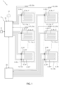
- Platform 1 comprises a plurality of self-regulating electrical circuits 2 and a control system 3.
- each circuit 2 is a radiant floor heating circuit.
- circuit 2 is formed by a PTC ("Positive Temperature Coefficient") semiconductor cable, which is self-regulating and self-modulating, i.e. having a conductive matrix with a resistivity that increases with temperature, such that current absorption decreases as the temperature increases until an equilibrium temperature is reached at which the current absorption reaches its minimum value.
- PTC Physical Temperature Coefficient
- circuit 2 With each activation of circuit 2, i.e. when circuit 2 is electrically powered, the electrical absorption of circuit 2 has an initial peak value which rapidly decreases over time. Fluctuations in the peak value depend on the starting temperature and the time during which circuit 2 has not been electrically powered.
- platform 1 comprises a plurality of first areas 11.
- Each first area 11 comprises at least two circuits 2.
- Control system 3 is configured to sequentially activate a circuit 2 of each first area 11 and subsequently to sequentially activate another circuit 2 of each first area 11.
- each first area 11 is a panelled area, i.e. it comprises at least one panel, which can be heated by the respective circuits 2.
- circuits 2 of the first area 11 have substantially equal power absorption to each other, and preferably substantially equal length to each other.
- circuits 2 of first areas 11 are substantially the same as each other.
- first areas 11 have an equal number of circuits 2 to each other. Therefore, first areas 11 have a total power absorption, i.e. the power absorption when all their circuits 2 are active, which is substantially equal to each other.
- platform 1 comprises a second area 12.
- Second area 12 comprises at least two circuits 2. Each circuit 2 of second area 12 has a lower power absorption than circuits 2 of first areas 11.
- Control system 3 is configured to sequentially activate circuits 2 of second area 12 after having activated circuits 2 of first areas 11.
- second area 12 is a panelled area, i.e. it comprises at least one panel, which can be heated by the respective circuits 2.
- circuits 2 of second area 12 have substantially equal power absorption to each other, and preferably substantially equal length to each other.
- circuits 2 of second area 12 are substantially the same as each other.
- the number of circuits 2 of second area 12 is greater than the number of circuits 2 of each first area 11.
- second area 12 has a total power absorption, i.e. the power absorption when all its circuits 2 are active, substantially equal to the total power absorption of each first area 11.
- the length of each circuit 2 of second area 12 is less than the length of each circuit 2 of each first area 11.
- platform 1 comprises at least a first temperature sensor 21 configured to produce a first signal indicative of a first temperature of platform 1.
- Control system 3 is configured to receive the first signal from first sensor 21 and to sequentially activate circuits 2 on the basis of the first signal.
- platform 1 comprises a plurality of thermal zones Z.
- Each thermal zone Z comprises a respective first sensor 21 and a plurality of first areas 11.
- first sensor 21 is a floor temperature sensor configured to detect the temperature of the respective thermal zone Z wherein it is inserted. Therefore, each thermal zone Z is associated with the respective first signal, produced by the respective first sensor 21 and indicative of the respective first temperature.
- each thermal zone Z comprises a respective second area 12, i.e. the number of second areas 12 is equal to the number of thermal zones Z.
- control system 3 comprises a main control unit 3a configured to directly control a first thermal zone Za of the plurality of thermal zones, and a respective auxiliary control unit 3b for each further thermal zone Zb in addition to first thermal zone Za.
- Each auxiliary control unit 3b is connected to the respective thermal zone Zb and main control unit 3a, and main control unit 3a is configured to control each further thermal zone Zb via the respective auxiliary control unit 3b.
- platform 1 comprises at least a second temperature sensor 22 configured to produce a second signal indicative of a second temperature of an environment associated with platform 1.
- Control system 3 is configured to receive the second signal from second sensor 22 and to sequentially activate circuits 2 on the basis of the second signal.
- each thermal zone Z comprises a respective second sensor 22, which is a room temperature sensor configured to detect the temperature of the environment associated with the respective thermal zone Z.
- the first temperature relates to thermal zone Z and the second temperature relates to the environment associated with thermal zone Z.
- main control unit 3a is configured to receive signals to start or stop platform 1 from an electronic device 31 connected to main control unit 3a via cable or wirelessly.
- electronic device 31 is a smartphone or tablet provided with an application for remote control of platform 1, a manual control panel or an interface with a thermal building management system (BMS).
- BMS thermal building management system
- Main control unit 3a is further configured to receive signals from an external multimeter 41 configured to detect an instantaneous power absorbed by platform 1, i.e. the instantaneous power absorbed by all circuits 2 of platform 1.
- Platform 1 comprises two thermal zones Z, namely first thermal zone Za and further thermal zone Zb.
- Each thermal zone Za, Zb comprises a respective first sensor 21a, 21b and a respective second sensor 22a, 22b.
- Control system 3 comprises main control unit 3a, configured to directly control first thermal zone Za, and auxiliary control unit 3b for further thermal zone Zb.
- Auxiliary control unit 3b is connected to further thermal zone Zb and main control unit 3a, and main control unit 3a is configured to control further thermal zone Zb via auxiliary control unit 3b.
- First thermal zone Za comprises n a first areas 11a_1, 11a_2, ..., 11a_ n a , arranged aligned with one other in this order
- further thermal zone Zb comprises n b first areas 11b_1, 11b_2, ..., 11b_ n b , arranged aligned with one other in this order and parallel to the n a first areas of first thermal zone Za.
- n a is greater than or equal to two and n b is greater than or equal to two.
- n a is equal to n b i.e. first thermal zone Za and further thermal zone Zb have the same number of first areas 11.
- Each first area 11 has two circuits 2, which have substantially equal power absorption and substantially equal length to each other.
- the two circuits 2 of each first area 11 are arranged in a serpentine pattern with parallel straight sections and curved end sections, wherein each end section is configured to connect two consecutive straight sections of the respective circuit 2.
- First thermal zone Za comprises a respective second area 12a and further thermal zone Zb comprises a respective second area 12b.
- Each second area 12 has four circuits 2, which have substantially equal power absorption and substantially equal length to one another.
- the power absorption of each circuit 2 of second area 12 is substantially half the power absorption of each circuit 2 of each first area 11, and the length of each circuit 2 of second area 12 is substantially half the length of each circuit 2 of each first area 11.
- the two circuits 2 of each portion of each second area 12 are arranged in a serpentine pattern with parallel straight sections and curved end sections, wherein each end section is configured to connect two consecutive straight sections of the respective circuit 2.
- main control unit 3a is configured to:
- main control unit 3a is configured to:
- the present invention further relates to a method for controlling a radiant platform 1 comprising a plurality of self-regulating electrical circuits 2, wherein said plurality comprises at least a first circuit and a second circuit.
- the method comprises the step of activating circuits 2 sequentially, wherein the second circuit is activatable consecutively to the first circuit and the activation of the second circuit is subject to a verification of exceeding a limit power P_lim.
- the first circuit and the second circuit belong to the same thermal zone Z and are activatable consecutively, i.e. there is no third circuit of such thermal zone Z which is activatable between the first circuit and the second circuit.
- the verification of exceeding the limit power P_lim comprises a first verification step, wherein it is verified that an estimated absorbed power does not exceed the limit power P_lim, and a second verification step, wherein it is verified that an actual absorbed power does not exceed the limit power P_lim.
- the first verification step is theoretical as the limit power P_lim is compared with an estimated absorbed power
- the second verification step is practical as the limit power P_lim is compared with an actual absorbed power.
- the estimated absorbed power comprises the estimated power absorbed by the second circuit, which is calculated on the basis of the power actually absorbed by the first circuit, while the actual absorbed power comprises the power actually absorbed by the second circuit.
- the first verification step occurs before the activation of the second circuit, while the second verification step occurs after the activation of the second circuit.
- the first verification step comprises the steps of:
- the instantaneous power absorbed P_ass is the sum of the power absorbed by all circuits 2 of platform 1 that are active.
- the method comprises the steps of:
- the first predetermined time interval ⁇ t 1 between two consecutive iterations allows the instantaneous absorbed power P_ass (and thus the estimated absorbed power) to decrease as circuits 2 are formed by PTC semiconductor cables.
- the first predetermined time interval ⁇ t 1 has a duration of five seconds, and the first predetermined number of iterations is twelve.
- the method comprises a step of generating a pre-alarm if the first condition is not met after the first predetermined number of iterations.
- Such pre-alarm is generated immediately before activating the second circuit.
- the pre-alarm is a signalling that does not interrupt the method, i.e. it does not prevent the activation of the second circuit.
- the second verification step comprises the steps of:
- the step of detecting the actual absorbed power P_ass is executed after a second predetermined time interval ⁇ t 2 from the activation of the second circuit.
- the second predetermined time interval ⁇ t 2 has a duration of one second.
- the method comprises a routine if the second condition is not met, wherein the routine comprises the steps of:
- the third predetermined time interval ⁇ t 3 waits for the third predetermined time interval ⁇ t 3 between the deactivation and activation of the second circuit allows the decrease of the actual absorbed power P_ass as circuits 2 are formed by PTC semiconductor cables.
- the third predetermined time interval ⁇ t 3 has a duration of five seconds.
- the method comprises the steps of:
- the alarm is a signalling that interrupts the method, i.e. prevents the activation of the second circuit, and requires manual intervention.
- the second predetermined number of iterations is twelve.
- the limit power P_lim is defined in such a way that at least one circuit 2 of platform 1 is activated.
- the limit power P_lim is such that, when only one circuit 2 of platform 1 is active, the power absorbed by such circuit 2, detected after the second predetermined time interval ⁇ t 2 for the above reasons, is not greater than the limit power P_lim.
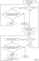
- the method is exemplified in the flow chart of Figure 2 , wherein the first circuit is referred to as the circuit i and the second circuit is referred to as the circuit i + 1.
- circuit i and the circuit i + 1 belong:
- circuit i is active and power P_max i , i.e. the maximum power absorbed by circuit i , is stored.
- the instantaneous power absorbed P_ass by the plurality of circuits 2 is determined, the estimated absorbed power P_ass + P_max i is obtained, and the first condition P_ass + P_max i ⁇ P_lim is verified.
- circuit i + 1 is activated and P_max i +1 , i.e. the maximum power absorbed by circuit i + 1, is stored.
- the first verification step is performed iteratively, wherein two consecutive iterations are spaced temporally by the first predetermined time interval ⁇ t 1 .
- the circuit i + 1 is activated and P_max i +1 . i.e. the maximum power absorbed by the circuit i + 1, is stored. If the first condition is not met after the first predetermined number of iterations, the pre-alarm is generated immediately before activating the circuit i+1.
- the second predetermined time interval ⁇ t 2 is waited and then the second verification step is executed.
- the power absorbed by the plurality of circuits 2 after activating the circuit i + 1 is detected, obtaining the actual absorbed power P_ass, and the second condition P_ass ⁇ P_lim is verified.
- circuit i which is now circuit i + 1
- power P_max ⁇ which is now power P_max i +1
- circuit i + 1 is kept active and the method is iterated. This is equivalent to stating that circuit i + 1 (i.e. the second circuit) in one iteration of the method is circuit i (i.e. the first circuit) in the subsequent iteration of the method.
- the routine is executed iteratively if the second condition P_ass ⁇ P_lim is not met. If the second predetermined number of iterations is reached, the alarm is generated, i.e. the alarm is generated if the second conditionand P_ass ⁇ P_lim is not met after the second predetermined number of iterations of the routine.
- circuit i belongs to the (last) first area 11 and circuit i + 1 belongs to the second area 12 of the same thermal zone Z, e.g. circuit i is circuit 2a_ n a ' of first area 11a_ n a and circuit i + 1 is circuit 2a' of second area 12a.
- the estimated absorbed power is P_ass + P_max i / 2 and thus the first condition is P_ass + P_max i / 2 ⁇ P_lim, as the power absorption of circuit i + 1 (which belongs to second area 12) is substantially half of the power absorption of circuit i (which belongs to first area 11).
- control system 3 In use, the method is implemented by control system 3.
- control system 3 starts the method as main control unit 3a receives signals from electronic device 31, or automatically, e.g. in a time-controlled manner (preferably on the basis of the time slot).
- Control system 3 can control platform 1 in different ways, depending on the presence and possible use of first sensor 21 and second sensor 22.
- control system 3 can activate circuits 2 sequentially, according to the described method, until the limit power P_lim is reached. In such a case, neither first sensor 21 nor second sensor 22 are required.
- main control unit 3a can sequentially activate circuits 2 of first thermal zone Za, and each auxiliary control unit 3b can sequentially activate circuits 2 of the respective thermal zone Zb.
- main control unit 3a receives signals from multimeter 41 and each auxiliary control unit 3b, which in turn receives signals from main control unit 3a.
- control system 3 can activate circuits 2 as a function of jointly the power limit P_lim, as described above, and the temperature, as described in detail hereinafter.
- control system 3 can sequentially activate circuits 2, according to the described method, until a desired temperature of the respective thermal zone Z is reached.
- the first signal of each first sensor 21 is indicative of the respective first temperature relative to the respective thermal zone Z
- the first signal can be compared with a respective first reference signal, indicative of the desired temperature of the respective thermal zone Z, and circuits 2 of the respective thermal zone Z can be activated until the first signal and the respective first reference signal are substantially equal, i.e. the respective thermal zone Z has substantially reached the desired temperature.
- circuits 2 of thermal zone Z are sequentially deactivated, e.g. in the same order as they were activated, until the first signal and the respective first reference signal are substantially equal.
- control system 3 can sequentially activate circuits 2, according to the described method, until a desired temperature of the environment associated with platform 1 is reached.
- control system 3 can sequentially activate circuits 2, according to the described method, until a desired temperature of the environment associated with the respective thermal zone Z is reached.
- the second signal of each second sensor 22 is indicative of the respective second temperature relative to the environment associated with the respective thermal zone Z
- the second signal can be compared with a respective second reference signal, indicative of the desired temperature of the environment associated with the respective thermal zone Z, and circuits 2 of the respective thermal zone Z can be activated until the second signal and the respective second reference signal are substantially equal, i.e. the environment associated with the respective thermal zone Z has substantially reached the desired temperature.
- circuits 2 of thermal zone Z are sequentially deactivated, e.g. in the same order as they were activated, until the second signal and the respective second reference signal are substantially equal.
- the number of elements of platform 1 of the illustrated embodiment can be generalised.
- the power absorption of each circuit 2 of second area 12 is substantially n / m times the power absorption of each circuit 2 of each first area 11, and preferably the length of each circuit 2 of second area 12 is substantially n / m times the length of each circuit 2 of each first area 11.
- the number of further thermal zones Zb (and thus the number of auxiliary control units 3b) is k - 1
- the number of first sensors 21 is k
- the number of second sensors 22 is preferably k .
- the sequential activation of circuits 2, subject to verification that the limit power has been exceeded allows efficient control of platform 1.
- the activation of circuit 2 is temporally spaced out.
- the exceeding of the limit power is verified both before and after the activation of each circuit 2 via a theoretical and practical verification, respectively.
- the method can be applied iteratively, for each pair of circuits 2 that are activatable consecutively.
- Platform 1 with its plurality of first areas 11 allows a modular approach, both structurally and functionally. Indeed, first areas 11 can be arranged aligned and circuits 2 of first areas 11 are activated sequentially, improving thermal homogeneity. Furthermore, circuits 2 of second areas 12 allow fine tuning, as they have a lower power absorption than circuits 2 of first areas 11 and are activated after them.
- Platform 1 with the plurality of thermal zones Z allows to further improve the control, as each thermal zone Z is associated with the respective first temperature, detected by the respective first sensor 21, which can be used to implement closed-loop control on the basis of the temperature of the respective thermal zone Z.
- each further thermal zone Zb in addition to first thermal zone Za is controlled by the respective auxiliary control unit 3b, which in turn is controlled by main control unit 3a which receives signals from multimeter 41 and thus knows the instantaneous power absorbed by all circuits 2 of platform 1.
- the temperature of the environment associated with each thermal zone Z, detected via the respective second sensor 22, can be used to implement closed-loop control on the basis of the temperature of the environment associated with the respective thermal zone Z.
Landscapes
- Control Of Electrical Variables (AREA)
- Control Of Temperature (AREA)
Applications Claiming Priority (1)
| Application Number | Priority Date | Filing Date | Title |
|---|---|---|---|
| IT102023000019827A IT202300019827A1 (it) | 2023-09-26 | 2023-09-26 | Metodo per controllare una pedana radiante e relativa pedana radiante |
Publications (1)
| Publication Number | Publication Date |
|---|---|
| EP4531495A1 true EP4531495A1 (fr) | 2025-04-02 |
Family
ID=89158250
Family Applications (1)
| Application Number | Title | Priority Date | Filing Date |
|---|---|---|---|
| EP24202111.1A Pending EP4531495A1 (fr) | 2023-09-26 | 2024-09-24 | Méthode de contrôle d'un plancher radiant et plancher radiant |
Country Status (2)
| Country | Link |
|---|---|
| EP (1) | EP4531495A1 (fr) |
| IT (1) | IT202300019827A1 (fr) |
Citations (4)
| Publication number | Priority date | Publication date | Assignee | Title |
|---|---|---|---|---|
| DE202006007730U1 (de) * | 2006-05-12 | 2006-08-17 | Moletherm Holding Ag | Stromversorgungseinheit zur Stromversorgung einer elektrischen Flächenheizung, insbesondere für eine Gebäudewand |
| US20060242900A1 (en) * | 2005-01-05 | 2006-11-02 | Lovelace Reginald B | Nematode extermination in place using heat blankets |
| EP3070569A2 (fr) * | 2015-03-20 | 2016-09-21 | Andrea Zeziola | Système de gestion intelligente pour centrale de chauffage avec éléments radiatifs à électricité |
| CN106931500B (zh) * | 2017-04-06 | 2020-02-04 | 北京创新爱尚家科技股份有限公司 | 石墨烯地暖控制方法及系统 |
-
2023
- 2023-09-26 IT IT102023000019827A patent/IT202300019827A1/it unknown
-
2024
- 2024-09-24 EP EP24202111.1A patent/EP4531495A1/fr active Pending
Patent Citations (4)
| Publication number | Priority date | Publication date | Assignee | Title |
|---|---|---|---|---|
| US20060242900A1 (en) * | 2005-01-05 | 2006-11-02 | Lovelace Reginald B | Nematode extermination in place using heat blankets |
| DE202006007730U1 (de) * | 2006-05-12 | 2006-08-17 | Moletherm Holding Ag | Stromversorgungseinheit zur Stromversorgung einer elektrischen Flächenheizung, insbesondere für eine Gebäudewand |
| EP3070569A2 (fr) * | 2015-03-20 | 2016-09-21 | Andrea Zeziola | Système de gestion intelligente pour centrale de chauffage avec éléments radiatifs à électricité |
| CN106931500B (zh) * | 2017-04-06 | 2020-02-04 | 北京创新爱尚家科技股份有限公司 | 石墨烯地暖控制方法及系统 |
Also Published As
| Publication number | Publication date |
|---|---|
| IT202300019827A1 (it) | 2025-03-26 |
Similar Documents
| Publication | Publication Date | Title |
|---|---|---|
| US9652010B2 (en) | System and method for sequential application of power to electrical loads | |
| EP4531495A1 (fr) | Méthode de contrôle d'un plancher radiant et plancher radiant | |
| DE102015005945B3 (de) | Bodenelement für ein Flugzeug, Verfahren zum Betreiben eines Bodenelements für ein Flugzeug, Heizsystem für ein Flugzeug und Verfahren zum Herstellen eines Bodenelements für ein Flugzeug | |
| JP2013238351A (ja) | 空調制御装置、温度センサの劣化判定方法及びプログラム | |
| CN101868673A (zh) | 一种用于控制烹饪器具、特别是电磁炉的方法和装置 | |
| CN104918361B (zh) | 无线灯光控制系统中控制器与执行器之间的扫描识别方法 | |
| CN109785546B (zh) | 火灾逃生指示的方法、装置和存储介质 | |
| US20100201384A1 (en) | Structural Health Monitoring System/Method Using Electroactive Polymer Fibers | |
| CN115818404A (zh) | 一种室外扶梯自动加热方法 | |
| KR20090100856A (ko) | 분할난방 시스템 | |
| CN108476577B (zh) | 需求响应照明控制系统和方法 | |
| JP2012147628A (ja) | 電力制御システム及び電力制御装置 | |
| CN103383586B (zh) | 控制功率馈送的方法及装置 | |
| CN104633946A (zh) | 热泵热水器的启动方法 | |
| JP6767314B2 (ja) | レーザ制御装置 | |
| KR20090058479A (ko) | 무자계 온도 조절기 | |
| EP3070569B1 (fr) | Procede de gestion intelligente pour centrale de chauffage avec elements radiatifs a electricite | |
| CN210381319U (zh) | 面状电热装置的整面防过热保护系统及一种加热设备 | |
| KR102430619B1 (ko) | 데이터 관리 방법 | |
| DE102017215415A1 (de) | Überlasterkennung mit dynamischer Steigungsanpassung | |
| JP4973581B2 (ja) | 電動車両の昇圧コンバータ制御装置 | |
| KR102773441B1 (ko) | 열선 타일 | |
| CN108683492B (zh) | 一种可信无线传感器及控制方法 | |
| US20260067998A1 (en) | Multi-layred electric heating tile | |
| CN112229045A (zh) | 一种矩阵切换系统的智能温度控制方法、装置和系统 |
Legal Events
| Date | Code | Title | Description |
|---|---|---|---|
| PUAI | Public reference made under article 153(3) epc to a published international application that has entered the european phase |
Free format text: ORIGINAL CODE: 0009012 |
|
| STAA | Information on the status of an ep patent application or granted ep patent |
Free format text: STATUS: THE APPLICATION HAS BEEN PUBLISHED |
|
| AK | Designated contracting states |
Kind code of ref document: A1 Designated state(s): AL AT BE BG CH CY CZ DE DK EE ES FI FR GB GR HR HU IE IS IT LI LT LU LV MC ME MK MT NL NO PL PT RO RS SE SI SK SM TR |
|
| STAA | Information on the status of an ep patent application or granted ep patent |
Free format text: STATUS: REQUEST FOR EXAMINATION WAS MADE |
|
| 17P | Request for examination filed |
Effective date: 20250430 |