EP4533983A2 - Récipient à boire présentant une enveloppe et sac à mains et dispositif de maintien pour récipient à boire - Google Patents
Récipient à boire présentant une enveloppe et sac à mains et dispositif de maintien pour récipient à boire Download PDFInfo
- Publication number
- EP4533983A2 EP4533983A2 EP25159245.7A EP25159245A EP4533983A2 EP 4533983 A2 EP4533983 A2 EP 4533983A2 EP 25159245 A EP25159245 A EP 25159245A EP 4533983 A2 EP4533983 A2 EP 4533983A2
- Authority
- EP
- European Patent Office
- Prior art keywords
- container
- holding structure
- drinking
- section
- drinking vessel
- Prior art date
- Legal status (The legal status is an assumption and is not a legal conclusion. Google has not performed a legal analysis and makes no representation as to the accuracy of the status listed.)
- Pending
Links
Images










Classifications
-
- A—HUMAN NECESSITIES
- A45—HAND OR TRAVELLING ARTICLES
- A45F—TRAVELLING OR CAMP EQUIPMENT: SACKS OR PACKS CARRIED ON THE BODY
- A45F3/00—Travelling or camp articles; Sacks or packs carried on the body
- A45F3/16—Water-bottles; Mess-tins; Cups
- A45F3/18—Water-bottles; Mess-tins; Cups of rigid material
-
- A—HUMAN NECESSITIES
- A45—HAND OR TRAVELLING ARTICLES
- A45C—PURSES; LUGGAGE; HAND CARRIED BAGS
- A45C11/00—Receptacles for purposes not provided for in groups A45C1/00-A45C9/00
- A45C11/20—Lunch or picnic boxes or the like
-
- A—HUMAN NECESSITIES
- A45—HAND OR TRAVELLING ARTICLES
- A45C—PURSES; LUGGAGE; HAND CARRIED BAGS
- A45C13/00—Details; Accessories
- A45C13/02—Interior fittings; Means, e.g. inserts, for holding and packing articles
-
- A—HUMAN NECESSITIES
- A45—HAND OR TRAVELLING ARTICLES
- A45C—PURSES; LUGGAGE; HAND CARRIED BAGS
- A45C15/00—Purses, bags, luggage or other receptacles covered by groups A45C1/00 - A45C11/00, combined with other objects or articles
-
- A—HUMAN NECESSITIES
- A47—FURNITURE; DOMESTIC ARTICLES OR APPLIANCES; COFFEE MILLS; SPICE MILLS; SUCTION CLEANERS IN GENERAL
- A47G—HOUSEHOLD OR TABLE EQUIPMENT
- A47G19/00—Table service
- A47G19/22—Drinking vessels or saucers used for table service
-
- A—HUMAN NECESSITIES
- A47—FURNITURE; DOMESTIC ARTICLES OR APPLIANCES; COFFEE MILLS; SPICE MILLS; SUCTION CLEANERS IN GENERAL
- A47G—HOUSEHOLD OR TABLE EQUIPMENT
- A47G19/00—Table service
- A47G19/22—Drinking vessels or saucers used for table service
- A47G19/2288—Drinking vessels or saucers used for table service with means for keeping liquid cool or hot
-
- A—HUMAN NECESSITIES
- A45—HAND OR TRAVELLING ARTICLES
- A45C—PURSES; LUGGAGE; HAND CARRIED BAGS
- A45C2200/00—Details not otherwise provided for in A45C
- A45C2200/20—Carrying beverage vessels, e.g. bottles
-
- A—HUMAN NECESSITIES
- A45—HAND OR TRAVELLING ARTICLES
- A45F—TRAVELLING OR CAMP EQUIPMENT: SACKS OR PACKS CARRIED ON THE BODY
- A45F5/00—Holders or carriers for hand articles; Holders or carriers for use while travelling or camping
- A45F5/1583—Holders or carriers for beverage vessels, e.g. bottles
-
- A—HUMAN NECESSITIES
- A47—FURNITURE; DOMESTIC ARTICLES OR APPLIANCES; COFFEE MILLS; SPICE MILLS; SUCTION CLEANERS IN GENERAL
- A47G—HOUSEHOLD OR TABLE EQUIPMENT
- A47G23/00—Other table equipment
- A47G23/02—Glass or bottle holders
- A47G2023/0275—Glass or bottle holders with means for keeping food cool or hot
- A47G2023/0283—Glass or bottle holders with means for keeping food cool or hot for one glass or cup
- A47G2023/0291—Glass or bottle holders with means for keeping food cool or hot for one glass or cup flexible sleeves or jackets
Definitions
- the invention relates to a drinking vessel comprising a container for a beverage and a cover, as well as a holding structure that releasably receives the container, wherein the cover at least partially covers the holding structure on a side facing away from the container. Furthermore, the invention relates to a handbag with a drinking vessel and a holding device for the drinking vessel.
- a container assembly for cooling wine bottles is known.
- the container assembly has a receptacle for wine bottles into which a water-ice mixture can be introduced, which cools a wine bottle arranged in the receptacle.
- the US 2008/0087786 A1 describes a drinking vessel comprising a beverage can housed in a cup-shaped support structure.
- the drinking vessel has a bag that partially surrounds the support structure to thermally insulate the beverage can.
- thermos flask is known with a container that is detachably received in a circumferentially closed support structure that surrounds the container. An insulating space is located between the support structure and the container.
- a handbag with a holder for a drinking vessel in the shape of a beverage can is specified.
- This holder is attached to a wall of the handbag and can be made of a thermally insulating material so that a beverage held in the drinking vessel maintains its temperature.
- Drinking vessels with a coating which are used for holding drinks, are for example from the CN 105 640 222 A Women, in particular, use portable drinking vessels that allow them to enjoy a drink at any time, for example, on the way to work, while driving or using public transport, or while shopping. Such portable drinking containers are often carried in handbags.
- the DE 20 2004 004 193 U1 Describes a cover made of neoprene material for a drinking vessel, which can in particular be designed as a cup.
- the cover can be removed from the drinking vessel and serves to insulate it in order to slow down heat loss from a beverage in the drinking vessel or heat input into a beverage in the drinking vessel.
- the DE 20 2004 014 541 U1 discloses a drinking vessel comprising a container for holding a beverage and a cover made of textile and leather material, which has a connecting section with buttons, buckles, hook-and-loop fasteners, or zippers.
- the cover can be removed from the container for cleaning the container of the drinking vessel.
- the cover has buttons, buckles, hook-and-loop fasteners, and/or zippers that can be opened to detach it from the container. Due to the mechanical stress caused by opening and closing zippers, buttons, buckles, and hook-and-loop fasteners, the cover is subject to wear when removed and reattached to the container of the drinking vessel.
- a drinking vessel with a container which has a holding structure that accommodates the container.
- the container is cup-shaped and has a container base wall and a side wall connected to the container base wall.
- the holding structure is designed as a hollow body with a cavity and a cavity wall surrounding the side wall of the container, with an insulating space formed between the side wall of the container and the hollow body.
- the object of the invention is to provide a drinking vessel with a container for a beverage which is easy to clean while providing good thermal insulation of the beverage, wherein the drinking vessel can be adapted to the appearance of a handbag or other objects or to an interior.
- Drinking beverages regularly and in sufficient quantities is beneficial to health if, on the one hand, the beverages are tailored to the needs of the human body and, on the other hand, hygiene regulations are observed. For hygiene reasons, the areas of a drinking vessel that are touched by the mouth and that come into contact with a beverage contained therein must be cleaned regularly.
- a drinking vessel that is tailored by means of a covering to the appearance of a handbag, a tennis bag, a golf bag or a travel bag, but also to the interior or seats of a motor vehicle or aircraft, for example by the material, color and surface texture of the covering matching the material, color and surface texture of the bag, the interior or the seats, will be popular with women in particular, not only for health reasons but also for fashion reasons.
- the invention proposes to hold the beverage in the drinking vessel in a container which is held in a holding structure which carries the coating, wherein the coating covers the holding structure at least partially on a side facing away from the container and wherein the container is detachably secured to the holding structure.
- the container to be cleaned in a dishwasher without damaging the coating.
- the coating of the drinking vessel can be removed from the container without subjecting the coating to undesirable mechanical stress. Furthermore, this ensures that the container maintains a fundamentally consistent position relative to the holding structure, regardless of the drinking vessel's spatial orientation.
- the container is cup-shaped. It has a container base wall and a side wall connected to the container base wall.
- the support structure comprises a hollow body with a cavity in which the container can be arranged, wherein the hollow body has a hollow body wall surrounding the side wall of the container.
- the holding structure has a stable shape but can be elastic.
- the holding structure can have a support section that serves to support the container in a bottom section. It is advantageous if the holding structure has a hollow body wall on which, on a side facing the side wall of the container, support bodies with support sections are formed for contact with the side wall of the container. This ensures that the container is securely held in the holding structure.
- the support sections of the hollow body wall can in particular be rib-shaped.
- the support bodies can have a holding contour designed to engage over a side wall section of the side wall in a holding section of the container, which serves to press the container in the holding structure against the support section with a clamping force when the holding contour engages over the side wall section. This measure serves to releasably secure the container in the holding structure and ensures a firm fit of the container in the cavity of the hollow body of the holding structure.
- the holding structure can have a
- the container can have an opening in the bottom of the container.
- the container can have a mounting structure on its bottom-side container section that protrudes through the bottom-side opening.
- a preferred embodiment of the drinking vessel provides that the mounting structure protruding through the bottom-side opening of the hollow body has a dovetail-shaped cross-section with an undercut.
- the hollow body can then have elastically deformable tongues that protrude into the undercut of the container structure. In this way, the container can be releasably secured in the holding structure with a secure fit.
- the container can also have an external thread that can be screwed into an internal thread of the hollow body to secure the container in the hollow body.
- the container can also be held in the hollow body by means of a magnetic element fixed in the hollow body and thus releasably secured to the holding structure.
- magnetizable material can be arranged in the container bottom wall and a magnetic element can be integrated into the holding structure in a section opposite the container bottom wall.
- a drinking vessel according to the invention preferably has a drinking body that is positively connected to the hollow body or that rests positively on the coating and is connected to the container.
- the drinking body has a concave recess into which a beverage held in the container can be fed from the container through a container opening opposite the container base. It is advantageous if the drinking body is connected to the container in a fluid-tight manner. This prevents liquid from escaping from the container if the drinking vessel is tipped over.
- a preferred embodiment of the drinking vessel provides that the drinking body has a drinking body opening connecting the interior of the container with the concave recess of the drinking body and has an adjustable lid body for selectively opening and closing the drinking body opening. Between the lid body and the drinking body, a Drinking body sealing element is provided for sealing the lid body to the drinking body.
- the drinking body engages over an opening-side container section with a container connection section and has a ring section with an annular flange-shaped contact surface which, when the drinking body is connected to the container received in the holding structure, faces an opening edge of the cavity of the holding structure. In this way, it is possible to protect the coating at the transition between the holding structure and the drinking body from mechanical damage.
- the drinking body and the holding structure defining an annular, air-filled insulation space coaxial with the container opening, which separates the holding structure from the container connection section of the drinking body, it is possible to ensure that only a small amount of heat is introduced from the drinking body into the holding structure when drinking a hot beverage.
- the drinking vessel has a cover element that is detachably connected to a base section of the support structure and overlaps the cover.
- the support structure is made of an elastically deformable material whose modulus of elasticity is greater than the modulus of elasticity of the container material.
- the support structure can be made, in particular, of a plastic material.
- the container can be made of a metallic material, in particular stainless steel.
- the cover can be made of a flexible material, in particular leather.
- the invention also extends to a bag, e.g., a handbag, a tennis bag, or a travel bag with a drinking vessel, which is at least partially made of the flexible material.
- a bag e.g., a handbag, a tennis bag, or a travel bag with a drinking vessel, which is at least partially made of the flexible material.
- the handbag can have a bag body with a holding device for the drinking vessel arranged in the bag body.
- the invention also extends to a holding device for a drinking vessel, which preferably has the features specified above.
- the holding device has a sleeve body with a receptacle adapted to the holding structure of the container, in which the drinking vessel can be held.
- the holding device has at least one connecting means. In this way, the drinking vessel can be carried in the bag without tipping over.
- the connecting means can, in particular, be designed as a strap that can be connected to a carrying strap of the bag to hold the holding device in the pocket body. This measure allows the holding device to be secured in a wide variety of pockets.
- the strap has a strap lock with a first lock part and a second lock part complementary to the first lock part, which serves to open and close a strap loop that can be placed around the carrying strap of the bag to hold the holding device in the bag body. This allows the holding device to be quickly secured in a bag and quickly released from a bag.
- attachment points can be provided for securing the holder to the body of the bag. This ensures a secure fit for the holder for a drinking vessel in a bag.
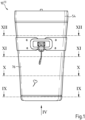
- the first drinking vessel 10 (1) shown is detachable and has an appearance that matches the design of a handbag.
- Fig. 2 is an exploded view of the drinking vessel 10 (1) .
- the drinking vessel 10 (1) comprises a container 12 made of stainless steel, designed as a cup, which has a container bottom wall 14 and a side wall 16 connected to the container bottom wall 14.
- a holding structure 18 in the form of a hollow body made of an elastic plastic material in the drinking vessel 10 (1) .
- the holding structure 18 has a stable shape and serves as a receptacle for the container 12.
- the Fig. 3 is a perspective view of the drinking vessel 10 (1) .
- Fig. 4 is a plan view of the drinking vessel in the direction of arrow IV from Fig. 1 to see.
- the Fig. 5 shows a section of the drinking vessel along the line V - V from Fig. 4 .
- the Fig. 6 is an enlarged view of Section VI from Fig. 5 .
- the hollow body of the support structure 18 has a cavity wall 20 that surrounds the side wall 16 of the container 12.
- the hollow body of the support structure 18 has a support section 22 that serves to support the container 12 in a bottom-side container section 24.
- the container 12 has an interior space 26 open on one side, which, starting from the container bottom 28 in the bottom-side container section 24, leads to a Container opening 30, which has a circular opening edge 31.
- the container 12 has a container axis 32 perpendicular to the container opening 30, passing through the center of the container opening 30, which is an axis of symmetry of the interior 26.
- the Fig. 5 is a longitudinal section of the drinking vessel in a plane in which the container axis 32 runs.
- the container 12 has a container bottom wall 14 with an annular section 34, to which a container section 36 with a mounting structure is connected.
- the container section 36 with the mounting structure has, in the plane of a longitudinal section in which the container axis 32 runs, a dovetail-shaped cross-section with an outer contour that has an undercut. In the bottom-side container section 24, this outer contour partially follows the shape of a mushroom head.
- the mounting structure in the container section 36 protrudes through a container-bottom-side opening 38 of the hollow body of the holding structure 18.
- the container-bottom-side opening 38 of the hollow body of the support structure 18 is delimited by elastic tongues 40, each having a circular-arc-shaped edge portion 42 facing the container axis 32, which rests against the container bottom wall 14 of the container 12 in the region of the undercut of the mounting structure in the container portion 36. Between the tongues 40 and the annular portion 34 of the container bottom wall 14, there is an annular air space 35 that isolates the container bottom wall 14 from the support structure 18.
- the surface area of the cross-section of the interior 26 of the container 12 perpendicular to the container axis 32 and the surface area of the cross-section of the container 12 perpendicular to the container axis 32 increase in a receiving section 44 of the container 12 for receiving a beverage up to a maximum value.
- the container 12 has an opening-side container section 46 connected to the receiving section 44 with the container opening 30, in which the maximum diameter of the interior 26 of the container 12 and the maximum diameter of the cross-section of the container 12 perpendicular to the container axis 32 is tapered compared to the maximum diameter of the interior 26 of the container 12 and the maximum diameter of the cross-section of the container 12 in the opening-side container section 46.
- the Fig. 7 is an enlarged view of Section VII from Fig. 5 .
- the shell 48 of the container 12 is concavely curved.
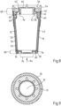
- the Fig. 8 is another longitudinal section of the drinking vessel 10 (1) in one of the lines VIII - VIII from Fig. 4 corresponding cutting plane.
- the Fig. 9 shows a cross section of the drinking vessel in one of the lines IX - IX from Fig. 1 corresponding cutting plane.
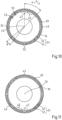
- the Fig. 11 and the Fig. 12 are the lines X - X, XI - XI and XII - XII from Fig. 1 corresponding cross sections of the drinking vessel 10 can be seen.
- the inner and outer edges of the cross-section of the wall of the container 12 are circular, as shown in the Fig. 9
- its side wall 16 has a cross-sectional plane perpendicular to the container axis 32, as shown in Fig. 10
- the Fig. 11 and the Fig. 12 show alternating first wall sections 45, which are curved in an arcuate manner, and second wall sections 47, which are straight.
- the container 12 has a rotational symmetry with respect to the container axis 32.
- the side wall 16 of the container 12 opposite the cavity wall 20 of the holding structure 18 has in the receiving section 44, as shown in the Fig. 10 , the Fig. 11 and the Fig. 12 can be seen, a circular cross-section.
- the inner circle and the outer circle of this circular cross-section lie here on a cone that is open in the direction of the container axis 32 pointing towards the container opening 30.
- rib-shaped support bodies 52 are arranged on the cavity wall 20 of the holding structure 18, regularly distributed over its inner circumference and grouped into support body pairs 51.
- Each of these support bodies has support sections 53 designed as support surfaces and extends in a longitudinal direction along a rib axis 55 that defines a plane with the direction of the container axis 32.
- the azimuthal distance ⁇ of the support bodies 52 of a support body pair 51, relative to the container axis 32, is smaller than the azimuthal distance ⁇ between adjacent support bodies 52 from different support body pairs 51.
- the shell 48 of the container 12 is supported on the support sections 53 of the support bodies 52 in a cross-sectional plane perpendicular to the container axis 32 toward the cavity wall 20.
- the support bodies 52 of a pair of support bodies 51 bear against the straight second wall sections 47 of the side wall 16 of the container 12, thereby securing the container 12 against rotation relative to the hollow body.
- rib-shaped support bodies can be provided on the cavity wall of the holding structure, by means of which the shell of the container is supported not only on the first but also on the second wall sections of the side wall of the container.
- the wall sections of the container may not be different, but identically shaped.
- the support bodies 52 of the holding structure 18 have a holding contour 57 which engages over a side wall portion 17 of the side wall 16 of the container 12 in a holding section 50 between the receiving section 44 and the opening-side container section 46.
- the holding contour 57 of the support bodies 52 engages over the side wall portion 17 of the side wall 16 of the container 12 in the holding section 50 and the concavely curved shell 48 of the container 12
- the container 12 is held in the holding structure 18 with a clamping force which presses the container 12 against the support section 22 of the holding structure, wherein the support sections 53 of the rib-shaped support bodies 52 bear against the shell 48 of the container 12.
- the side wall 16 of the container 12 is separated from the cavity wall 20 of the support structure 18 by an air-filled insulation space 43. This measure minimizes surface contact between the container 12 and the support structure 18, which counteracts the transfer of heat from a beverage in the container 12 to the support structure 18.
- the drinking vessel 10 (1) has a drinking body 54 in which a concave recess 56 is provided, forming an annular drinking bowl.
- the drinking body 54 has a metal section on the drinking bowl side, which is firmly connected to a section made of a plastic material on the container side.
- the drinking body 54 can, however, also be made entirely of metal.
- the drinking body 54 has an internal thread 58 in the container-side section made of plastic material, which engages an external thread 60 formed in the opening-side container section 46 on the container. 12 made of stainless steel. This ensures that when connecting the drinking body 54 to the container 12, no or at most minimal wear occurs on the container and drinking body.
- the drinking body can also have an external thread for the positive connection to the container 12, which is screwed onto an internal thread formed in the opening-side container section 46 on the container 12.
- the container 12 is sealed to the drinking body 54 by means of a drinking body sealing element 62 made of an elastomer and designed as a sealing ring.
- the drinking body 54 is thus connected to the container 12 in a fluid-tight manner.
- the Fig. 13 is a perspective view of a drinking body 54 of the drinking vessel 10 (1) .
- Fig. 14 shows a side view of the drinking body 54.
- the Fig. 15 is a section of the drinking body 54 along the line XV - XV from Fig. 14 .
- the drinking body 54 overlaps an opening-side container section 46 with a container connection section 49.
- the drinking body 54 has an annular section 59 with an annular flange-shaped contact surface 61, which, when the drinking body 54 is connected to the container 12 received in the holding structure 18, faces an opening edge 67 of the cavity of the holding structure 18.
- the drinking body 54 and the holding structure 18 define an annular, air-filled drinking body insulation space 69, which is coaxial with the container opening 30 and separates the holding structure 18 from the container connection section 49 of the drinking body 54.
- the holding structure 18 is covered on a side facing away from the container 12 by means of a coating 76.
- This coating 76 is folded over the opening edge 67 of the cavity of the holding structure 18 onto a side of the cavity wall 20 facing the opening-side container section 46.
- the annular flange-shaped contact surface 61 is located at Connection of the drinking body 54 to the container 12 received in the holding structure 18 at the opening edge 67 on the cover 76.
- the drinking body 54 has a Fig. 13 marked drinking body opening 64, which, like the Fig. 2 , the Fig. 5 or the Fig. 8 shows, can be closed by means of a lid body 66.
- the lid body 66 is made of a dimensionally stable, food-safe plastic.
- the lid body 66 can also be made of metal or coated with metal.
- the lid body 66 has a cylindrical section 68 with an external thread 72 perforated by recesses 70, which can be screwed into an internal thread 74 formed on the drinking body opening 64 of the drinking body 54.
- the drinking vessel 10 (1) includes a lid body sealing element 62', which is a further sealing ring made of an elastomer.
- a channel for the outflow of a beverage held in the container 12 into the concave recess 56 of the drinking body 54 via a passage opening can be provided at the drinking body opening 64 of the drinking body 54 in the region of the recesses 70 of the lid body 66, the free cross-section of which can be varied by adjusting the lid body 66 in the internal thread 74 of the drinking body 54.
- the recesses in the cylindrical lid body can also be designed as slots or holes.
- the drinking vessel 10 (1) has a leather cover 76 that covers the cavity wall 20 of the holding structure 18 on its side facing away from the side wall 16 of the container 12.
- the drinking vessel 10 (1) has a cover element designed as an annular body. 78 made of a flexible material, which is attached in a bottom section 80 to the holding structure 18 via an annular shoulder 82 formed on the holding structure 18, which acts as a foot for the drinking vessel 10.
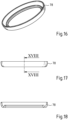
- the Fig. 16 is a perspective view of a ring body of the drinking vessel.
- the Fig. 17 shows a side view of the ring body of the drinking vessel.
- Fig. 18 is a section of the ring body of the drinking vessel along the line XVIII - XVIII from Fig. 17 .
- the annular shoulder 82 has a projection against which the cover element 78 rests in a force-fitting and form-fitting manner.
- the cover element 78 overlaps the coating 76 on the support structure 18 in a base region of the drinking vessel 10 (1) so that the coating is protected from mechanical damage.
- the drinking body 54 and the lid body 66 of the drinking vessel 10 (1) are made of a dishwasher-safe material.
- the lid body 66 is unscrewed from the drinking body 54, which in turn is separated from the holding structure 18.
- By then pulling in the direction of arrow 84 in Fig. 8 If a force is exerted on the container section 36, it can be pressed out of the holding structure 18 by the holding contour 57 of the ribs.
- a second drinking vessel 10 (2) is shown in a longitudinal section.
- Fig. 20 shows a cross section of the second drinking vessel in one of the lines XX - XX from Fig. 19 corresponding sectional plane.
- the assemblies and elements of the second drinking vessel 10 (2) correspond to the assemblies and elements of the first drinking vessel described above, they are identified by the same numbers as reference symbols.
- the second drinking vessel 10 (2) has a magnetic element 65 fixed in the holding structure 18, which holds the container 12, which here consists of a magnetic stainless steel, in its bottom-side container section 24 by means of a Magnetic force against a support section 22. Otherwise, the structure of the second drinking vessel 10 (2) corresponds to the structure of the first drinking vessel 10 (1) described above.
- a third drinking vessel 10 (3) is shown in a longitudinal section.
- Fig. 22 shows a cross section of the third drinking vessel in one of the lines XXII - XXII from Fig. 21 corresponding sectional plane.
- the assemblies and elements of the second drinking vessel 10 (2) correspond to the assemblies and elements of the first drinking vessel described above, they are identified by the same numbers as reference symbols.
- the container 12 is held in the holding structure 18 by means of a screw connection.
- the container bottom wall 14 of the container 12 here has an annular section 34, which is adjoined by a container section 36' with a cylindrical cross-section, which has an external thread 72.
- This external thread 72 is screwed into an internal thread 74 in the holding structure 18.
- the container 12 as the Fig. 21 and the Fig. 22 show, rotationally symmetrical in shape.
- the fourth drinking vessel 10 (4) shown is detachable and has an appearance that matches the design of a handbag.
- Fig. 24 is an exploded view of the drinking vessel 10 (4) . To the extent that the assemblies and elements of the fourth drinking vessel 10 (4) correspond to the assemblies and elements of the previously described drinking vessels 10 (1) , 10 (2) , and 10 (3) , they are identified by the same numbers as reference symbols.
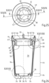
- FIG. 25 is a plan view of the drinking vessel in the direction of arrow XXV from Fig. 23 to see.
- the Fig. 26 shows a section of the drinking vessel along the line XXVI - XXVI from Fig. 25 .
- the Fig. 27 is an enlarged view of section XXVII from Fig. 26 .
- the hollow body of the holding structure 18 also has a cavity wall 20 which surrounds the side wall 16 of the container 12.
- the hollow body of the Support structure 18 also has a support section 22 which serves to support the container 12 in a bottom-side container section 24.
- the container 12 has an interior space 26 open on one side, which extends from the container bottom 28 in the bottom-side container section 24 to a container opening 30 having a circular opening edge 31.
- the container 12 has a container axis 32 perpendicular to the container opening 30 and extending through the center of the container opening 30, which is an axis of symmetry of the interior space 26.
- the Fig. 26 is a longitudinal section of the drinking vessel in a plane in which the container axis 32 runs.
- the container 12 has a container bottom wall 14 with an annular section 34, to which a container section 36 with a mounting structure is connected.
- the container section 36 with the mounting structure has, in the plane of a longitudinal section in which the container axis 32 runs, a dovetail-shaped cross-section with an outer contour that has an undercut. In the bottom-side container section 24, this outer contour partially follows the shape of a mushroom head.
- the mounting structure in the container section 36 protrudes through a container-bottom-side opening 38 of the hollow body of the holding structure 18.
- the container bottom-side opening 38 of the hollow body of the holding structure 18 is, as the Fig. 27 shows, delimited by elastic tongues 40, each having a circular-arc-shaped edge portion 42 facing the container axis 32, which bears against the container bottom wall 14 of the container 12 in the region of the undercut of the mounting structure in the container portion 36. Between the tongues 40 and the annular portion 34 of the container bottom wall 14, there is an annular air space 35, which isolates the container bottom wall 14 from the holding structure 18.
- the area of the cross section of the interior 26 of the container 12 perpendicular to the container axis 32 and the area of the cross section perpendicular to the container axis 32 vertical cross-section of the container 12 in a receiving section 44 of the container 12 for receiving a beverage up to a maximum value.
- the container 12 has an opening-side container section 46 connected to the receiving section 44 with the container opening 30, in which the maximum diameter of the interior 26 of the container 12 and the maximum diameter of the cross-section of the container 12 perpendicular to the container axis 32 are tapered compared to the maximum diameter of the interior 26 of the container 12 and the maximum diameter of the cross-section of the container 12 in the opening-side container section 46.
- the Fig. 28 is an enlarged view of section IIXX from Fig. 26 .
- the shell 48 of the container 12 is concavely curved.
- the Fig. 29 is another longitudinal section of the drinking vessel 10 (4) in one of the lines IXXX - IXXX from Fig. 25 corresponding cutting plane.
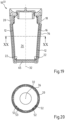
- the Fig. 30 shows a cross section of the drinking vessel in one of the lines XXX - XXX from Fig. 26 corresponding cutting plane.
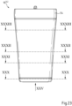
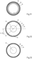
- the Fig. 31 , the Fig. 32 and the Fig. 33 Cross sections of the drinking vessel 10 corresponding to lines XXXI-XXXI, XXXII-XXXII and XXXIII-XXXIII can be seen.
- the inner and outer edges of the cross-section of the wall of the container 12 are circular, as the Fig. 30 Starting from the bottom-side container section 24, the diameter of the container 12 increases towards the container opening 30.
- the inner and outer edges of the cross-section of the wall of the container 12 are in the section planes corresponding to the lines XXXI-XXXI and XXXII-XXXII in Fig. 26 circular.
- the inner and outer edges of the cross-section of the wall of the container 12 in the area above the section plane corresponding to the line XXXII-XXXII in Fig. 26 corresponds to the course of the edge of a regular 16-gon.
- the container 12 thus has a rotational symmetry with respect to the container axis 32.
- the side wall 16 of the container 12 opposite the cavity wall 20 of the holding structure 18 has in the receiving section 44, as shown in the Fig. 31 , the Fig. 32 and the Fig. 33 can be seen, a circular cross-section.
- the inner circle and the outer circle of this circular cross-section lie here on a cone that is open in the direction of the container axis 32 pointing towards the container opening 30.
- rib-shaped support bodies 52 are arranged on the cavity wall 20 of the holding structure 18, regularly distributed over its inner circumference. These support bodies have support sections with support surfaces that rest against the side wall 16 of the container 12.
- the support bodies 52 extend in a longitudinal direction along a rib axis 55, which defines a plane with the direction of the container axis 32.
- the shell 48 of the container 12 is supported on the support bodies 52 in a cross-sectional plane perpendicular to the container axis 32 toward the cavity wall 20.
- the support bodies 52 bear against the respective straight second wall sections 47 of the side wall 16 of the container 12, whereby the container 12 is secured against rotation relative to the hollow body.
- the support bodies 52 of the holding structure 18 have a holding contour 57 which engages over a side wall portion 17 of the side wall 16 of the container 12 in a holding section 50 between the receiving section 44 and the opening-side container section 46.
- the holding contour 57 of the support bodies 52 engages over the side wall portion 17 of the side wall 16 of the container 12 in the holding section 50 and the concavely curved shell 48 of the container 12
- the container 12 is held in the holding structure 18 with a clamping force which presses the container 12 against the support section 22 of the holding structure, wherein the support sections 53 of the rib-shaped support bodies 52 bear against the shell 48 of the container 12.
- the side wall 16 of the container 12 is separated from the cavity wall 20 of the support structure 18 by an air-filled insulation space 43. This measure minimizes surface contact between the container 12 and the support structure 18, which counteracts the transfer of heat from a beverage in the container 12 to the support structure 18.
- the drinking vessel 10 (4) has a drinking body 54 in which a concave recess 56 is provided, forming an annular drinking bowl.
- the drinking body 54 has a metal section 63 on the drinking bowl side, which is firmly connected to a section 75 made of a plastic material on the container side.
- the drinking body 54 can also be made entirely of metal.
- the drinking body 54 has an external thread 60 in the container-side section 75 made of plastic material, which can be screwed onto an internal thread 58 formed in the opening-side container section 46 on the stainless steel container 12. This also ensures that no or at most minimal wear occurs on the container and drinking body when connecting the drinking body 54 to the container 12.
- Fig. 34 shows a handbag 86 and a drinking vessel 10, the appearance of which is adapted to the appearance of the handbag 86 by means of the cover 76 of the holding structure.
- the handbag 86 has a bag body 88 in which the drinking vessel 10 can be accommodated.
- Fig. 35 a section of the bag body 88 is seen from the inside.
- a holding device 90 which serves to hold the drinking vessel 10 in the bag body 88 of the handbag 86.
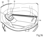
- the Fig. 36 shows the bag body 88 with the drinking vessel 10 accommodated in the holding device 90.
- the holding device 90 has a sleeve body 92 made of leather or a corresponding flexible material with a receptacle 94 adapted to the shape of the drinking vessel 10, in which the drinking vessel 10 can be held when the handbag is worn.
- the holding device 90 has a pocket 96, closable by means of a zipper 91, for holding objects such as coins, passports, or handkerchiefs, which is connected to the sleeve body 92.
- the holding device 90 is releasably secured to the handbag 86 by means of a releasable connection 98 of the cuff body 92 to the bag body 88, which connection is designed as a snap fastener device and forms a connection means for securing the holding device 90 in the bag body 88 of the handbag to the handbag 86.
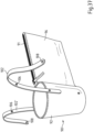
- the Fig. 37 shows a further, second holding device 90' for holding the drinking vessel 10 in the pocket body of a handbag.
- the components and elements of the further holding device 90' correspond to the components and elements of the holding device 90' described above, they are identified by the same numbers as reference symbols.
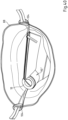
- the further holding device 90' with the bag body 88 of the handbag and the drinking vessel 10 accommodated in the further holding device 90' can be seen.
- a connection means for the releasable fixing of the holding device 90' in the bag body 88 of the handbag there are a first and a second strap 102, 102', each of which Strap lock 104 with a first lock part 106 and a second lock part 108 complementary to the first lock part 106, which serves for opening and closing a strap loop that can be placed around different carrying straps 110, 110' of the handbag 86 to hold the holding device 90 in the bag body 88.
- the first and second straps 102, 102' are here fixed to the sleeve body 92 of the holding device 90'.
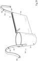
- the Fig. 39 shows a further, third holding device 90" for holding the drinking vessel 10 in the pocket body of a handbag.
- the further holding device 90" can be seen with the bag body 88 of the handbag and the drinking vessel 10.
- the assemblies and elements of the further holding device 90" correspond to the assemblies and elements of the holding device 90 described above, these are identified by the same numbers as reference symbols.
- connection means for releasably securing the holding device 90" in the bag body 88 of the handbag there are a first and a second strap 102, 102', each of which has a strap lock 104 with a first lock part 106 and a second lock part 108 complementary to the first lock part 106, which serves for opening and closing a strap loop that can be placed around the carrying strap 110 of the handbag 86 to hold the holding device 90 in the bag body 88.
- the first strap 102 is attached here to the sleeve body 92 of the holding device 90.
Landscapes
- Details Of Rigid Or Semi-Rigid Containers (AREA)
Applications Claiming Priority (3)
| Application Number | Priority Date | Filing Date | Title |
|---|---|---|---|
| DE102020124412.6A DE102020124412A1 (de) | 2020-09-18 | 2020-09-18 | Trinkgefäß mit Überzug sowie Handtasche und Haltevorrichtung für Trinkgefäß |
| PCT/EP2021/074089 WO2022058165A1 (fr) | 2020-09-18 | 2021-09-01 | Récipient à boire présentant une enveloppe et sac à mains et dispositif de maintien pour récipient à boire |
| EP21770202.6A EP4213681B1 (fr) | 2020-09-18 | 2021-09-01 | Récipient à boire présentant une enveloppe et sac à mains et dispositif de maintien pour récipient à boire |
Related Parent Applications (2)
| Application Number | Title | Priority Date | Filing Date |
|---|---|---|---|
| EP21770202.6A Division EP4213681B1 (fr) | 2020-09-18 | 2021-09-01 | Récipient à boire présentant une enveloppe et sac à mains et dispositif de maintien pour récipient à boire |
| EP21770202.6A Division-Into EP4213681B1 (fr) | 2020-09-18 | 2021-09-01 | Récipient à boire présentant une enveloppe et sac à mains et dispositif de maintien pour récipient à boire |
Publications (2)
| Publication Number | Publication Date |
|---|---|
| EP4533983A2 true EP4533983A2 (fr) | 2025-04-09 |
| EP4533983A3 EP4533983A3 (fr) | 2025-07-30 |
Family
ID=77774905
Family Applications (2)
| Application Number | Title | Priority Date | Filing Date |
|---|---|---|---|
| EP25159245.7A Pending EP4533983A3 (fr) | 2020-09-18 | 2021-09-01 | Récipient à boire présentant une enveloppe et sac à mains et dispositif de maintien pour récipient à boire |
| EP21770202.6A Active EP4213681B1 (fr) | 2020-09-18 | 2021-09-01 | Récipient à boire présentant une enveloppe et sac à mains et dispositif de maintien pour récipient à boire |
Family Applications After (1)
| Application Number | Title | Priority Date | Filing Date |
|---|---|---|---|
| EP21770202.6A Active EP4213681B1 (fr) | 2020-09-18 | 2021-09-01 | Récipient à boire présentant une enveloppe et sac à mains et dispositif de maintien pour récipient à boire |
Country Status (6)
| Country | Link |
|---|---|
| US (1) | US20230270238A1 (fr) |
| EP (2) | EP4533983A3 (fr) |
| CN (1) | CN116322424A (fr) |
| CA (1) | CA3191981A1 (fr) |
| DE (1) | DE102020124412A1 (fr) |
| WO (1) | WO2022058165A1 (fr) |
Families Citing this family (1)
| Publication number | Priority date | Publication date | Assignee | Title |
|---|---|---|---|---|
| USD1116615S1 (en) * | 2024-08-02 | 2026-03-10 | Ningbo Zhongyi Product Design Co., Ltd. | Cup |
Citations (8)
| Publication number | Priority date | Publication date | Assignee | Title |
|---|---|---|---|---|
| US4823974A (en) | 1987-10-20 | 1989-04-25 | Crosser Hayward B | Chill cylinder for beverage containers |
| US5813445A (en) | 1996-12-23 | 1998-09-29 | Christman; Lynn R. | Bingo tote bag |
| DE202004004193U1 (de) | 2004-03-16 | 2004-06-09 | Genzler, Martin | Isolierende Umhüllung für Flaschen, Dosen, Becher, Gläser und ähnliche Gegenstände |
| DE202004014541U1 (de) | 2004-09-16 | 2004-12-09 | Ebeling, Jens | Trinkglas oder Becher mit einer Verkleidung |
| US7198171B2 (en) | 2003-11-13 | 2007-04-03 | Pacific Cornetta, Inc. | Liquid holding vessel with separately attached handle |
| US20080087786A1 (en) | 2006-10-16 | 2008-04-17 | Calibre International, Llc | Bean bag holder to be used to hold a can or bottle |
| CN105640222A (zh) | 2015-12-22 | 2016-06-08 | 苏州征之魂专利技术服务有限公司 | 控温杯子 |
| CN209528789U (zh) | 2019-01-30 | 2019-10-25 | 台州市泰澄电子科技有限公司 | 一种杯子 |
Family Cites Families (9)
| Publication number | Priority date | Publication date | Assignee | Title |
|---|---|---|---|---|
| US6352168B1 (en) * | 2001-06-21 | 2002-03-05 | Jung-Chuang Lin | Rotation cup |
| CN2675597Y (zh) * | 2004-02-26 | 2005-02-02 | 孟思明 | 带有覆盖物的饮品瓶 |
| US7878365B1 (en) * | 2006-08-29 | 2011-02-01 | Timemug Llc | Theme mug with timepiece |
| US9061795B2 (en) * | 2007-08-20 | 2015-06-23 | Procter & Gamble | Supportable pressurizable container and base cup therefor with alignment tabs |
| CN104687680A (zh) * | 2013-12-06 | 2015-06-10 | 青岛嘉能节能环保技术有限公司 | 内置固定水杯手提包 |
| US10021956B2 (en) * | 2015-08-26 | 2018-07-17 | Franklin D. Clark | Modular water bottle system |
| CN109561772A (zh) * | 2016-05-04 | 2019-04-02 | 哈迪·斯坦曼 | 便携式饮料容器 |
| CN110522143A (zh) * | 2018-05-24 | 2019-12-03 | 广州市贝必凯设计有限公司 | 水瓶套的手提包连接结构 |
| CN209404307U (zh) * | 2018-11-28 | 2019-09-20 | 浙江雄泰家居用品股份有限公司 | 一种带磁铁助力的保温杯 |
-
2020
- 2020-09-18 DE DE102020124412.6A patent/DE102020124412A1/de active Pending
-
2021
- 2021-09-01 EP EP25159245.7A patent/EP4533983A3/fr active Pending
- 2021-09-01 EP EP21770202.6A patent/EP4213681B1/fr active Active
- 2021-09-01 US US18/044,225 patent/US20230270238A1/en not_active Abandoned
- 2021-09-01 CN CN202180063989.9A patent/CN116322424A/zh active Pending
- 2021-09-01 CA CA3191981A patent/CA3191981A1/fr active Pending
- 2021-09-01 WO PCT/EP2021/074089 patent/WO2022058165A1/fr not_active Ceased
Patent Citations (8)
| Publication number | Priority date | Publication date | Assignee | Title |
|---|---|---|---|---|
| US4823974A (en) | 1987-10-20 | 1989-04-25 | Crosser Hayward B | Chill cylinder for beverage containers |
| US5813445A (en) | 1996-12-23 | 1998-09-29 | Christman; Lynn R. | Bingo tote bag |
| US7198171B2 (en) | 2003-11-13 | 2007-04-03 | Pacific Cornetta, Inc. | Liquid holding vessel with separately attached handle |
| DE202004004193U1 (de) | 2004-03-16 | 2004-06-09 | Genzler, Martin | Isolierende Umhüllung für Flaschen, Dosen, Becher, Gläser und ähnliche Gegenstände |
| DE202004014541U1 (de) | 2004-09-16 | 2004-12-09 | Ebeling, Jens | Trinkglas oder Becher mit einer Verkleidung |
| US20080087786A1 (en) | 2006-10-16 | 2008-04-17 | Calibre International, Llc | Bean bag holder to be used to hold a can or bottle |
| CN105640222A (zh) | 2015-12-22 | 2016-06-08 | 苏州征之魂专利技术服务有限公司 | 控温杯子 |
| CN209528789U (zh) | 2019-01-30 | 2019-10-25 | 台州市泰澄电子科技有限公司 | 一种杯子 |
Also Published As
| Publication number | Publication date |
|---|---|
| WO2022058165A1 (fr) | 2022-03-24 |
| EP4213681C0 (fr) | 2025-04-02 |
| EP4213681A1 (fr) | 2023-07-26 |
| DE102020124412A1 (de) | 2022-03-24 |
| CA3191981A1 (fr) | 2022-03-24 |
| US20230270238A1 (en) | 2023-08-31 |
| CN116322424A (zh) | 2023-06-23 |
| EP4533983A3 (fr) | 2025-07-30 |
| EP4213681B1 (fr) | 2025-04-02 |
Similar Documents
| Publication | Publication Date | Title |
|---|---|---|
| DE69319109T2 (de) | Trinkgefäss geignet zur verwendung als schnabeltasse oder dergleichen | |
| DE69838255T2 (de) | Auslaufgeschützter trinkbecher | |
| DE60219644T2 (de) | Entfernbarer tabletteinsatz und tablett-set | |
| US7121431B2 (en) | Battlefield flask | |
| DE68917681T2 (de) | Gefässdeckel. | |
| US20170057691A1 (en) | Modular Water Bottle System | |
| DE3714326A1 (de) | Babyflasche mit wegwerf-einsatz | |
| EP4213681B1 (fr) | Récipient à boire présentant une enveloppe et sac à mains et dispositif de maintien pour récipient à boire | |
| EP2708220A2 (fr) | Enveloppe de biberon | |
| WO2016163924A1 (fr) | Récipient pour boisson comportant un système de support | |
| DE102017005112A1 (de) | Behälter zur Aufnahme eines Getränkes und Umhüllung | |
| US20240349920A1 (en) | Drinking vessel with covering, and handbag and holding device for drinking vessel | |
| US6308859B1 (en) | Communion cup | |
| DE69931264T2 (de) | Auslaufgeschütztes trinkbecher | |
| DE9303550U1 (de) | Wärmeisolierende Transportvorrichtung für Speisen | |
| US6488169B1 (en) | Combination flask for pills and liquid therefor | |
| DE29703776U1 (de) | Hygienischer Verschluß für Behälter, wie Flaschen, Dosen o.dgl. zum Aufnehmen, Wiedergeben und/oder Aufbewahren von Flüssigkeiten, wie Getränken, Medikamenten u.a. | |
| DE3320171A1 (de) | Geschirr zum kochen, aufbewahren und transportieren von lebensmitteln | |
| DE102007048732A1 (de) | Trinkhilfe | |
| CA2417447C (fr) | Dispositif de rincage des yeux facile a porter | |
| DE19617328C1 (de) | Etui, insbesondere für Schlüssel und dgl. | |
| DE19705282C2 (de) | Auslaufgeschützter Trinkgefäß-Aufsatz | |
| RU2156215C1 (ru) | Тара для напитков | |
| DE202022106157U1 (de) | Becher-in-Becher-Trinkgefäß | |
| AT520160B1 (de) | Tragtasche |
Legal Events
| Date | Code | Title | Description |
|---|---|---|---|
| PUAI | Public reference made under article 153(3) epc to a published international application that has entered the european phase |
Free format text: ORIGINAL CODE: 0009012 |
|
| STAA | Information on the status of an ep patent application or granted ep patent |
Free format text: STATUS: THE APPLICATION HAS BEEN PUBLISHED |
|
| REG | Reference to a national code |
Ref country code: DE Ref legal event code: R079 Free format text: PREVIOUS MAIN CLASS: A47G0019220000 Ipc: A45C0011200000 |
|
| AC | Divisional application: reference to earlier application |
Ref document number: 4213681 Country of ref document: EP Kind code of ref document: P |
|
| AK | Designated contracting states |
Kind code of ref document: A2 Designated state(s): AL AT BE BG CH CY CZ DE DK EE ES FI FR GB GR HR HU IE IS IT LI LT LU LV MC MK MT NL NO PL PT RO RS SE SI SK SM TR |
|
| RIC1 | Information provided on ipc code assigned before grant |
Ipc: A47G 19/22 20060101ALI20250401BHEP Ipc: A45F 3/18 20060101ALI20250401BHEP Ipc: A45C 15/00 20060101ALI20250401BHEP Ipc: A45C 13/02 20060101ALI20250401BHEP Ipc: A45C 11/20 20060101AFI20250401BHEP |
|
| PUAL | Search report despatched |
Free format text: ORIGINAL CODE: 0009013 |
|
| AK | Designated contracting states |
Kind code of ref document: A3 Designated state(s): AL AT BE BG CH CY CZ DE DK EE ES FI FR GB GR HR HU IE IS IT LI LT LU LV MC MK MT NL NO PL PT RO RS SE SI SK SM TR |
|
| RIC1 | Information provided on ipc code assigned before grant |
Ipc: A45C 11/20 20060101AFI20250625BHEP Ipc: A45C 13/02 20060101ALI20250625BHEP Ipc: A45C 15/00 20060101ALI20250625BHEP Ipc: A45F 3/18 20060101ALI20250625BHEP Ipc: A47G 19/22 20060101ALI20250625BHEP |
|
| STAA | Information on the status of an ep patent application or granted ep patent |
Free format text: STATUS: REQUEST FOR EXAMINATION WAS MADE |
|
| 17P | Request for examination filed |
Effective date: 20260120 |