EP4533986A2 - Appareil de montage pour une plaque de cuisson doté d'une poignée et procédé de fonctionnement d'un appareil de montage - Google Patents
Appareil de montage pour une plaque de cuisson doté d'une poignée et procédé de fonctionnement d'un appareil de montage Download PDFInfo
- Publication number
- EP4533986A2 EP4533986A2 EP25153121.6A EP25153121A EP4533986A2 EP 4533986 A2 EP4533986 A2 EP 4533986A2 EP 25153121 A EP25153121 A EP 25153121A EP 4533986 A2 EP4533986 A2 EP 4533986A2
- Authority
- EP
- European Patent Office
- Prior art keywords
- hob
- stand
- touch sensor
- handle
- operating
- Prior art date
- Legal status (The legal status is an assumption and is not a legal conclusion. Google has not performed a legal analysis and makes no representation as to the accuracy of the status listed.)
- Pending
Links
Images

Classifications
-
- A—HUMAN NECESSITIES
- A47—FURNITURE; DOMESTIC ARTICLES OR APPLIANCES; COFFEE MILLS; SPICE MILLS; SUCTION CLEANERS IN GENERAL
- A47J—KITCHEN EQUIPMENT; COFFEE MILLS; SPICE MILLS; APPARATUS FOR MAKING BEVERAGES
- A47J45/00—Devices for fastening or gripping kitchen utensils or crockery
- A47J45/06—Handles for hollow-ware articles
- A47J45/068—Handles having indicating means, e.g. for temperature
-
- A—HUMAN NECESSITIES
- A47—FURNITURE; DOMESTIC ARTICLES OR APPLIANCES; COFFEE MILLS; SPICE MILLS; SUCTION CLEANERS IN GENERAL
- A47J—KITCHEN EQUIPMENT; COFFEE MILLS; SPICE MILLS; APPARATUS FOR MAKING BEVERAGES
- A47J36/00—Parts, details or accessories of cooking-vessels
- A47J36/32—Time-controlled igniting mechanisms or alarm devices
- A47J36/321—Time-controlled igniting mechanisms or alarm devices the electronic control being performed over a network, e.g. by means of a handheld device
-
- A—HUMAN NECESSITIES
- A47—FURNITURE; DOMESTIC ARTICLES OR APPLIANCES; COFFEE MILLS; SPICE MILLS; SUCTION CLEANERS IN GENERAL
- A47J—KITCHEN EQUIPMENT; COFFEE MILLS; SPICE MILLS; APPARATUS FOR MAKING BEVERAGES
- A47J45/00—Devices for fastening or gripping kitchen utensils or crockery
- A47J45/06—Handles for hollow-ware articles
-
- F—MECHANICAL ENGINEERING; LIGHTING; HEATING; WEAPONS; BLASTING
- F24—HEATING; RANGES; VENTILATING
- F24C—DOMESTIC STOVES OR RANGES ; DETAILS OF DOMESTIC STOVES OR RANGES, OF GENERAL APPLICATION
- F24C7/00—Stoves or ranges heated by electric energy
- F24C7/08—Arrangement or mounting of control or safety devices
- F24C7/082—Arrangement or mounting of control or safety devices on ranges, e.g. control panels, illumination
- F24C7/083—Arrangement or mounting of control or safety devices on ranges, e.g. control panels, illumination on tops, hot plates
Definitions
- the invention relates to a stand-up device for a hob with a handle of the type mentioned in the preamble of patent claim 1 and a method for operating a stand-up device.
- Such stand-alone appliances comprise, for example, at least one handle with a gripping section having at least one gripping area integrated in the handle for gripping the stand-alone appliance with a user's hand, a controller, and a transmitting unit connected to the controller for signal transmission for signal transmission from the stand-alone appliance to the hob, wherein the gripping area has at least one touch sensor connected to the controller for signal transmission for detecting the gripping of the handle.
- the printed publications CN 105 747 836 A and DE 10 2019 126 830 A1 are included in the printed publications CN 105 747 836 A and DE 10 2019 126 830 A1 .
- the DE 10 2018 110 125 A1 A preparation device for food and/or liquid on a hob or in a cooking chamber is known, comprising at least one scale for weighing food and/or liquid poured into the preparation device and at least one handle for handling the preparation device.
- the at least one scale is arranged in the at least one handle of the preparation device.
- the publication shows WO 2020 153 826 A1 a cooking container with a handle, with a control element integrated into the handle.
- the invention therefore addresses the problem of improving a stand-up device for a hob and a method for operating a stand-up device that can be set up on a hob.
- the advantage achievable with the invention is, in particular, that a stand-up device for a hob and a method for operating a stand-up device are improved.
- the inventive design of the stand-alone appliance for placement on a hob and the method for operating such a stand-alone appliance enables, on the one hand, cost-effective user recognition of a user using the stand-alone appliance.
- the provision of at least one touch sensor in the gripping section for detecting a touch of the handle by the user for the purpose of manually moving the stand-alone appliance automatically detects the user's intention to grasp the stand-alone appliance.
- the invention makes it possible to estimate the fill level of the stand-alone appliance, i.e., the fill weight of a food item and/or a liquid filled into the stand-alone appliance, without great effort. Furthermore, the invention makes it possible to determine the user's behavior when using the stand-alone appliance, so that, for example, the user's interaction with the stand-alone appliance can be determined without additional means. This also makes it possible to significantly improve the safety of using the stand-alone appliance and/or the hob without reducing the ease of use for the user of the stand-alone appliance. For example, user profiles for individual users could be stored in the control system of the appliance, so that certain users or user groups, such as users with limited abilities and/or children, can only use the appliance and/or the cooktop within predefined limits. Artificial intelligence technology could also be used here.
- the stand-alone appliance can be freely selected within wide, suitable limits in terms of type, functionality, dimensions, and material.
- the stand-alone appliance can be designed, for example, as a pan or a pot. However, other embodiments such as a kettle, roasting pan, or the like are also conceivable.
- the stand-alone appliance can have one or more handles, whereby the inventive design of the handle can be present in just one of the handles or in a plurality of handles.
- the at least one gripping section with the gripping area is designed as a touch-sensitive area of the handle by means of the at least one touch sensor. In other embodiments, the at least one gripping area can additionally be designed as a proximity-sensitive area.
- the at least one gripping area can be arranged on the handle so that it is visible or invisibly visible from the outside.
- the at least one gripping area can be fully integrated into the handle, so that this gripping area is neither visible nor palpable from the outside.
- the stand-alone appliance can be designed to be suitable for an induction hob. However, this is not absolutely necessary.
- the installation device according to the invention can be designed to be suitable for all conceivable types of hob.
- the further processing of the detection of a touch of the handle by the user i.e. the method for processing the detection of a touch of the handle by the user, within wide, suitable limits.
- a particularly advantageous development of the stand-up device according to the invention provides that the touch sensor is arranged on the handle or integrated into the handle in such a way that the touch sensor can be reliably touched when the handle is grasped by the hand using at least one finger. This ensures that grasping the handle, i.e., the gripping by the user, is reliably detected.
- the at least one touch sensor is designed as at least a first touch sensor and a second touch sensor, wherein, when the stand-alone device is placed on the hob, the first touch sensor is arranged on the side of the handle facing the hob and the second touch sensor is arranged on the side of the handle facing away from the hob.
- This further simplifies the handling of the stand-alone device without compromising the functional reliability when detecting gripping by means of the at least one touch sensor. Accordingly, the ergonomics when using the stand-alone device according to the invention are further improved.
- the touch sensor to be designed as a touch-sensitive film.
- Films are particularly easy to apply to a handle for a stand-up device.
- touch-sensitive films can be very easily arranged in a form-fitting manner and tightly against the handle, so that the functionality of the touch sensor is not impaired by environmental conditions occurring during cooking or roasting.
- One aspect is to implement the touch sensor or a touch-sensitive area as a glass cover.
- the touch sensor is arranged below the glass cover, and the glass cover forms a portion of the outer surface of the stand-up device.
- the stand-alone device has at least one input unit connected to the control unit in a signal-transmitting manner, with at least one input area integrated in the handle for the input of a user command by the user of the stand-alone device, wherein the input area is arranged in an input section that is positioned differently from the gripping section, and the stand-alone device and/or the hob can be controlled by means of the user command.
- the safety when operating the stand-alone device and in particular the safety when operating the hob is significantly improved, without thereby impairing the operating comfort for the user of the stand-alone device. is reduced.
- the clear spatial separation of the handle into a gripping section and the at least one input section effectively counteracts unintentional operation of the at least one input area of the at least one input unit when the handle is gripped for manual movement of the stand-up device.
- the stand-up device according to the invention thus enables a distinction to be made between operation of the handle for the purpose of entering a user command on the one hand and operation of the handle for the purpose of manual movement of the stand-up device on the other hand.
- the touch sensor can be designed, for example, as a capacitive sensor.
- the control of the stand-alone appliance and/or a hob control of the hob can be transferred from a standby mode into a ready mode or an operating mode, wherein the control and/or hob control are/is designed in the standby mode essentially only to transfer to the ready mode or the operating mode, in the ready mode to assign the stand-alone appliance to a cooking zone of the hob, and in the operating mode to operate the stand-alone appliance and/or the hob with their full range of functions.
- This enables, on the one hand, energy-saving operation of the stand-alone appliance and/or the hob.
- this further increases operating convenience while simultaneously ensuring safety when operating the stand-alone appliance and the hob.
- a further advantageous development of the stand-alone device provides that the touch sensor is simultaneously designed as a further input area for entering a further user command for controlling the stand-alone device and/or the hob, preferably that the stand-alone device and/or the hob can be switched on by the control system as a function of the detection of the touch of the handle.
- the at least one touch sensor simultaneously for the intuitive input of a further user command by the user.
- the functionality of the at least one touch sensor is thus increased.
- This input of a further user command can be carried out in addition to or as an alternative to the input of a user command using the aforementioned at least one input area.
- the method according to the invention can be freely selected within wide suitable limits.
- an advantageous development of the method according to the invention provides that by means of the at least one touch sensor, a filling weight of a food item and/or liquid filled into the stand-alone appliance is detected, and/or an individual handling the stand-alone appliance and/or a member of a group of people handling the stand-alone appliance is detected, and/or the at least one touch sensor is simultaneously used as a further input area for entering a further user command for controlling the stand-alone appliance and/or the hob, preferably that a handling interaction of the user with the stand-alone appliance is detected and/or a hob action is started and/or set and/or ended.
- a first embodiment of the inventive installation device for a hob for carrying out the inventive method is shown purely by way of example.
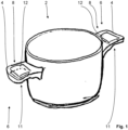
- the stand-up device 2 is designed here as a cooking pot for placement on a cooking hob (not shown) and comprises two handles 4, each with a gripping section 6, each with a gripping area 8 integrated in the handle 4 for grasping the stand-up device 2 with a hand 10 of a user (not shown in detail), a control (not shown) and a transmitting unit (likewise not shown) connected to the control for signal transmission for signal transmission from the stand-up device 2 to the cooking hob, wherein the gripping area 8 has two touch sensors connected to the control for signal transmission, namely a first touch sensor 11 facing the cooking hob when the stand-up device 2 is placed on the cooking hob and a second touch sensor 12 facing the cooking hob when the stand-up device 2 is placed on the cooking hob. second touch sensor 12 facing away from the hob, for detecting the gripping of the handle 4.
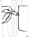
- the first and second touch sensors 11, 12 are each designed for the substantially simultaneous detection of a force and a position of at least one finger, for example the thumb 14, the index finger 16 and the middle finger 18 of the left hand 10, wherein the transmitting unit (not shown) connected to the control unit for signal transmission can be controlled to control the hob depending on the output signals of the touch sensors 11, 12.
- the transmitting unit (not shown) connected to the control unit for signal transmission can be controlled to control the hob depending on the output signals of the touch sensors 11, 12.
- an output unit of the stand-up device for outputting acoustic and/or visual information to the user of the stand-up device can be controlled by means of the output signals of the at least one touch sensor.
- the touch sensors 11, 12 are integrated in the respective handle 4 in such a way that the respective touch sensor 11, 12 can be reliably touched when the corresponding handle 4 is grasped with the hand 10 by means of the at least one finger 14, 16, 18.
- the two handles 4 are identical to one another in the present embodiment, so that explanations regarding the device shown in the image plane of the Fig. 1 Handle 4 shown on the left also represents the one in the image plane of the Fig. 1
- the handle 4 shown on the right applies.
- To facilitate integration of the touch sensors 11, 12, they are each designed as a touch-sensitive foil.
- the stand-alone appliance 2 is further designed and configured such that the control and a hob control (not shown) of the hob (likewise not shown) can be transferred from a standby mode into a standby mode or an operating mode depending on the touch of the respective handle 4 detected by the touch sensors 11, 12, wherein the control and/or the hob control in the standby mode are designed essentially only for transferring to the standby mode or the operating mode, in the standby mode for assigning the stand-alone appliance 2 to a cooking zone (not shown) of the hob, and in the operating mode for operating the stand-alone appliance 2 and the hob with their full range of functions.
- the respective touch sensor 11, 12 of each of the handles 4 is simultaneously designed as a further input area for entering a further user command for controlling the hob, namely in such a way that the installation device and the hob in Depending on the detection of the touch of the respective handle 4, they can be switched on by means of the controller.
- the use of the terms "further input area” and “further user command” serves solely to differentiate between a possibly alternative or additional input area for entering user commands, which will be explained in more detail below.
- the control of the installation device 2 and the hob control of the hob are transferred from the respective standby mode into a standby mode or an operating mode, wherein the control and hob control in the standby mode are essentially only transferred into the standby mode or the operating mode, in the standby mode they assign the installation device 2 to one of the cooking zones of the hob and in the operating mode they operate the installation device 2 and the hob with their full range of functions.
- the control of the stand-up device 2 and the hob control of the hob are transferred from the respective standby mode to the respective standby mode or the respective operating mode, provided that a touch of one of the handles 4 has been detected by the corresponding touch sensors 11, 12.
- the stand-up device 2 and the hob are switched on by the control depending on the detection of the touch of one of the two handles 4.
- the touch sensors 11, 12 are also used here for at least one further function, namely for inputting a further user command.
- at least one of the at least one touch sensor 11, 12 is designed to detect a rotational movement of the human hand 10 relative to the respective handle 4, wherein the further user command is input by the user depending on the detection of the rotational movement.
- the user could increase or decrease the power level for this cooking zone depending on the direction of rotation by rotating their hand 10 around an axis of the handle 4, i.e., by moving the fingers 14, 16, 18 relative to the respective corresponding touch sensor 11, 12.
- control system automatically reduces the power of the hob in order to effectively protect, for example, sensitive components of the hob which could be impaired in their function or damaged due to mechanical stress occurring when the installation device 2 is manually moved by a user.
- the touch sensors 11, 12 detect, for example, the filling weight of a food item and/or liquid placed in the appliance 2.
- the food item and the liquid are in the Fig. 1 and 2 not shown.
- an individual handling the stand-up device 2, i.e. the specific user of the stand-up device 2 is recognized by means of the touch sensors 11, 12.
- a member of a group of people handling the stand-up device 2, for example a child or an adult with limited abilities is recognized by means of the touch sensors 11, 12.
- the respective gripping area 8 can thus simultaneously be used as a further input area for entering a further user command for controlling the stand-up device 2 and/or the hob, namely in such a way that, for example, a handling interaction of the user with the stand-up device 2 is recognized and/or a hob action is started and/or set and/or ended.
- the stand-alone appliance 2 can be used in a wide variety of ways. Based on the forces measured by the touch sensors 11, 12, it is thus possible to automatically detect how full the stand-alone appliance 2 is with food and/or liquid. This information can be used accordingly to provide cooking assistance via a cooking assistance system, and the cooking assistance can be adapted to individual requirements. Furthermore, critical situations during cooking or frying can be detected or avoided in a timely manner. Furthermore, user actions, i.e. interactions between the user and the stand-alone appliance 2, can be implemented to save energy and/or increase safety when using the stand-alone appliance 2 and/or the hob on which the stand-alone appliance 2 is installed.
- FIG. 3 a second embodiment of the installation device according to the invention is shown.
- the installation device 2 of the second embodiment is designed as a pan and, in contrast to the first embodiment, has only a single handle 4, namely a bar handle. Otherwise, the second embodiment corresponds to the first embodiment according to the Fig. 1 and 2 , so that reference is made to the above explanations regarding the first embodiment.
- the stand-up device 2 Due to the inventive design of the stand-up device 2 for placement on the hob and the method for operating the stand-up device 2, on the one hand, cost-effective user recognition of the user using the stand-up device 2 is enabled.
- the provision of at least one touch sensor 11, 12 in the gripping section 6 for detecting a touch of the handle 4 by the user for the purpose of manually moving the stand-up device 2 automatically detects the user's intention to grasp the stand-up device 2.
- a fill level of the stand-up device 2 i.e. a fill weight of a food item and/or a liquid filled into the stand-up device 2, can be estimated without much effort.
- the installation device 2 and the corresponding method it is possible to determine the behavior of the user when using the installation device 2, so that, for example, the interaction of the user with the installation device 2 can be determined without additional means. This can also significantly improve the safety when using the installation device 2 and the hob without reducing the ease of use for the user of the installation device 2.
- user profiles for individual users could be stored in the control system of the installation device 2, so that certain users or user groups, such as users with limited abilities and/or children, can only use the installation device 2 and the hob within predetermined limits.
- the technology of so-called artificial intelligence can be used here.
- the stand-alone appliance can also be designed as a kettle, roasting pan, or the like. Depending on the design of the stand-alone appliance, the stand-alone appliance can have one or more handles, whereby the handle design according to the invention can be present in just one of the handles or in multiple handles.
- the stand-alone appliance can be designed to be suitable for an induction hob. However, this is not mandatory.
- the stand-alone appliance according to the invention can be designed to be suitable for all conceivable hob types.
- the at least one touch sensor can be freely selected within wide, suitable limits in terms of type, functionality, dimensions, material, number, and arrangement. The above explanations are therefore to be understood as examples only and not as limiting. Depending on the application, the person skilled in the art will select the at least one Select a suitable touch sensor and, for example, combine different sensor technologies.
- the stand-alone appliance according to the invention can also have a receiving unit for transmitting signals from the hob to the stand-alone appliance. It is also conceivable that the transmitting unit of the stand-alone appliance according to the invention is designed as a combined transmitting/receiving unit.
- the stand-alone device alternatively or in addition to the aforementioned further input area, has at least one input unit connected to the controller in a signal-transmitting manner, with at least one input area integrated in the handle for the user of the stand-alone device to enter a user command, wherein the input area is arranged in an input section that is positioned differently from the gripping section, and the stand-alone device and/or the hob can be controlled by means of the user command.
- the safety when operating the stand-alone device and in particular the safety when operating the hob is significantly improved without reducing the ease of use for the user of the stand-alone device.
- the clear spatial separation of the handle into a gripping section and the at least one input section effectively counteracts unintentional operation of the at least one input area of the at least one input unit when grasping the handle to manually move the stand-alone device.
- the stand-up device according to the invention thus allows a distinction to be made between operating the handle for the purpose of entering a user command on the one hand and operating the handle for the purpose of manually moving the stand-up device on the other hand.
- the at least one input area can be arranged on the handle so that it is visible or invisibly visible from the outside.
- the at least one input area can be fully integrated into the handle, so that this input area is neither visible nor tangible from the outside.
- the touch sensor can be designed, for example, as a capacitive sensor.
Landscapes
- Engineering & Computer Science (AREA)
- Food Science & Technology (AREA)
- Chemical & Material Sciences (AREA)
- Combustion & Propulsion (AREA)
- Mechanical Engineering (AREA)
- General Engineering & Computer Science (AREA)
- Cookers (AREA)
- Bending Of Plates, Rods, And Pipes (AREA)
Applications Claiming Priority (3)
| Application Number | Priority Date | Filing Date | Title |
|---|---|---|---|
| DE102021131336.8A DE102021131336A1 (de) | 2021-11-30 | 2021-11-30 | Aufstellgerät für ein Kochfeld mit einem Griff und Verfahren zum Betrieb eines Aufstellgeräts |
| EP22814387.1A EP4440390A1 (fr) | 2021-11-30 | 2022-11-09 | Appareil autonome pour plaque de cuisson comprenant une poignée et procédé de fonctionnement d'un appareil autonome |
| PCT/EP2022/081305 WO2023099140A1 (fr) | 2021-11-30 | 2022-11-09 | Appareil autonome pour plaque de cuisson comprenant une poignée et procédé de fonctionnement d'un appareil autonome |
Related Parent Applications (1)
| Application Number | Title | Priority Date | Filing Date |
|---|---|---|---|
| EP22814387.1A Division EP4440390A1 (fr) | 2021-11-30 | 2022-11-09 | Appareil autonome pour plaque de cuisson comprenant une poignée et procédé de fonctionnement d'un appareil autonome |
Publications (2)
| Publication Number | Publication Date |
|---|---|
| EP4533986A2 true EP4533986A2 (fr) | 2025-04-09 |
| EP4533986A3 EP4533986A3 (fr) | 2025-08-13 |
Family
ID=84367347
Family Applications (3)
| Application Number | Title | Priority Date | Filing Date |
|---|---|---|---|
| EP25170985.3A Pending EP4599742A1 (fr) | 2021-11-30 | 2022-11-09 | Appareil autonome pour plaque de cuisson comprenant une poignée et procédé de fonctionnement d'un appareil autonome |
| EP22814387.1A Pending EP4440390A1 (fr) | 2021-11-30 | 2022-11-09 | Appareil autonome pour plaque de cuisson comprenant une poignée et procédé de fonctionnement d'un appareil autonome |
| EP25153121.6A Pending EP4533986A3 (fr) | 2021-11-30 | 2022-11-09 | Appareil de montage pour une plaque de cuisson doté d'une poignée et procédé de fonctionnement d'un appareil de montage |
Family Applications Before (2)
| Application Number | Title | Priority Date | Filing Date |
|---|---|---|---|
| EP25170985.3A Pending EP4599742A1 (fr) | 2021-11-30 | 2022-11-09 | Appareil autonome pour plaque de cuisson comprenant une poignée et procédé de fonctionnement d'un appareil autonome |
| EP22814387.1A Pending EP4440390A1 (fr) | 2021-11-30 | 2022-11-09 | Appareil autonome pour plaque de cuisson comprenant une poignée et procédé de fonctionnement d'un appareil autonome |
Country Status (4)
| Country | Link |
|---|---|
| US (1) | US20250009183A1 (fr) |
| EP (3) | EP4599742A1 (fr) |
| DE (1) | DE102021131336A1 (fr) |
| WO (1) | WO2023099140A1 (fr) |
Citations (4)
| Publication number | Priority date | Publication date | Assignee | Title |
|---|---|---|---|---|
| CN105747836A (zh) | 2016-04-19 | 2016-07-13 | 北京小米移动软件有限公司 | 烹饪锅 |
| DE102018110125A1 (de) | 2018-04-26 | 2019-10-31 | Miele & Cie. Kg | Zubereitungsgerät für Nahrung und/oder Flüssigkeit mit einer Waage |
| WO2020153826A1 (fr) | 2019-01-25 | 2020-07-30 | 엘지전자 주식회사 | Bouilloire électrique |
| EP3893603A1 (fr) | 2020-04-06 | 2021-10-13 | Miele & Cie. KG | Système de cuisine à induction |
Family Cites Families (3)
| Publication number | Priority date | Publication date | Assignee | Title |
|---|---|---|---|---|
| GB2425037A (en) | 2005-02-16 | 2006-10-18 | Shane Allen Carr | Indicating the amount of water in a kettle |
| US20190125120A1 (en) | 2016-02-18 | 2019-05-02 | Meyer Intellectual Properties Limited | Cooking system for tracking a cooking device |
| DE102019126830A1 (de) | 2019-10-07 | 2021-04-08 | Miele & Cie. Kg | Aufstellgerät für ein Kochfeld mit einem Griff |
-
2021
- 2021-11-30 DE DE102021131336.8A patent/DE102021131336A1/de active Pending
-
2022
- 2022-11-09 WO PCT/EP2022/081305 patent/WO2023099140A1/fr not_active Ceased
- 2022-11-09 EP EP25170985.3A patent/EP4599742A1/fr active Pending
- 2022-11-09 EP EP22814387.1A patent/EP4440390A1/fr active Pending
- 2022-11-09 US US18/711,623 patent/US20250009183A1/en active Pending
- 2022-11-09 EP EP25153121.6A patent/EP4533986A3/fr active Pending
Patent Citations (4)
| Publication number | Priority date | Publication date | Assignee | Title |
|---|---|---|---|---|
| CN105747836A (zh) | 2016-04-19 | 2016-07-13 | 北京小米移动软件有限公司 | 烹饪锅 |
| DE102018110125A1 (de) | 2018-04-26 | 2019-10-31 | Miele & Cie. Kg | Zubereitungsgerät für Nahrung und/oder Flüssigkeit mit einer Waage |
| WO2020153826A1 (fr) | 2019-01-25 | 2020-07-30 | 엘지전자 주식회사 | Bouilloire électrique |
| EP3893603A1 (fr) | 2020-04-06 | 2021-10-13 | Miele & Cie. KG | Système de cuisine à induction |
Also Published As
| Publication number | Publication date |
|---|---|
| US20250009183A1 (en) | 2025-01-09 |
| WO2023099140A1 (fr) | 2023-06-08 |
| EP4599742A1 (fr) | 2025-08-13 |
| EP4440390A1 (fr) | 2024-10-09 |
| DE102021131336A1 (de) | 2023-06-01 |
| EP4533986A3 (fr) | 2025-08-13 |
Similar Documents
| Publication | Publication Date | Title |
|---|---|---|
| EP1876394B1 (fr) | Unité à curseur tactile avec une structure haptique en relief | |
| DE102008064731B4 (de) | Kochfeld mit einem bewegbaren Heizelement | |
| EP1505350B1 (fr) | Dispositif et méthode de commande d'un système de cuisson | |
| EP2950002B1 (fr) | Four de cuisson | |
| EP3614796B1 (fr) | Procédé d'attribution automatique d'au moins un appareil de montage d'au moins un point de cuisson d'une plaque de cuisson inductive, plaque de cuisson inductive, dispositif de montage et système de mise en uvre dudit procédé | |
| WO2017167874A1 (fr) | Dispositif de nettoyage et procédé de nettoyage d'un produit à nettoyer | |
| EP3221644A1 (fr) | Commande d'un appareil électroménager au moyen d'un élément de commande amovible | |
| EP3806581B1 (fr) | Dispositif d'installation pour une plaque de cuisson doté d'une poignée | |
| EP2065650A2 (fr) | Appareil ménager doté d'une interface utilisateur comprenant un élément de réglage | |
| EP4038253B1 (fr) | Ensemble formant poignée de portière de véhicule motorisé | |
| EP4533986A2 (fr) | Appareil de montage pour une plaque de cuisson doté d'une poignée et procédé de fonctionnement d'un appareil de montage | |
| EP1344983A2 (fr) | Arrangement pour le contrôle d'un plaque de cuisson | |
| DE102004005111B4 (de) | Hausgerätebedienvorrichtung | |
| EP2827680A1 (fr) | Dispositif de plaque de cuisson | |
| EP2258986A2 (fr) | Plaque de cuisson | |
| EP0788292B1 (fr) | Plague de cuisson avec réglage automatique | |
| EP1876515A1 (fr) | Dispositif de commande | |
| EP3625665B1 (fr) | Commande d'un appareil ménager accessible | |
| EP4086521B1 (fr) | Procédé de fonctionnement d'un système d'appareil électroménager et système d'appareil électroménager | |
| EP4111918B1 (fr) | Dispositif de positionnement d'une machine de cuisine, appareil de base pourvu du dispositif et procédé d'utilisation de l'appareil de base | |
| DE102005041028A1 (de) | Elektronisch gesteuertes Kochfeld mit mehreren Kochstellen und Verfahren zum Betrieb eines solchen Kochfeldes | |
| DE102018001305B4 (de) | Vorrichtung mit elektrischer Einschaltlogik | |
| EP3780907B1 (fr) | Système, comprenant une plaque de cuisson inductive et un utensile de cuisson, utensile de cuisson et procédé de fonctionnement du système | |
| BE1029510B1 (de) | Verfahren zum Betreiben eines Haushaltgerätesystems und Haushaltgerätesystem | |
| EP3916306B1 (fr) | Système de cuisson et procédé de fonctionnement |
Legal Events
| Date | Code | Title | Description |
|---|---|---|---|
| PUAI | Public reference made under article 153(3) epc to a published international application that has entered the european phase |
Free format text: ORIGINAL CODE: 0009012 |
|
| STAA | Information on the status of an ep patent application or granted ep patent |
Free format text: STATUS: THE APPLICATION HAS BEEN PUBLISHED |
|
| REG | Reference to a national code |
Ref country code: DE Ref legal event code: R079 Free format text: PREVIOUS MAIN CLASS: A47J0045060000 Ipc: A47J0036320000 |
|
| AC | Divisional application: reference to earlier application |
Ref document number: 4440390 Country of ref document: EP Kind code of ref document: P |
|
| AK | Designated contracting states |
Kind code of ref document: A2 Designated state(s): AL AT BE BG CH CY CZ DE DK EE ES FI FR GB GR HR HU IE IS IT LI LT LU LV MC ME MK MT NL NO PL PT RO RS SE SI SK SM TR |
|
| RIC1 | Information provided on ipc code assigned before grant |
Ipc: A47J 45/06 20060101ALI20250404BHEP Ipc: A47J 36/32 20060101AFI20250404BHEP |
|
| PUAL | Search report despatched |
Free format text: ORIGINAL CODE: 0009013 |
|
| RIC1 | Information provided on ipc code assigned before grant |
Ipc: A47J 36/32 20060101AFI20250703BHEP Ipc: A47J 45/06 20060101ALI20250703BHEP |
|
| AK | Designated contracting states |
Kind code of ref document: A3 Designated state(s): AL AT BE BG CH CY CZ DE DK EE ES FI FR GB GR HR HU IE IS IT LI LT LU LV MC ME MK MT NL NO PL PT RO RS SE SI SK SM TR |
|
| RIC1 | Information provided on ipc code assigned before grant |
Ipc: A47J 36/32 20060101AFI20250710BHEP Ipc: A47J 45/06 20060101ALI20250710BHEP |
|
| STAA | Information on the status of an ep patent application or granted ep patent |
Free format text: STATUS: REQUEST FOR EXAMINATION WAS MADE |
|
| GRAP | Despatch of communication of intention to grant a patent |
Free format text: ORIGINAL CODE: EPIDOSNIGR1 |
|
| STAA | Information on the status of an ep patent application or granted ep patent |
Free format text: STATUS: GRANT OF PATENT IS INTENDED |
|
| 17P | Request for examination filed |
Effective date: 20260213 |
|
| INTG | Intention to grant announced |
Effective date: 20260312 |