EP4534007A1 - Outil de fixation - Google Patents
Outil de fixation Download PDFInfo
- Publication number
- EP4534007A1 EP4534007A1 EP23811671.9A EP23811671A EP4534007A1 EP 4534007 A1 EP4534007 A1 EP 4534007A1 EP 23811671 A EP23811671 A EP 23811671A EP 4534007 A1 EP4534007 A1 EP 4534007A1
- Authority
- EP
- European Patent Office
- Prior art keywords
- attachment
- attachment fixture
- physical information
- acquisition device
- information acquisition
- Prior art date
- Legal status (The legal status is an assumption and is not a legal conclusion. Google has not performed a legal analysis and makes no representation as to the accuracy of the status listed.)
- Pending
Links
Images






Classifications
-
- A—HUMAN NECESSITIES
- A61—MEDICAL OR VETERINARY SCIENCE; HYGIENE
- A61B—DIAGNOSIS; SURGERY; IDENTIFICATION
- A61B5/00—Measuring for diagnostic purposes; Identification of persons
- A61B5/103—Measuring devices for testing the shape, pattern, colour, size or movement of the body or parts thereof, for diagnostic purposes
- A61B5/11—Measuring movement of the entire body or parts thereof, e.g. head or hand tremor or mobility of a limb
-
- A—HUMAN NECESSITIES
- A44—HABERDASHERY; JEWELLERY
- A44B—BUTTONS, PINS, BUCKLES, SLIDE FASTENERS, OR THE LIKE
- A44B99/00—Subject matter not provided for in other groups of this subclass
-
- A—HUMAN NECESSITIES
- A61—MEDICAL OR VETERINARY SCIENCE; HYGIENE
- A61B—DIAGNOSIS; SURGERY; IDENTIFICATION
- A61B5/00—Measuring for diagnostic purposes; Identification of persons
-
- A—HUMAN NECESSITIES
- A61—MEDICAL OR VETERINARY SCIENCE; HYGIENE
- A61B—DIAGNOSIS; SURGERY; IDENTIFICATION
- A61B5/00—Measuring for diagnostic purposes; Identification of persons
- A61B5/05—Detecting, measuring or recording for diagnosis by means of electric currents or magnetic fields; Measuring using microwaves or radio waves
- A61B5/0507—Detecting, measuring or recording for diagnosis by means of electric currents or magnetic fields; Measuring using microwaves or radio waves using microwaves or terahertz waves
-
- A—HUMAN NECESSITIES
- A61—MEDICAL OR VETERINARY SCIENCE; HYGIENE
- A61B—DIAGNOSIS; SURGERY; IDENTIFICATION
- A61B5/00—Measuring for diagnostic purposes; Identification of persons
- A61B5/103—Measuring devices for testing the shape, pattern, colour, size or movement of the body or parts thereof, for diagnostic purposes
- A61B5/11—Measuring movement of the entire body or parts thereof, e.g. head or hand tremor or mobility of a limb
- A61B5/113—Measuring movement of the entire body or parts thereof, e.g. head or hand tremor or mobility of a limb occurring during breathing
-
- A—HUMAN NECESSITIES
- A61—MEDICAL OR VETERINARY SCIENCE; HYGIENE
- A61B—DIAGNOSIS; SURGERY; IDENTIFICATION
- A61B5/00—Measuring for diagnostic purposes; Identification of persons
- A61B5/68—Arrangements of detecting, measuring or recording means, e.g. sensors, in relation to patient
- A61B5/6801—Arrangements of detecting, measuring or recording means, e.g. sensors, in relation to patient specially adapted to be attached to or worn on the body surface
- A61B5/6802—Sensor mounted on worn items
-
- A—HUMAN NECESSITIES
- A61—MEDICAL OR VETERINARY SCIENCE; HYGIENE
- A61B—DIAGNOSIS; SURGERY; IDENTIFICATION
- A61B5/00—Measuring for diagnostic purposes; Identification of persons
- A61B5/68—Arrangements of detecting, measuring or recording means, e.g. sensors, in relation to patient
- A61B5/6801—Arrangements of detecting, measuring or recording means, e.g. sensors, in relation to patient specially adapted to be attached to or worn on the body surface
- A61B5/6802—Sensor mounted on worn items
- A61B5/681—Wristwatch-type devices
-
- A—HUMAN NECESSITIES
- A61—MEDICAL OR VETERINARY SCIENCE; HYGIENE
- A61B—DIAGNOSIS; SURGERY; IDENTIFICATION
- A61B5/00—Measuring for diagnostic purposes; Identification of persons
- A61B5/68—Arrangements of detecting, measuring or recording means, e.g. sensors, in relation to patient
- A61B5/6801—Arrangements of detecting, measuring or recording means, e.g. sensors, in relation to patient specially adapted to be attached to or worn on the body surface
- A61B5/6813—Specially adapted to be attached to a specific body part
- A61B5/6823—Trunk, e.g., chest, back, abdomen, hip
-
- A—HUMAN NECESSITIES
- A61—MEDICAL OR VETERINARY SCIENCE; HYGIENE
- A61B—DIAGNOSIS; SURGERY; IDENTIFICATION
- A61B5/00—Measuring for diagnostic purposes; Identification of persons
- A61B5/68—Arrangements of detecting, measuring or recording means, e.g. sensors, in relation to patient
- A61B5/6801—Arrangements of detecting, measuring or recording means, e.g. sensors, in relation to patient specially adapted to be attached to or worn on the body surface
- A61B5/683—Means for maintaining contact with the body
- A61B5/6831—Straps, bands or harnesses
-
- A—HUMAN NECESSITIES
- A61—MEDICAL OR VETERINARY SCIENCE; HYGIENE
- A61B—DIAGNOSIS; SURGERY; IDENTIFICATION
- A61B2560/00—Constructional details of operational features of apparatus; Accessories for medical measuring apparatus
- A61B2560/04—Constructional details of apparatus
- A61B2560/0443—Modular apparatus
Definitions
- a physical information acquisition device automatically measures and records a pulse, a body surface temperature, a blood oxygen level, or the like of the user by being mounted, and performs health management of the user and formation of big data.
- the physical information acquisition device there are a wristwatch-type device that is wrapped around the user's arm as described in Patent Literature 1, in which a photoplethysmography or an optical sensor is provided on a back surface to measure the blood oxygen level and the like of the user, and a device that is mounted on the user's head to measure brain waves, line of sight, or the like as described in Patent Literature 2.
- Patent Literature 3 describes a sensor in which sensors are attached to two portions of a seat belt, a distance between both the sensors is measured by radio waves emitted from each sensor, and body motion is measured from the distance to detect the user's breathing and the like. Furthermore, Patent Literatures 4 to 7 describe various attachment fixtures for attaching a physical information acquisition device, and Patent Literatures 8 to 10 describe various attachment fixtures for attaching an article to a belt or the like.
- the distance between the object to be measured and the sensor can be directly observed.
- the object to be measured by the measurement wave as an organ such as the lung or the intestinal tract or the body surface of the user, data related to breathing, eating, and the like can be acquired by measuring the body motion.
- the attachment fixture can be mounted to the belt wrapped around the waist part, and the attachment of the physical information acquisition device can be performed more comfortably.
- the physical information acquisition device includes an attached portion that can be attached to the attachment portion.
- the physical information acquisition device has a plurality of planes including the emission and entrance surface, and the insertion port opens in one plane adjacent to the emission and entrance surface.
- the attachment fixture body includes a transmission portion that transmits the measurement wave between the insertion portion and the second insertion portion or the adjustment portion.
- the adjustment portion is provided with a hole insertion portion that penetrates the belt.
- the attachment portion is provided with a sliding portion that slides with the attached portion.
- the attachment portion includes a protrusion portion that protrudes from the attachment fixture body.
- the attachment fixture body is provided to be separable.
- the measurement wave emitted by the physical information acquisition device can be directly emitted to the object to be measured without being disturbed, and measurement accuracy can be improved, and weight reduction can be easily realized.
- the mounting portion includes a clip portion that can be mounted by sandwiching a member, with such a configuration, the physical information acquisition device can be more easily attached to the waist part of the user.
- the attachment portion is provided with a lateral sliding attachment portion to which the physical information acquisition device is attached by sliding in a horizontal direction.
- the attachment portion is provided with a vertical sliding attachment portion to which the physical information acquisition device is attached by sliding in a vertical direction.
- the attachment portion is configured such that a distance from a portion mounted to the physical information acquisition device to the mounting portion is longer than a distance from the attached portion to the emission and entrance surface in a direction orthogonal to the emission and entrance surface.
- the physical information acquisition device and the belt do not interfere with each other, and the user can easily attach the physical information acquisition device without applying excessive force.
- the present invention is an attachment method for attaching a physical information acquisition device that measures physical information of a user by emitting a measurement wave including a millimeter wave or a microwave from an emission and entrance surface toward the user to a belt, the attachment method including attaching the physical information acquisition device such that the emission and entrance surface faces the user's body via an attachment fixture that includes an attachment fixture body, a mounting portion that can be mounted to a waist part of the user, and an attachment portion to which the physical information acquisition device can be attached.
- the physical information acquisition device can be attached to the waist part of the user in an appropriate form for sensing inside the body using the measurement wave.
- the physical information acquisition device can be attached to the waist portion of the user in an appropriate form for sensing inside the body using the measurement wave.
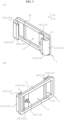
- Fig. 1(a) is a perspective view facing the front surface
- Fig. 1(b) is a perspective view facing the rear surface
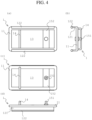
- Fig. 4 represents views of the attachment fixture 1 as viewed from various surfaces, in which Fig. 4(a) is a front view, Fig. 4(b) is a side view, Fig. 4(c) is a rear view, and Fig. 4(d) is a bottom view.
- the attachment fixture body 11 is a member provided to be a substantially rectangular flat plate with rounded corners as a whole, and is made of a metal member such as stainless steel or steel or a plastic member such as polyethylene.
- a width of the attachment fixture body 11 is provided to be at least larger than the width of the belt 3, and a horizontal length thereof is provided to be longer than the length of the physical information acquisition device 2. This enables proper attachment.
- the attachment portion 12 is a member provided to be integrally formed with the attachment fixture body 11, and the physical information acquisition device 2 is attached thereto.
- the attachment portion 12 includes a protrusion portion 121 provided to protrude from the attachment fixture body 11, and a fitting body 122 in which the physical information acquisition device 2 is fitted and attached at a tip portion of the protrusion portion 121.
- the attachment portion 12 is provided as a lateral sliding attachment portion 12A to which the physical information acquisition device 2 can be attached by sliding in a lateral direction. More specifically, the attachment portion 12 is formed along each end portion of an upper edge and a lower edge of the attachment fixture body 11 over substantially an entire region excluding rounded corner portions of the edges. Note that, the attachment portion 12 may be provided by dividing along the edges.
- the protrusion portion 121 is a member in a substantially flat plate shape provided to protrude from the surface of the attachment fixture body 11.
- a protrusion length of the protrusion portion is set to be at least longer than the distance from an emission and entrance surface 22 to an attached portion 23, which will be described later, so that the physical information acquisition device 2 does not interfere with the attachment fixture body 11.
- the length is provided to be substantially the same as the distance, so that the distance between the emission and entrance surface 22 and the user's body can be reduced as much as possible.
- the insertion portion is configured such that strength can be maintained by being formed as a member that bridges the upper edge and the lower edge of the attachment fixture body 11 provided as a frame body, and the belt 3 can be easily inserted by being provided to protrude in a back side direction and have a U-shape.
- a protruding height is preferably substantially the same as or slightly larger than twice a thickness of the belt 3.
- the adjustment portion 15 is a member capable of adjusting the length of the belt 3, and includes a hole insertion portion 151 for attachment to an attachment hole 32 of the belt 3 to be described later, and an adjustment plate body 152 for holding the hole insertion portion 151 at a predetermined position.
- the hole insertion portion 151 is provided substantially at the center of the adjustment plate body 152, and protrudes toward the back surface of the attachment fixture body 11.
- the hole insertion portion 151 includes a base portion attached to the adjustment plate body 152, a neck portion protruding from the base portion, and a head portion provided at an end portion of the neck portion.
- a protruding length of the neck portion is provided to be at least longer than twice the thickness of the belt 3.
- a diameter of the head portion is configured to be larger than the diameter of the neck portion, and the shape thereof is preferably a spherical or elliptical shape.
- the adjustment plate body 152 is a member in a flat plate shape provided to bridge the upper edge and the lower edge of the attachment fixture body 11, which is a frame body, and is provided such that the thickness thereof is substantially the same as the thickness of the attachment fixture body 11.
- the base portion of the hole insertion portion 151 is formed at the center portion, and is supported by being sandwiched between the back surface and the front surface.
- the insertion portion 14 and the adjustment portion 15 are provided to be out of the region of the transmission portion 13 that is the center of the frame body, and the transmission portion 13 occupies at least 1/2 of one surface of the attachment fixture body 11.
- the physical information acquisition device 2 is a device for acquiring physical information, and includes an acquisition device body 21 having a substantially rectangular parallelepiped shape, the emission and entrance surface 22 that emits and receives a predetermined measurement wave, and the attached portion 23 to which the attachment portion 12 is attached, and includes inside a control unit that controls and processes at least emission and reception of the measurement wave, a recording unit that records data, and a transmission unit that transmits and receives the recorded data to and from the outside.
- the acquisition device body 21 is a device in a substantially rectangular parallelepiped shape having a size enough to fit in the palm of a hand with a length of about 4 cm to 9 cm, a width of about 3 cm to 6 cm, and a width of about 0.5 cm to 3 cm, and is provided to be slightly larger than the width of the attachment fixture 1.
- a button for turning on a power source and a display unit capable of displaying information related to the physical information acquisition device 2 such as a remaining battery level are provided on a surface on which the attached portion 23 is not provided or a surface adjacent to a surface on which the attached portion 23 is provided.
- the emission and entrance surface 22 has a function of emitting a measurement wave (a standing wave of sound waves or radio waves (in particular millimeter waves, microwaves)) toward a predetermined angle and a function as a sensor that receives the measurement wave reflected on the user's body, and a portion where the measurement wave is actually exchanged is set as an emission and entrance position. As a result, the distance between the object to be measured and the emission and entrance surface 22 is grasped.
- a measurement wave a standing wave of sound waves or radio waves (in particular millimeter waves, microwaves)
- a measurement wave in order to sense a body part (in particular, the lung, intestinal tract, etc.) particularly in a state of being attached to the waist part of the user, a measurement wave can be emitted upward by about 30° to 70°.
- the function of receiving the measurement wave is preferably provided at at least two positions of the emission and entrance surface 22, and thus the movement of the lung can be stereoscopically grasped.
- the surface that outputs the measurement wave and the surface that emits the measurement wave may be different from each other, and a body temperature or the like may also be measured.
- the attached portion 23 is a hole portion that is provided near upper and lower end portions of the attachment fixture body 11 and penetrates from one end portion toward the other end portion in the lateral direction.
- the shape of the attached portion is provided corresponding to the shape of the attachment portion 12, so that it can be attached to the attachment portion 12 protruding from the attachment fixture body 11.
- the attached portions 23 are provided at intervals corresponding to two attachment portions 12, and with such a configuration, the acquisition device body 21 can be attached even when it is turned upside down.
- the physical information acquisition device 2 may be provided with a protrusion portion such as the attachment portion 12, and the attachment fixture 1 may be provided with a recess such as an attached portion.
- a U-shaped member such as the insertion portion 14 may be provided on one surface of the physical information acquisition device 2, and an attachment fixture or a belt may be penetrated and fixed inside the U-shaped member, preferably, two U-shaped members are provided to be parallel to each other, and the attachment fixture 1 and the like can be penetrated simultaneously in each portion to be easily attached.
- a vertical direction mentioned herein is not limited to a completely vertical direction, and may vary by about 5° depending on the attaching position of the user.
- the physical information acquisition device 2 is attached by sliding in the vertical direction on the front surface thereof, and the belt 3 wrapped around the waist part of the user is attached on the back surface thereof.
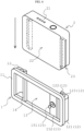
- Fig. 7 represents views of the attachment fixture 1 as viewed from various surfaces, in which Fig. 7(a) is a front view, Fig. 7(b) is a side view, Fig. 7(c) is a rear view, and Fig. 7(d) is a bottom view.
- the attachment fixture 1 includes the attachment fixture body 11 serving as the base portion of the attachment fixture 1, the attachment portion 12 to which the physical information acquisition device 2 is attached, the transmission portion 13 that transmits a measurement wave emitted from the physical information acquisition device 2, the insertion portion 14 that is attached as the mounting portion P by inserting the belt 3, and the adjustment portion 15 that can adjust the length of the belt 3.
- the attachment portion 12 includes the protrusion portion 121 provided to protrude from the attachment fixture body 11, the fitting body 122 in which the physical information acquisition device 2 is fitted at the tip portion of the protrusion portion 121, and a parallel piece 123 that connects the tip portion of the protrusion portion 121 and the fitting body 122.
- the attachment portion 12 in the present embodiment is provided as a vertical sliding attachment portion 12B to which the physical information acquisition device 2 can be attached by sliding in a vertical direction. More specifically, the attachment portion 12 is formed along the end portions of two side surface edges of the attachment fixture body 11 over substantially the entire region excluding rounded corner portions of the edge. Note that, the attachment portion 12 may be provided by dividing along the edges.
- the protrusion portion 121 in the present embodiment is provided to protrude longer by at least the thickness of the adjustment plate body 152 (or the thickness of the belt body 31) than the distance from the emission and entrance surface 22 to the attached portion 23. Further, the thickness is at least 2 mm or more, and is preferably provided over the entire region from an outer end to an inner end of a frame side surface portion of the attachment fixture body 11.
- the fitting body 122 is integrally formed at the end portion of the parallel piece 123, and is provided such that the shape thereof can be fitted to the attached portion 23 and is a shape substantially the same as the shape of the attached portion 23, and is provided to have a portion at least wider than the width of the protrusion portion 121.
- the parallel piece 123 is a component that connects a protruding end of the protrusion portion 121 and the fitting body 122, and is a piece that extends from the protrusion portion 121 in a direction toward the center of the attachment fixture body 11. Preferably, it is provided to be parallel to the upper edge and the lower edge of the attachment fixture body 11.
- the insertion portion 14 is a portion used for attaching the belt 3, and is configured such that the belt 3 can be inserted inside the insertion portion.
- the insertion portion 14 is provided to bridge the upper edge and the lower edge of the attachment fixture body 11 on the same plane as the attachment fixture body 11, thereby increasing the strength of the attachment fixture body.
- the length of the insertion portion 14 is substantially the same as the length of the belt body 31.
- the attached portion 23 is a hole portion provided near both side surface end portions of the attachment fixture body 11 and provided from the lower end portion toward the upper end portion in the vertical direction.
- the attached portion 23 is provided to be inserted into and attachable to the fitting body 122 and the parallel piece 123 and to have a shape corresponding to these components.
- the friction portion 162 is provided with a plurality of irregularities on a surface in contact with the attachment fixture body 11, and holds the attachment fixture body 11 by sandwiching the clothing on the surface.
- a method of attaching the attachment fixture 1 according to the present embodiment to the user's clothing is as follows.
- the user inserts the upper end of his/her clothing such as trousers, a skirt, or a belt, between the lower end of the clip body 161 and the attachment fixture body 11. As a result, the user can attach the attachment fixture 1 to the waist part.
- his/her clothing such as trousers, a skirt, or a belt
- the emission and entrance position of the emission and entrance surface 22 overlaps the position of the transmission portion 13, and the portion can be fixed at the waist part, so that the user can appropriately mount the physical information acquisition device 2 that senses the body.
- the clip portion can also be mounted through the belt 3. It is more preferable because the handling performance is improved, and in addition to the holding force by the clip portion 16, a holding force is generated by being attached to the belt 3.
- the attachment fixture 1 since the attachment fixture 1 is separated into a plurality of pieces or has a configuration that can be separated, the plurality of attachment fixtures is collectively referred to as an attachment fixture body Q.
- This attachment fixture body Q is in the same position as the attachment fixture body 11 in each of the previous embodiments.
- the attachment fixture 1 includes a first attachment fixture 18 and a second attachment fixture 19 as the attachment fixture body Q that functions as a body of the attachment fixture.
- Each attachment fixture 1 includes an attachment portion for attaching the physical information acquisition device 2 and the mounting portion P that is mounted to the waist part of the user, respectively.
- the attachment fixture 1 is made of a metal member such as stainless steel or steel, or a plastic member such as polyethylene.
- the width of the attachment fixture body Q is provided to be at least larger than the width of the belt 3, and may be provided to be curved toward the back surface in consideration of being mounted to the waist part of the user.
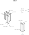
- the first attachment fixture 18 includes a body portion having a prismatic shape, a first attachment portion 181 for attaching one surface of the physical information acquisition device 2, and a first insertion portion 182 for passing through the belt 3.
- the first attachment portion 181 is provided such that the physical information acquisition device 2 can be attached by sliding it in the vertical direction. More specifically, the first attachment fixture 18 is formed from an upper end to a lower end of the first attachment fixture 18. Furthermore, a protrusion piece A1 that is provided to protrude from the first attachment fixture 18, and a fitting piece A2 in which the physical information acquisition device 2 is fitted at the tip portion of the protrusion piece A1 are included.
- the protrusion piece A1 is an edge provided to protrude from the first attachment fixture 18 by 3 mm to 10 mm, and is provided to be parallel to the belt 3 when appropriately attached.
- the thickness thereof is at least 2 mm or more, and is preferably provided over the entire region from the upper end to the lower end of the attachment fixture body Q.
- the fitting piece A2 is a component provided at the tip of the protrusion piece A1.
- the shape thereof is provided to be substantially the same as the shape of the attached portion 23 to be described later, so that it can be fitted with the attached portion 23, and is provided to have a portion at least wider than the width of the protrusion piece A1.
- the fitting piece A2 is a cylindrical member having an outer diameter larger than the width of the attached portion 23, but the shape is not limited thereto, and for example, it may be formed in a prismatic shape in which a corner portion is attached to the tip of the protrusion piece A1. Further, by making the size and shape of the fitting pieces A2 facing each other different, the emission and entrance surface 22 to be described later may always face the body.
- the first insertion portion 182 is a portion that is integrally molded with the first attachment fixture 18, through which the belt 3 is inserted, and an inserted portion is provided to have a rectangular parallelepiped shape having an opening in a substantially rectangular shape.
- the size of the opening is provided such that the height is at least larger than the width of the belt 3 and the width is at least larger than the thickness of the belt 3.
- the second attachment fixture 19 includes a second attachment portion 191 for attaching one surface of the physical information acquisition device 2, a second insertion portion 192 for passing through the belt 3, and the adjustment portion 15 for adjusting the length of the belt 3.
- the structure of the second attachment portion 191 is substantially the same as the structure of the first attachment portion 181, but the width of the opening is provided to be at least larger than twice the thickness of the belt 3, and the second attachment portion is provided to be bilaterally symmetrical with the first attachment portion so as to face each other when attached to the belt 3.
- the second insertion portion 192 has substantially the same structure as the first insertion portion 182, but is provided integrally with an adjustment portion body 141.
- the transmission portion 13 is a gap portion between the first attachment fixture 18 and the second attachment fixture 19. As a result, when the mounting portion P is not mounted and the physical information acquisition device 2 is attached to the attachment portion, the emission and entrance surface is exposed.
- each of the attachment fixtures 1 may be provided to be connectable to each other by a member that transmits a measurement wave.
- the transmission portion 13 transmits a measurement wave such as a sound wave or a radio wave emitted from the emission and entrance surface 22, or a measurement wave such as a sound wave or a radio wave reflected and returned to the emission and entrance surface 22.
- any configuration may be used as long as the measurement wave can be transmitted, for example, in a case where the measurement wave is a sound wave such as a Doppler wave, a mesh-like fiber member may be used, and in a case where the measurement wave is a radio wave such as a millimeter wave or a microwave, any member such as plastic or wood may be used as long as a member that shields the radio wave such as metal or liquid is not used.
- the attached portion 23 is a non-penetrating hole portion provided from the lower end portion toward the upper end portion of the attachment fixture body Q.
- the shape of the hole portion is provided to be substantially the same or slightly larger than the shape corresponding to the shape of each attachment portion, so that the hole portion can be attached to each attachment portion protruding from the attachment fixture body Q.
- the fitting piece A2 since the fitting piece A2 is provided, the movement in the direction of falling off can be restricted and fixed. Further, by not penetrating, falling off due to gravity can be prevented.
- the belt 3 is a belt-shaped member to be mounted to the waist part of the user, and includes a belt body 31 that is a body portion of the belt, and the attachment hole 32 that is a hole portion for penetrating the adjustment portion 15.
- the belt body 31 is a belt-shaped member made of leather or synthetic resin, and has a length that can be wrapped around the user's waist.
- the end portions of the belt body 31 will be described as one end portion 31A and the other end portion 31B.
- the fitting piece A2 is a component provided at the tip of the protrusion piece A1.
- the shape thereof is provided to be substantially the same as the shape of the attached portion 23 to be described later, so that it can be fitted with the attached portion 23, and is provided to have a portion at least wider than the width of the protrusion piece A1.
- the attached portion 23 is a hole portion provided from one end portion toward the other end portion in the lateral direction in the attachment fixture body Q.
- the shape thereof is provided corresponding to the shapes of the first attachment fixture 18 and the second attachment fixture 19 so that it can be attached to the first attachment fixture 18 and the second attachment fixture 19.
- a depth of the hole is at least larger than the width of the fitting piece A2, and is preferably twice or more of the width. Further, it may penetrate the physical information acquisition device 2.
- the emission and entrance surface faces the user's body.
- the attached portion 23 is provided at intervals corresponding to a plurality of attachment portions provided in the attachment fixture body Q, thereby improving the holding performance.
- a member that can be gripped by the user may be provided on an upper surface of the protrusion A32.
- attachment fixture 1 according to a seventh embodiment of the present invention will be described in detail with reference to Fig. 15 .
- the same components as those of each embodiment described above are denoted by the same reference numerals, and the description thereof will be omitted.
- the attachment fixture 1 of the present embodiment is provided with a mechanism that attaches the physical information acquisition device 2 on the front surface thereof and attaches the physical information acquisition device 2 on the back surface thereof at the waist part of the user.
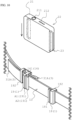
- the attachment fixture 1 includes the attachment fixture body Q serving as the base portion of the attachment fixture 1, the first attachment portion 181 and the second attachment portion 191 to which the physical information acquisition device 2 is attached toward the user's body, the transmission portion 13 that transmits a measurement wave emitted from the physical information acquisition device 2, and the clip portion 16 that is attached by sandwiching the user's clothing (for example, trousers or a skirt) as the mounting portion P.
- the attachment fixture body Q serving as the base portion of the attachment fixture 1, the first attachment portion 181 and the second attachment portion 191 to which the physical information acquisition device 2 is attached toward the user's body
- the transmission portion 13 that transmits a measurement wave emitted from the physical information acquisition device 2
- the clip portion 16 that is attached by sandwiching the user's clothing (for example, trousers or a skirt) as the mounting portion P.
- the clip portion 16 includes the clip body 161 that sandwiches the user's clothing with each of the attachment fixtures 1, and the friction portion 162 that acts as an anti-slip portion between the clothing and the attachment fixture body Q.
- the clip body 161 is a plate-shaped member provided to extend to the edge of the lower end with the edge of the upper end of each of the attachment fixtures 1 as a base portion.
- the clip body 161 is provided at a position overlapping at least with each of the attachment fixtures 1 when viewed from the back, and is sandwiched on the user's clothing with each of the attachment fixtures 1.
- the clip body 161 is configured to protrude outward at the base portion thereof, to approach the body portion of each of the attachment fixtures 1 as it moves downward, and to be substantially in contact with the body portion at lower end portion, thereby enabling firm attachment.
- the friction portion 162 is provided with a plurality of irregularities on a surface in contact with the attachment fixture body Q, and holds the attachment fixture body Q by sandwiching clothing on the surface.
- the method of generating friction is not limited thereto, and a structure in which a rubber plate or the like is provided may be used.
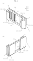
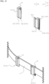
- Fig. 16(a) illustrates a state of the attachment fixture 1 before being attached
- Fig. 16(b) illustrates the attachment fixture 1 attached to the physical information acquisition device 2.
- the attachment fixture 1 of the present embodiment includes the first attachment fixture 18 and the second attachment fixture 19.
- Each attachment fixture 1 includes an attachment portion for attaching the physical information acquisition device 2 and the mounting portion P that is mounted to the waist part of the user, respectively.
- the first attachment fixture 18 includes the first attachment portion 181 in a ring shape and the first insertion portion 182 through which the belt 3 is inserted and that maintains the shape of the first attachment portion 181.
- the first attachment portion 181 is a portion formed into a ring shape by causing the end portion of the belt 3 to pass through the first insertion portion 182 twice.
- the diameter of the ring is preferably 5 mm to 20 mm.
- first attachment portion 181 may be a ring-shaped member provided by attaching to first insertion portion 182.
- the first insertion portion 182 is a loop member having a substantially rectangular parallelepiped shape through which the belt 3 is inserted, and a hole provided inside is at least larger than the width of the belt, and the width is larger than twice the thickness of the belt.
- the second attachment fixture 19 includes an insertion portion B1 that functions as the second attachment portion 191 and is inserted into the attached portion 23 to be described later, and a connection portion B3 that has a detachable portion B2 for preventing unintentional removal and is connected to an end portion of the belt 3 as the mounting portion P to be mounted on the belt 3.
- the insertion portion B1 is a substantially rectangular parallelepiped member having such rigidity that the insertion portion B1 cannot be bent by human force, and is provided to have substantially the same thickness as the attached portion 23 to be described later and a height smaller than that of the attached portion 23.
- the detachable portion B2 is an elastic member provided to extend from both ends of the insertion portion B1, and a cut that generates a gap with the insertion portion B1 is provided from the direction of the connection portion B3.
- the width of the cut is provided to be at least larger than the height of a locking body B5 to be described later.
- an interval between the detachable portions B2 is substantially the same as the height of an insertion port B4 to be described later, but is provided to be at least larger than the interval between locking bodies B5 to be described later, and when the detachable portion B2 is pushed inward, it can be deformed larger than the height of the locking body B5.
- connection portion B3 is a hole portion that is fixed so as not to be removed in a state where the end portion of the belt 3 is inserted inside.
- a control button 211 of the physical information acquisition device 2 is provided such that it can be pressed against a surface facing the emission and entrance surface 22, and the attached portion 23 corresponding to each of the first attachment fixture 18 and the second attachment fixture 19 is provided.
- the emission and entrance surface 22 is exposed in a state of not being mounted, and the emission and entrance surface 22 is attached to face the user's body.
- the attached portion 23 corresponding to the first attachment fixture 18 is a hole portion that is provided near the end portion of the physical information acquisition device 2 and penetrates the surface having the emission and entrance surface 22, and is provided to have a width at least larger than the thickness of the belt 3 and a height larger than the height of the belt 3.
- the attached portion 23 corresponding to the second attachment fixture 19 includes the insertion port B4 through which the insertion portion B1 is inserted and attached, the locking body B5 that is provided on an inner peripheral surface of the insertion port B4 and cooperates with the detachable portion B2 to prevent the attachment fixture from falling off, and a pressing portion 17 that presses the detachable portion B2 in an attached state to remove the second attachment fixture 19.
- the pressing portion 17 may be provided on the side of the belt 3, that is, the insertion portion B1.
- the length of the insertion portion B1 in an insertion direction is longer than the depth of the insertion port B4, and when the insertion portion B1 is inserted into the insertion port B4 according to Fig. 16(b) , the side of the belt 3 of the insertion portion B1 protrudes.
- This protruding length is slightly larger than the size of the pressing portion 17, and is preferably about 10% more to twice the length of the pressing portion 17 in the insertion direction.
- the position of the pressing portion 17 may be provided on the surface in a thickness direction of the belt 3, the surface on the side of the emission and entrance surface 22, or the surface facing the emission and entrance surface, and the shape is limited to a circular shape, and may be provided in an oval shape, a rectangular shape with rounded corners, or the like.
- the physical information acquisition device 2 may be provided with illumination.
- This illumination is preferably one with a diameter of 5 mm or less, such as an LED, which indicates the operation of the physical information acquisition device 2 and the remaining battery level.
Landscapes
- Health & Medical Sciences (AREA)
- Life Sciences & Earth Sciences (AREA)
- General Health & Medical Sciences (AREA)
- Public Health (AREA)
- Pathology (AREA)
- Engineering & Computer Science (AREA)
- Biomedical Technology (AREA)
- Heart & Thoracic Surgery (AREA)
- Medical Informatics (AREA)
- Molecular Biology (AREA)
- Surgery (AREA)
- Veterinary Medicine (AREA)
- Biophysics (AREA)
- Physics & Mathematics (AREA)
- Animal Behavior & Ethology (AREA)
- Physiology (AREA)
- Dentistry (AREA)
- Oral & Maxillofacial Surgery (AREA)
- Nuclear Medicine, Radiotherapy & Molecular Imaging (AREA)
- Radiology & Medical Imaging (AREA)
- Purses, Travelling Bags, Baskets, Or Suitcases (AREA)
- Measurement Of The Respiration, Hearing Ability, Form, And Blood Characteristics Of Living Organisms (AREA)
- Measuring Pulse, Heart Rate, Blood Pressure Or Blood Flow (AREA)
- Orthopedics, Nursing, And Contraception (AREA)
Applications Claiming Priority (5)
| Application Number | Priority Date | Filing Date | Title |
|---|---|---|---|
| JP2022086043A JP7208687B1 (ja) | 2022-05-26 | 2022-05-26 | 取付具 |
| JP2022086045 | 2022-05-26 | ||
| JP2022119550A JP7232557B1 (ja) | 2022-05-26 | 2022-07-27 | 取付具 |
| JP2022171537A JP7232558B1 (ja) | 2022-05-26 | 2022-10-26 | 取付具の構造及び身体情報取得装置の取付方法 |
| PCT/JP2023/018126 WO2023228797A1 (fr) | 2022-05-26 | 2023-05-15 | Outil de fixation |
Publications (2)
| Publication Number | Publication Date |
|---|---|
| EP4534007A1 true EP4534007A1 (fr) | 2025-04-09 |
| EP4534007A4 EP4534007A4 (fr) | 2026-04-01 |
Family
ID=88919202
Family Applications (1)
| Application Number | Title | Priority Date | Filing Date |
|---|---|---|---|
| EP23811671.9A Pending EP4534007A4 (fr) | 2022-05-26 | 2023-05-15 | Outil de fixation |
Country Status (6)
| Country | Link |
|---|---|
| US (2) | US20240285235A1 (fr) |
| EP (1) | EP4534007A4 (fr) |
| KR (2) | KR20240013242A (fr) |
| CN (1) | CN117642118A (fr) |
| CA (1) | CA3257531A1 (fr) |
| WO (1) | WO2023228797A1 (fr) |
Families Citing this family (1)
| Publication number | Priority date | Publication date | Assignee | Title |
|---|---|---|---|---|
| WO2026004468A1 (fr) * | 2024-06-26 | 2026-01-02 | 株式会社D.O.N | Dispositif de génération d'ondes électromagnétiques |
Family Cites Families (22)
| Publication number | Priority date | Publication date | Assignee | Title |
|---|---|---|---|---|
| US4473949A (en) * | 1982-09-02 | 1984-10-02 | Schechtman Jay C | Numerical display belt |
| JPH09299492A (ja) | 1996-05-16 | 1997-11-25 | Masayuki Matsunaga | ベルト及びベルトの移動体の保持方法 |
| JP3076482U (ja) | 2000-09-21 | 2001-04-06 | 和廣 入江 | 携帯型拭き取り器 |
| CA2617621A1 (fr) | 2005-08-01 | 2007-02-08 | Carolyn M. Merkel | Dispositif d'entrainement physique a porter et dispositif d'entrainement physique interchangeable avec plusieurs articles a porter |
| US7607243B2 (en) * | 2006-05-03 | 2009-10-27 | Nike, Inc. | Athletic or other performance sensing systems |
| US7839625B2 (en) * | 2006-09-04 | 2010-11-23 | Intermec Ip Corp. | Tool belt with smart cell technology |
| JP2009078123A (ja) | 2007-09-07 | 2009-04-16 | Morito Co Ltd | 取付部品と取付対象物との連結方法 |
| US9282897B2 (en) * | 2012-02-13 | 2016-03-15 | MedHab, LLC | Belt-mounted movement sensor system |
| CN105530858B (zh) | 2013-09-16 | 2022-06-07 | 皇家飞利浦有限公司 | 用于估计人员的心血管健康的系统和方法 |
| US10292654B2 (en) | 2013-12-16 | 2019-05-21 | Johnson & Johnson Consumer Inc. | Biomedical device, systems and methods having conductive elements |
| US9380855B2 (en) | 2014-12-08 | 2016-07-05 | Intel Corporation | System and method for generating and using a wearable device profile |
| US20180014741A1 (en) | 2015-01-26 | 2018-01-18 | Chang-An Chou | Wearable physiological monitoring device |
| US20160324442A1 (en) * | 2015-05-08 | 2016-11-10 | Proteus Digital Health, Inc. | Loose wearable receiver systems |
| GB201513208D0 (en) * | 2015-07-27 | 2015-09-09 | Univ Central Lancashire | Methods and apparatuses for estimating bladder status |
| WO2017034141A1 (fr) * | 2015-08-24 | 2017-03-02 | Samsung Electronics Co., Ltd. | Procédé et système de détermination de longueur d'objet à l'aide de dispositifs électroniques |
| KR101795215B1 (ko) * | 2016-02-25 | 2017-11-08 | 김주희 | 스마트 벨트 |
| JP2018201581A (ja) | 2017-05-30 | 2018-12-27 | Joyson Safety Systems Japan株式会社 | バックル |
| JP2019058573A (ja) * | 2017-09-28 | 2019-04-18 | 国立大学法人旭川医科大学 | 生体信号取得装置、および生体信号取得用装着具 |
| WO2019094820A1 (fr) * | 2017-11-10 | 2019-05-16 | Gluco-Z GmbH | Système et procédé de surveillance non invasive, continue en temps réel du glucose sanguin |
| WO2020017358A1 (fr) | 2018-07-20 | 2020-01-23 | ソニー株式会社 | Outil pouvant être porté |
| KR102096341B1 (ko) | 2018-08-09 | 2020-04-02 | 기주현 | 폐전지로부터 원료를 회수하는 방법 |
| US11412797B2 (en) * | 2019-09-30 | 2022-08-16 | Sunil Daniel | System and method for waist circumference measurement and feedback for optimal placement of a smart belt |
-
2023
- 2023-05-15 EP EP23811671.9A patent/EP4534007A4/fr active Pending
- 2023-05-15 CA CA3257531A patent/CA3257531A1/fr active Pending
- 2023-05-15 KR KR1020237045125A patent/KR20240013242A/ko active Pending
- 2023-05-15 US US18/574,521 patent/US20240285235A1/en active Pending
- 2023-05-15 CN CN202380012572.9A patent/CN117642118A/zh active Pending
- 2023-05-15 KR KR1020267005200A patent/KR20260045821A/ko active Pending
- 2023-05-15 WO PCT/JP2023/018126 patent/WO2023228797A1/fr not_active Ceased
-
2025
- 2025-06-26 US US19/251,344 patent/US20250318782A1/en active Pending
Also Published As
| Publication number | Publication date |
|---|---|
| CA3257531A1 (fr) | 2025-04-15 |
| KR20260045821A (ko) | 2026-04-03 |
| US20250318782A1 (en) | 2025-10-16 |
| EP4534007A4 (fr) | 2026-04-01 |
| US20240285235A1 (en) | 2024-08-29 |
| WO2023228797A1 (fr) | 2023-11-30 |
| KR20240013242A (ko) | 2024-01-30 |
| CN117642118A (zh) | 2024-03-01 |
Similar Documents
| Publication | Publication Date | Title |
|---|---|---|
| US20250318782A1 (en) | Attachment fixture | |
| EP3050503B1 (fr) | Capteurs de photopléthysmographie | |
| CA2897862C (fr) | Procedes, dispositifs et systemes pour la photoplethysmographie au niveau de la columelle nasale | |
| US11911155B2 (en) | Monitoring apparatus and method | |
| US8025539B2 (en) | Connector for biometric belt | |
| JP2015534495A (ja) | 監視デバイス | |
| US20150038810A1 (en) | Sensors for photoplethysmography at the ophthalmic artery region | |
| US9770198B2 (en) | Sensor and fastener | |
| US20160022213A1 (en) | Clip adaptor for an activity monitor device and other devices | |
| JP2023540735A (ja) | 電子ユニットを連続分析物監視デバイスのベースユニットに結合することを可能にする方法および装置 | |
| EP3892188A1 (fr) | Dispositif de mesure d'informations biologiques | |
| US11957485B2 (en) | Hat and monitoring system | |
| US20110283540A1 (en) | Back shaving device | |
| JP7232557B1 (ja) | 取付具 | |
| JP7208687B1 (ja) | 取付具 | |
| JP2020018783A (ja) | 電極ユニットおよび衣服 | |
| WO2019195945A1 (fr) | Dispositif et procédé de surveillance physiologique | |
| CN120456860A (zh) | 用于医疗装置的适配器的设备、系统和方法 | |
| CN215017478U (zh) | 血氧探头固定器 | |
| CN210644031U (zh) | 腕式一体血氧检测装置 | |
| KR101236561B1 (ko) | 벨트 체결 장치 및 이를 이용한 심박 측정 벨트 | |
| EP4124295A1 (fr) | Appareil de surveillance et procédé associé | |
| CN120227016A (zh) | 用于体征监测的探头结构 | |
| CN220458761U (zh) | 一种绑带及可穿戴设备 | |
| CN211434505U (zh) | 一种动脉留置针固定装置 |
Legal Events
| Date | Code | Title | Description |
|---|---|---|---|
| STAA | Information on the status of an ep patent application or granted ep patent |
Free format text: STATUS: THE INTERNATIONAL PUBLICATION HAS BEEN MADE |
|
| PUAI | Public reference made under article 153(3) epc to a published international application that has entered the european phase |
Free format text: ORIGINAL CODE: 0009012 |
|
| STAA | Information on the status of an ep patent application or granted ep patent |
Free format text: STATUS: REQUEST FOR EXAMINATION WAS MADE |
|
| 17P | Request for examination filed |
Effective date: 20241111 |
|
| AK | Designated contracting states |
Kind code of ref document: A1 Designated state(s): AL AT BE BG CH CY CZ DE DK EE ES FI FR GB GR HR HU IE IS IT LI LT LU LV MC ME MK MT NL NO PL PT RO RS SE SI SK SM TR |
|
| DAV | Request for validation of the european patent (deleted) | ||
| DAX | Request for extension of the european patent (deleted) | ||
| A4 | Supplementary search report drawn up and despatched |
Effective date: 20260304 |
|
| RIC1 | Information provided on ipc code assigned before grant |
Ipc: A61B 5/11 20060101AFI20260226BHEP Ipc: A44B 99/00 20100101ALI20260226BHEP Ipc: A61B 5/113 20060101ALI20260226BHEP Ipc: A61B 5/00 20060101ALI20260226BHEP Ipc: A61B 5/0507 20210101ALI20260226BHEP |