EP4534029A2 - Universales handstück für einen elektrischen behandlungsapplikator - Google Patents
Universales handstück für einen elektrischen behandlungsapplikator Download PDFInfo
- Publication number
- EP4534029A2 EP4534029A2 EP25158915.6A EP25158915A EP4534029A2 EP 4534029 A2 EP4534029 A2 EP 4534029A2 EP 25158915 A EP25158915 A EP 25158915A EP 4534029 A2 EP4534029 A2 EP 4534029A2
- Authority
- EP
- European Patent Office
- Prior art keywords
- impedance matching
- handle
- electrode tip
- tip
- selector
- Prior art date
- Legal status (The legal status is an assumption and is not a legal conclusion. Google has not performed a legal analysis and makes no representation as to the accuracy of the status listed.)
- Pending
Links
Images








Classifications
-
- A—HUMAN NECESSITIES
- A61—MEDICAL OR VETERINARY SCIENCE; HYGIENE
- A61B—DIAGNOSIS; SURGERY; IDENTIFICATION
- A61B18/00—Surgical instruments, devices or methods for transferring non-mechanical forms of energy to or from the body
- A61B18/04—Surgical instruments, devices or methods for transferring non-mechanical forms of energy to or from the body by heating
- A61B18/12—Surgical instruments, devices or methods for transferring non-mechanical forms of energy to or from the body by heating by passing a current through the tissue to be heated, e.g. high-frequency current
- A61B18/14—Probes or electrodes therefor
- A61B18/1402—Probes for open surgery
-
- A—HUMAN NECESSITIES
- A61—MEDICAL OR VETERINARY SCIENCE; HYGIENE
- A61B—DIAGNOSIS; SURGERY; IDENTIFICATION
- A61B18/00—Surgical instruments, devices or methods for transferring non-mechanical forms of energy to or from the body
- A61B18/04—Surgical instruments, devices or methods for transferring non-mechanical forms of energy to or from the body by heating
- A61B18/12—Surgical instruments, devices or methods for transferring non-mechanical forms of energy to or from the body by heating by passing a current through the tissue to be heated, e.g. high-frequency current
- A61B18/1206—Generators therefor
- A61B18/1233—Generators therefor with circuits for assuring patient safety
-
- A—HUMAN NECESSITIES
- A61—MEDICAL OR VETERINARY SCIENCE; HYGIENE
- A61B—DIAGNOSIS; SURGERY; IDENTIFICATION
- A61B18/00—Surgical instruments, devices or methods for transferring non-mechanical forms of energy to or from the body
- A61B18/04—Surgical instruments, devices or methods for transferring non-mechanical forms of energy to or from the body by heating
- A61B18/12—Surgical instruments, devices or methods for transferring non-mechanical forms of energy to or from the body by heating by passing a current through the tissue to be heated, e.g. high-frequency current
- A61B18/1206—Generators therefor
-
- A—HUMAN NECESSITIES
- A61—MEDICAL OR VETERINARY SCIENCE; HYGIENE
- A61B—DIAGNOSIS; SURGERY; IDENTIFICATION
- A61B18/00—Surgical instruments, devices or methods for transferring non-mechanical forms of energy to or from the body
- A61B2018/00053—Mechanical features of the instrument of device
- A61B2018/00172—Connectors and adapters therefor
- A61B2018/00178—Electrical connectors
-
- A—HUMAN NECESSITIES
- A61—MEDICAL OR VETERINARY SCIENCE; HYGIENE
- A61B—DIAGNOSIS; SURGERY; IDENTIFICATION
- A61B18/00—Surgical instruments, devices or methods for transferring non-mechanical forms of energy to or from the body
- A61B2018/00636—Sensing and controlling the application of energy
- A61B2018/00696—Controlled or regulated parameters
- A61B2018/00755—Resistance or impedance
-
- A—HUMAN NECESSITIES
- A61—MEDICAL OR VETERINARY SCIENCE; HYGIENE
- A61B—DIAGNOSIS; SURGERY; IDENTIFICATION
- A61B18/00—Surgical instruments, devices or methods for transferring non-mechanical forms of energy to or from the body
- A61B18/04—Surgical instruments, devices or methods for transferring non-mechanical forms of energy to or from the body by heating
- A61B18/12—Surgical instruments, devices or methods for transferring non-mechanical forms of energy to or from the body by heating by passing a current through the tissue to be heated, e.g. high-frequency current
- A61B18/14—Probes or electrodes therefor
- A61B2018/1405—Electrodes having a specific shape
- A61B2018/1425—Needle
-
- A—HUMAN NECESSITIES
- A61—MEDICAL OR VETERINARY SCIENCE; HYGIENE
- A61B—DIAGNOSIS; SURGERY; IDENTIFICATION
- A61B18/00—Surgical instruments, devices or methods for transferring non-mechanical forms of energy to or from the body
- A61B18/04—Surgical instruments, devices or methods for transferring non-mechanical forms of energy to or from the body by heating
- A61B18/12—Surgical instruments, devices or methods for transferring non-mechanical forms of energy to or from the body by heating by passing a current through the tissue to be heated, e.g. high-frequency current
- A61B18/14—Probes or electrodes therefor
- A61B2018/1467—Probes or electrodes therefor using more than two electrodes on a single probe
-
- A—HUMAN NECESSITIES
- A61—MEDICAL OR VETERINARY SCIENCE; HYGIENE
- A61B—DIAGNOSIS; SURGERY; IDENTIFICATION
- A61B18/00—Surgical instruments, devices or methods for transferring non-mechanical forms of energy to or from the body
- A61B18/04—Surgical instruments, devices or methods for transferring non-mechanical forms of energy to or from the body by heating
- A61B18/12—Surgical instruments, devices or methods for transferring non-mechanical forms of energy to or from the body by heating by passing a current through the tissue to be heated, e.g. high-frequency current
- A61B18/14—Probes or electrodes therefor
- A61B2018/1495—Electrodes being detachable from a support structure
Definitions
- the apparatuses described herein may be used with a pulse generator and may be provided as a part of the pulse generator systems.
- these apparatuses may include an applicator comprising a handle (also referred to as a handpiece or an applicator handle) that is configured to removably couple with a variety of different treatment tips (e.g., electrode tips), so that the applicator may deliver energy generated by the pulse generator through a treatment tip into the tissue.
- a handle also referred to as a handpiece or an applicator handle
- treatment tips e.g., electrode tips
- these handles may include an interface for removably engaging the electrode tip, and a plurality of different impedance matching circuits.
- These impedance matching circuits may include one or more resistors and may be configured in the circuit in parallel to the electrodes of the electrode tip and the pulse generator.
- An impedance matching circuit may include one or more combinations of the impedance matching element; different impedance matching circuits may share impedance matching elements (e.g., resistors, inductors, capacitors, etc.).
- impedance matching circuits may share components that may be combined in differently to create different impedance matching circuits by forming different combinations of overlapping components.
- the handle may also include an impedance matching selector that is part of the interface between the handle and the treatment tip.
- the impedance matching selector may receive the encoding shape connector or encoding shape connection from the electrode tip and may couple or configure the appropriate one or more impedance matching circuits in the handle to the electrode tip based on the encoding shape connection.
- the encoding shape connection may be all or part of the electrical connector(s) of the electrode tip that are in electrical communication with the one or more electrodes on the electrode tip.
- the encoding shape connection may be formed, as least in part, by the plurality of electrode tip connectors on the treatment tip.
- the encoding shape connection of the electrode tip includes a plurality of pins extending from the electrode tip that are conductive and also form the electrode tip electrical connector(s).
- the plurality of impedance matching circuits may be housed within the handle.
- a handle housing may enclose all or part of the plurality of impedance matching circuits.
- the plurality of impedance matching circuits may each include a pair of connectors, referred to herein as internal connectors, that may form a part of the impedance matching selector and may selectively couple each impedance matching circuit to the electrode tip electrical connectors in order to provide impedance matching.
- the plurality of impedance matching circuits may be arranged so that the impedance matching circuits may each be connected in parallel with one another.
- an applicator may include: a removable electrode tip, the electrode tip comprising a plurality of electrodes, and a plurality of electrode tip connectors in communication with the plurality of electrodes; and a handle, the handle comprising a plurality of impedance matching circuits (which may be configured as dedicated circuits or may overlap and share components between difference circuits); a plurality of handle connectors configured to engage with the plurality of electrode tip connectors so that the plurality of electrodes of the electrode tip are in electrical communication with the pulse generator; and an impedance matching selector configured to selectively couple the plurality of electrode tip electro-mechanical connectors with one or more of the impedance matching circuits of the plurality of impedance matching circuits based on an encoding shape connection with the electrode tip.
- the electrode tip may be configured to be removably coupled to a distal end of the handle. Any of these applicators or instruments may include additional electrode tips, such as a second removable electrode tip having an encoding shape connection that is different from the encoding shape connection of the removable electrode tip (e.g., the first removable electrode tip).
- the impedance matching circuits may share circuit components (e.g., resistors, capacitors, inductors, etc.) between some (or all) of the separate impedance matching circuits described herein.
- circuit components e.g., resistors, capacitors, inductors, etc.
- the handle (or any other appropriate portion of the apparatus, such as the tip and/or pulse generator) may include a plurality of impedance matching circuits, these circuits may be assembled or connected in contact with the one or more tips; it is understood that these incomplete or unconnected impedance matching circuits, which are completed by connection of a particular tip type to the handle, are still referred to herein as impedance matching circuits.
- the minimum clearance distance may be proportionally smaller (e.g., where the pulses delivered have a peak of about 10 kV, the minimum clearance distance may be 10 mm or greater, 15 mm or greater, etc.).
- a pulse generator system may include any of the electrode tips described herein ("electrodes"), a user control input (e.g., footswitch) and user interface (display, monitor, speaker, etc.).
- the user control input and interface may be connected to the control circuitry within a housing that holds the electronic components.
- the electrode tips may be connected to the applicator (e.g., handle) and the handle may be connected to the other pulse generator circuitry/electronic components through a high voltage connector 115, as mentioned above. Examples of such high voltage connectors are described in the co-pending and co-owned International patent application PCT/US2017/052340 .
- the user may input or select treatment parameters, such as a number of pulses, amplitude, pulse duration, and frequency information, via one or more input devices, such as a numeric keypad, touch screen, mice, track pad, stylus, pen, speaker, etc.
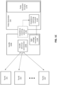
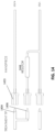
- first impedance-matching circuit which may include a combination of impedance matching circuit components ("A"), thus placing this first impedance matching circuit ("A") in parallel with the electrodes in the tip (not shown in FIG. 1B ) that are adapted to contact the tissue to be treated.
- A impedance matching circuit components
- a second impedance-matching circuit (B) which may be separate from circuit "A” or may include some or all of these components (e.g., connect in parallel and/or in series), in addition to additional components.
- the electrodes on the second tip 101'A may therefore be electrically connected in parallel with the impedance matching circuit ("B").
- the impedance matching selector 113B may connect to one or more of a plurality of impedance matching circuits 111B within the pulse generator so that the impedance matching selector may selectively engage one or more individual or combinations of the impedance matching circuit components, e.g., in parallel with the connection between the handle electrical connector(s) 105B and the pulse generator circuitry 117B, to adjust impedance matching of the electrode tip based on the way that the electrode tip engages with the handle and directly or indirectly with the impedance matching selector 113B.
- the electrode tip may engage with the handle, which may detect (either mechanically or electrically) an impedance setting specific to a particular tip.
- the impedance matching selector 113B may detect the impedance setting directly or indirectly.
- the impedance matching selector may include software or firmware for encoding (e.g., electrically encoding) the impedance setting corresponding to a particular tip and may transfer the encoded impedance setting to the impedance matching circuit 111B in the handle.
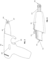
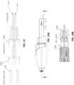
- FIGS. 2 illustrates one example of an applicator handle 200 as described herein.
- the reusable handle also referred to herein as an applicator handle or universal handle
- the electrode tip 201 in this example includes a plurality of penetrating (e.g., needle) electrodes 203.
- the electrode tip may include an insulating, distal-facing portion 207 that may be soft and/or compliant.
- the reusable handle 200 may include one or more controls 208, 208' that may be used to control the delivery of electrical energy through the electrodes.
- the second impedance matching circuit 509 as well as the first impedance matching circuit 507 are included in the electrical pathway between the tip electrode 505' and the pulse generator circuitry 515, as the impedance matching selector 513 has closed gates 551, 551', placing it in parallel with the tip electrodes of the tip 501', thereby setting the impedance matching circuit, as shown.
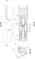
- Two or more electrode tip electrical connectors on the tip may engage with handle electrical connectors 625, 625' that are accessible through (and/or may be part of) the impedance matching selector, as shown in FIG. 6 .
- These connectors may be, for example, high-current/high power contacts (e.g., RADSOK high current connectors).
- the plunger 621 may travel, e.g., more than 10 mm (e.g., more than 15 mm, more than 19 mm, etc.) and may displace an internal set of connectors that may connect to the electrical pathway between the handle electrical connectors (that are coupled to the electrode tip electrical connectors) and the pulse generator circuitry.
- FIG. 7 shows a partially exploded view of the impedance matching selector of FIG. 6 .
- the outer housing 702 of the impedance matching selector encloses and provides a channel for the plunger 721.
- the plunger is coupled to a bias 725 (shown here as a spring, such as a spring having a preload of about 0.1 lb and a final load of about 1 lb) and is part of a sled 732.
- the sled also holds a set of internal electrical contacts 727, which in this example are a pair of jumper connects.
- the configuration of the internal connectors may also be set up so that the arrangement between internal connectors in the "open circuit" (not connected) configuration may include a significant air gap to prevent arcing and may be set some minimum creep distance apart (e.g., at least 10 mm, at least 15 mm, at least 20 mm, at least 25 mm, at least 30 mm, at least 35 mm, at least 40 mm, at least 45 mm, etc.).
- FIG. 8C shows a cut away view of an internal section through the impedance matching selector 813 when the plunger is not engaged and the internal set of connectors 827, 837 (which may be referred to herein as internal electrical contacts) are not engaged but are held apart by the bias (not shown in FIG. 8C ).
- the spacing 861 between the internal connectors 827, 837 is a minimum air gap distance.
- the minimum air gap distance is greater than 10 mm (e.g., approximately 14.3 mm).
- the minimum clearance distance 855 (shown in bold) is greater than a minimum clearance distance that avoids arcing; in FIG. 8C , the minimum clearance distance is at least twice the sum of the air gap 861 length.
- the second set of internal electrical contacts is statically held and is connected to the impedance matching circuit (e.g., impedance matching resistor 1144).
- the impedance matching circuit is coupled to the handle electrical connector 1166 for receiving the electrode tip electrical connectors, but the impedance matching circuit is open (unconnected) until the internal mechanical switch is closed by driving the plunger proximally, as described above, to close the air gap travel distance 1161 and connect the internal connector.
- the handle electrical connector 1166 is also attached to a wire (e.g., a high-voltage wire 1177) and/or a first impedance matching circuit that connects the handle electrical connector to the pulse generator.
- FIG. 11B shows a front view of the handle of FIG. 11A , showing the distal opening 1123.
- FIG. 14 illustrates another example of an impedance matching selector similar to that shown in FIG. 11A , above.
- This configuration includes three pins that may be keyed to form the encoding shape connection between the electrode tip and the pulse generator circuitry.
- the three (or more) pins may be the same length, rather than relying on pins of different length to make different connections with the internal connectors of the impedance matching selector. For example in FIG.
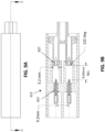
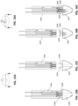
- FIGS. 15A-15C and 16A-16C show examples of tips and handles configured so that the impedance matching selector is based on the number, position and/or length of the pins (electrode pins or connectors) when the tip engages with the handle.
- the apparatus is similar to the one shown schematically in FIG. 14 .
- the pins extend from the proximal end of the electrode tip 1501 or 1601, and include a first pin 1504 or 1604, a second pin 1606 and (in some examples) a third pin 1508 or 1608.
- the first pin 1604 is electrically continuous with the second pin 1606.
- FIG. 17 schematically illustrates an example of a configuration in which the impedance matching selector includes a plurality of internal contacts, similar to that shown in FIG. 11A , but with cross-connected impedance matching circuits.
- the impedance matching selector includes a plurality of internal contacts, similar to that shown in FIG. 11A , but with cross-connected impedance matching circuits.
- FIG. 17 four internal connectors are shown.
- a first internal connector 1771 and a third internal connector 1773 may be configured as annular connectors, while a second internal connector 1775 and a fourth internal connector 1777a may be annular or not (e.g., shown as pins in FIG. 17 ).
- Each internal connector is connected to an impedance matching circuit and these circuits are cross-connected (e.g., the first and fourth connectors are connected, the second and third connectors are connected, etc.).
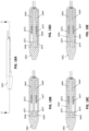
- FIGS. 18A-18G illustrate the use of an apparatus such as that shown schematically in FIGS. 17 .
- FIG. 18A shows a portion of a handle and a tip disconnected from each other
- FIG. 18F shows a portion of a handle and a tip connected to each other
- FIGS. 18B-18E illustrate different configuration for engage a tip to the handle to select the impedance matching to the particular tip configurations shown.
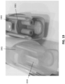
- FIG. 19 illustrates examples of electrode tips having different keying, with and without a displaceable member.
- the tip on the left (1901) includes a protrusion (e.g., a post or plunger 1919) that is configured to push and engage the impedance matching selector on the handle.
- electrode tip electrical conductors may make electrical contact with handle electrical connectors, which may be part of the impedance matching selector, or separate.
- the tip on the right (1903) does not include a displaceable member, such as protrusion and is flat in this region 1921.
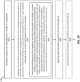
- Coupling may include engaging a first connector (encoding shape connector) from the first electrode tip with an impedance matching selector of the handle, wherein the impedance matching selector selectively places at least one electrode tip electrical connector of the first electrode tip in electrical communication with one or more impedance matching circuits based on the first encoding shape connector (step 2003).
- This will allow a pulse generator to be in electrical communication with a plurality of electrodes in the first electrode tip through the selected one or more impedance matching circuits.
- This may further include, in some examples, electrically isolating each of the impedance matching circuits within the handle to prevent arcing.
- any of these methods may further include removing the electrode tip and applying another, different, electrode tip (step 2009); the handle of the pulse applicator may again automatically set the impedance matching for the tip based on the encoding shape between the different electrode tip and the handle (e.g., between the electrode tip and an impedance matching selector in the handle).
- any of the non-claimed methods (including user interfaces) described herein may be implemented as software, hardware or firmware, and may be described as a non-transitory computer-readable storage medium storing a set of instructions capable of being executed by a processor (e.g., computer, tablet, smartphone, etc.), that when executed by the processor causes the processor to control perform any of the steps, including but not limited to: displaying, communicating with the user, analyzing, modifying parameters (including timing, frequency, intensity, etc.), determining, alerting, or the like.
- a processor e.g., computer, tablet, smartphone, etc.
- references to a structure or feature that is disposed "adjacent" another feature may have portions that overlap or underlie the adjacent feature.
- the device may be otherwise oriented (rotated 90 degrees or at other orientations) and the spatially relative descriptors used herein interpreted accordingly.
- the terms “upwardly”, “downwardly”, “vertical”, “horizontal” and the like are used herein for the purpose of explanation only unless specifically indicated otherwise.
- a numeric value may have a value that is +/- 0.1% of the stated value (or range of values), +/- 1% of the stated value (or range of values), +/- 2% of the stated value (or range of values), +/- 5% of the stated value (or range of values), +/- 10% of the stated value (or range of values), etc.
- Any numerical values given herein should also be understood to include about or approximately that value, unless the context indicates otherwise. For example, if the value "10" is disclosed, then “about 10" is also disclosed. Any numerical range recited herein is intended to include all sub-ranges subsumed therein.
Landscapes
- Health & Medical Sciences (AREA)
- Surgery (AREA)
- Engineering & Computer Science (AREA)
- Life Sciences & Earth Sciences (AREA)
- Biomedical Technology (AREA)
- Molecular Biology (AREA)
- Nuclear Medicine, Radiotherapy & Molecular Imaging (AREA)
- Plasma & Fusion (AREA)
- Physics & Mathematics (AREA)
- Heart & Thoracic Surgery (AREA)
- Medical Informatics (AREA)
- Otolaryngology (AREA)
- Animal Behavior & Ethology (AREA)
- General Health & Medical Sciences (AREA)
- Public Health (AREA)
- Veterinary Medicine (AREA)
- Surgical Instruments (AREA)
- Massaging Devices (AREA)
Applications Claiming Priority (3)
| Application Number | Priority Date | Filing Date | Title |
|---|---|---|---|
| US202063073907P | 2020-09-02 | 2020-09-02 | |
| EP21777896.8A EP4208114B1 (de) | 2020-09-02 | 2021-08-27 | Universales handstück für einen elektrischen behandlungsapplikator |
| PCT/US2021/047879 WO2022051178A1 (en) | 2020-09-02 | 2021-08-27 | Universal handpiece for electrical treatment applicator |
Related Parent Applications (2)
| Application Number | Title | Priority Date | Filing Date |
|---|---|---|---|
| EP21777896.8A Division-Into EP4208114B1 (de) | 2020-09-02 | 2021-08-27 | Universales handstück für einen elektrischen behandlungsapplikator |
| EP21777896.8A Division EP4208114B1 (de) | 2020-09-02 | 2021-08-27 | Universales handstück für einen elektrischen behandlungsapplikator |
Publications (2)
| Publication Number | Publication Date |
|---|---|
| EP4534029A2 true EP4534029A2 (de) | 2025-04-09 |
| EP4534029A3 EP4534029A3 (de) | 2025-05-28 |
Family
ID=77914454
Family Applications (2)
| Application Number | Title | Priority Date | Filing Date |
|---|---|---|---|
| EP21777896.8A Active EP4208114B1 (de) | 2020-09-02 | 2021-08-27 | Universales handstück für einen elektrischen behandlungsapplikator |
| EP25158915.6A Pending EP4534029A3 (de) | 2020-09-02 | 2021-08-27 | Universales handstück für einen elektrischen behandlungsapplikator |
Family Applications Before (1)
| Application Number | Title | Priority Date | Filing Date |
|---|---|---|---|
| EP21777896.8A Active EP4208114B1 (de) | 2020-09-02 | 2021-08-27 | Universales handstück für einen elektrischen behandlungsapplikator |
Country Status (5)
| Country | Link |
|---|---|
| US (2) | US11786290B2 (de) |
| EP (2) | EP4208114B1 (de) |
| AU (2) | AU2021337517B2 (de) |
| CA (1) | CA3190840A1 (de) |
| WO (1) | WO2022051178A1 (de) |
Families Citing this family (1)
| Publication number | Priority date | Publication date | Assignee | Title |
|---|---|---|---|---|
| AU2021337517B2 (en) | 2020-09-02 | 2024-08-29 | Pulse Biosciences, Inc. | Universal handpiece for electrical treatment applicator |
Citations (7)
| Publication number | Priority date | Publication date | Assignee | Title |
|---|---|---|---|---|
| US6326177B1 (en) | 1999-08-04 | 2001-12-04 | Eastern Virginia Medical School Of The Medical College Of Hampton Roads | Method and apparatus for intracellular electro-manipulation |
| US6831377B2 (en) | 2000-05-03 | 2004-12-14 | University Of Southern California | Repetitive power pulse generator with fast rising pulse |
| US20080231337A1 (en) | 2007-03-23 | 2008-09-25 | University Of Southern California | Compact subnanosecond high voltage pulse generation system for cell electro-manipulation |
| US7767433B2 (en) | 2005-04-22 | 2010-08-03 | University Of Southern California | High voltage nanosecond pulse generator using fast recovery diodes for cell electro-manipulation |
| US20120116266A1 (en) | 2010-11-05 | 2012-05-10 | Houser Kevin L | Surgical instrument with modular end effector and detection feature |
| WO2018053539A1 (en) | 2016-09-19 | 2018-03-22 | Pulse Biosciences, Inc. | High voltage connectors and electrodes for pulse generators |
| US10548665B2 (en) | 2016-02-29 | 2020-02-04 | Pulse Biosciences, Inc. | High-voltage analog circuit pulser with feedback control |
Family Cites Families (25)
| Publication number | Priority date | Publication date | Assignee | Title |
|---|---|---|---|---|
| US5817092A (en) * | 1995-11-09 | 1998-10-06 | Radio Therapeutics Corporation | Apparatus, system and method for delivering radio frequency energy to a treatment site |
| US5814043A (en) | 1996-09-06 | 1998-09-29 | Mentor Ophthalmics, Inc. | Bipolar electrosurgical device |
| US6608270B2 (en) | 2000-10-20 | 2003-08-19 | Ethicon Endo-Surgery, Inc. | Flexible switch members for hand activation handpiece switches |
| US20040046938A1 (en) | 2002-09-05 | 2004-03-11 | Gary Gero | Automatic and manual lens focusing system with visual matching for motion picture camera |
| EP1648555B1 (de) | 2003-07-18 | 2015-09-02 | Eastern Virginia Medical School | Verfahren zur Einführung eines Agens in eine Zelle |
| CA2619766C (en) | 2005-08-19 | 2017-07-25 | Old Dominion Research Foundation | Ultrawideband antenna for operation in tissue |
| US7957815B2 (en) * | 2005-10-11 | 2011-06-07 | Thermage, Inc. | Electrode assembly and handpiece with adjustable system impedance, and methods of operating an energy-based medical system to treat tissue |
| US8702691B2 (en) * | 2005-10-19 | 2014-04-22 | Thermage, Inc. | Treatment apparatus and methods for delivering energy at multiple selectable depths in tissue |
| AU2007221182B2 (en) | 2006-02-24 | 2011-11-03 | Eastern Virginia Medical School | Nanosecond pulsed electric fields cause melanomas to self-destruct |
| US20080319440A1 (en) | 2007-06-19 | 2008-12-25 | Richardson Theodore A | Endoscopic universal handle |
| US8512334B2 (en) | 2009-06-12 | 2013-08-20 | Bioelectromed Corporation | Nanosecond pulsed electric field parameters for destroying tumors with a single treatment |
| EP2446847B1 (de) | 2010-04-09 | 2016-05-04 | Olympus Corporation | Ultraschall-operationssystem |
| WO2013106036A2 (en) * | 2011-04-08 | 2013-07-18 | Preston Manwaring | Impedance matching circuit |
| US8968297B2 (en) * | 2011-07-19 | 2015-03-03 | Covidien Lp | Microwave and RF ablation system and related method for dynamic impedance matching |
| US10070914B2 (en) | 2011-12-20 | 2018-09-11 | Old Dominion University Research Foundation | Electromanipulation of cells and other biological tissues by pulsed electric fields at elevated temperatures |
| CN102542175B (zh) | 2012-02-03 | 2014-08-13 | 广州龙之杰科技有限公司 | 一种智能识别治疗头的装置及其方法 |
| AU2014275297B2 (en) | 2013-06-03 | 2017-02-16 | Pulse Biosciences, Inc. | Methods and devices for stimulating an immune response using nanosecond pulsed electric fields |
| US9918790B2 (en) | 2014-01-23 | 2018-03-20 | Old Dominion University Research Foundation | Ablation of myocardial tissues with nanosecond pulsed electric fields |
| WO2016089781A1 (en) | 2014-12-01 | 2016-06-09 | Electroblate, Inc. | Nanoelectroablation control and vaccination |
| US10327833B2 (en) * | 2015-03-24 | 2019-06-25 | Tdm Surgitech, Inc. | Electrosurgical switch assembly and related systems and methods |
| CN105688336B (zh) * | 2016-01-14 | 2018-03-16 | 北京爱看到美科技有限公司 | 一种美容仪器及其工作头、手柄和手具 |
| EP3474760B1 (de) * | 2016-06-27 | 2023-01-11 | Galvanize Therapeutics, Inc. | Generator und ein katheter mit einer elektrode zur behandlung eines lungengangs |
| US10850095B2 (en) | 2017-08-08 | 2020-12-01 | Pulse Biosciences, Inc. | Treatment of tissue by the application of energy |
| US10857347B2 (en) | 2017-09-19 | 2020-12-08 | Pulse Biosciences, Inc. | Treatment instrument and high-voltage connectors for robotic surgical system |
| AU2021337517B2 (en) | 2020-09-02 | 2024-08-29 | Pulse Biosciences, Inc. | Universal handpiece for electrical treatment applicator |
-
2021
- 2021-08-27 AU AU2021337517A patent/AU2021337517B2/en active Active
- 2021-08-27 EP EP21777896.8A patent/EP4208114B1/de active Active
- 2021-08-27 WO PCT/US2021/047879 patent/WO2022051178A1/en not_active Ceased
- 2021-08-27 EP EP25158915.6A patent/EP4534029A3/de active Pending
- 2021-08-27 CA CA3190840A patent/CA3190840A1/en active Pending
-
2022
- 2022-02-01 US US17/590,790 patent/US11786290B2/en active Active
-
2023
- 2023-09-01 US US18/460,488 patent/US12433662B2/en active Active
-
2024
- 2024-10-16 AU AU2024227394A patent/AU2024227394A1/en active Pending
Patent Citations (7)
| Publication number | Priority date | Publication date | Assignee | Title |
|---|---|---|---|---|
| US6326177B1 (en) | 1999-08-04 | 2001-12-04 | Eastern Virginia Medical School Of The Medical College Of Hampton Roads | Method and apparatus for intracellular electro-manipulation |
| US6831377B2 (en) | 2000-05-03 | 2004-12-14 | University Of Southern California | Repetitive power pulse generator with fast rising pulse |
| US7767433B2 (en) | 2005-04-22 | 2010-08-03 | University Of Southern California | High voltage nanosecond pulse generator using fast recovery diodes for cell electro-manipulation |
| US20080231337A1 (en) | 2007-03-23 | 2008-09-25 | University Of Southern California | Compact subnanosecond high voltage pulse generation system for cell electro-manipulation |
| US20120116266A1 (en) | 2010-11-05 | 2012-05-10 | Houser Kevin L | Surgical instrument with modular end effector and detection feature |
| US10548665B2 (en) | 2016-02-29 | 2020-02-04 | Pulse Biosciences, Inc. | High-voltage analog circuit pulser with feedback control |
| WO2018053539A1 (en) | 2016-09-19 | 2018-03-22 | Pulse Biosciences, Inc. | High voltage connectors and electrodes for pulse generators |
Non-Patent Citations (2)
| Title |
|---|
| GUNDERSEN ET AL.: "Nanosecond Pulse Generator Using a Fast Recovery Diode", IEEE 26TH POWER MODULATOR CONFERENCE, 2004, pages 603 - 606, XP010800433, DOI: 10.1109/MODSYM.2004.1433649 |
| TANG ET AL.: "Solid-State High Voltage Nanosecond Pulse Generator", IEEE PULSED POWER CONFERENCE, 2005, pages 1199 - 1202, XP031015177 |
Also Published As
| Publication number | Publication date |
|---|---|
| EP4208114B1 (de) | 2025-03-26 |
| US20220151679A1 (en) | 2022-05-19 |
| US20230404646A1 (en) | 2023-12-21 |
| US12433662B2 (en) | 2025-10-07 |
| US11786290B2 (en) | 2023-10-17 |
| EP4534029A3 (de) | 2025-05-28 |
| CA3190840A1 (en) | 2022-03-10 |
| EP4208114A1 (de) | 2023-07-12 |
| WO2022051178A1 (en) | 2022-03-10 |
| AU2021337517A1 (en) | 2023-03-30 |
| AU2021337517B2 (en) | 2024-08-29 |
| AU2024227394A1 (en) | 2024-11-07 |
Similar Documents
| Publication | Publication Date | Title |
|---|---|---|
| US20250057587A1 (en) | Treatment of dermal glands by the application of non-thermal energy | |
| CA2614328C (en) | Anchored rf ablation device for the destruction of tissue masses | |
| US8709006B2 (en) | System and method for applying plasma sparks to tissue | |
| US20100240995A1 (en) | System and method for treating tumors | |
| US8241276B2 (en) | RF ablation device with jam-preventing electrical coupling member | |
| US20230201572A1 (en) | Conductive spacer in an electrode assembly of an electrical treatment apparatus | |
| AU2024227394A1 (en) | Universal Handpiece for Electrical Treatment Applicator | |
| KR101780269B1 (ko) | 전기 수술 장치 | |
| WO2023239966A1 (en) | Apparatus, systems and methods for soft tissue ablation | |
| US20240423687A1 (en) | Methods and ablation systems for treatment of sacroiliac joint pain using short, high voltage pulses | |
| US20210401489A1 (en) | Tattoo removal | |
| EP4637599A1 (de) | Elektrochirurgischer bipolarer stift | |
| US20220031380A1 (en) | Plunging tip for bipolar pencil | |
| HK40048425A (en) | Treatment of dermal glands by the application of non-thermal energy | |
| HK40052666A (zh) | 电外科器械 |
Legal Events
| Date | Code | Title | Description |
|---|---|---|---|
| PUAI | Public reference made under article 153(3) epc to a published international application that has entered the european phase |
Free format text: ORIGINAL CODE: 0009012 |
|
| STAA | Information on the status of an ep patent application or granted ep patent |
Free format text: STATUS: THE APPLICATION HAS BEEN PUBLISHED |
|
| AC | Divisional application: reference to earlier application |
Ref document number: 4208114 Country of ref document: EP Kind code of ref document: P |
|
| AK | Designated contracting states |
Kind code of ref document: A2 Designated state(s): AL AT BE BG CH CY CZ DE DK EE ES FI FR GB GR HR HU IE IS IT LI LT LU LV MC MK MT NL NO PL PT RO RS SE SI SK SM TR |
|
| REG | Reference to a national code |
Ref country code: DE Ref legal event code: R079 Free format text: PREVIOUS MAIN CLASS: A61B0018120000 Ipc: A61B0018140000 |
|
| PUAL | Search report despatched |
Free format text: ORIGINAL CODE: 0009013 |
|
| AK | Designated contracting states |
Kind code of ref document: A3 Designated state(s): AL AT BE BG CH CY CZ DE DK EE ES FI FR GB GR HR HU IE IS IT LI LT LU LV MC MK MT NL NO PL PT RO RS SE SI SK SM TR |
|
| RIC1 | Information provided on ipc code assigned before grant |
Ipc: A61B 18/12 20060101ALN20250423BHEP Ipc: A61B 18/00 20060101ALN20250423BHEP Ipc: A61B 18/14 20060101AFI20250423BHEP |
|
| STAA | Information on the status of an ep patent application or granted ep patent |
Free format text: STATUS: REQUEST FOR EXAMINATION WAS MADE |
|
| 17P | Request for examination filed |
Effective date: 20251127 |
|
| GRAP | Despatch of communication of intention to grant a patent |
Free format text: ORIGINAL CODE: EPIDOSNIGR1 |
|
| STAA | Information on the status of an ep patent application or granted ep patent |
Free format text: STATUS: GRANT OF PATENT IS INTENDED |
|
| RIC1 | Information provided on ipc code assigned before grant |
Ipc: A61B 18/14 20060101AFI20260219BHEP Ipc: A61B 18/00 20060101ALN20260219BHEP Ipc: A61B 18/12 20060101ALN20260219BHEP |
|
| RIC1 | Information provided on ipc code assigned before grant |
Ipc: A61B 18/14 20060101AFI20260223BHEP Ipc: A61B 18/00 20060101ALN20260223BHEP Ipc: A61B 18/12 20060101ALN20260223BHEP |
|
| INTG | Intention to grant announced |
Effective date: 20260313 |