EP4534035A2 - Systèmes et procédés d'enregistrement de données d'image peropératoires - Google Patents
Systèmes et procédés d'enregistrement de données d'image peropératoires Download PDFInfo
- Publication number
- EP4534035A2 EP4534035A2 EP25158896.8A EP25158896A EP4534035A2 EP 4534035 A2 EP4534035 A2 EP 4534035A2 EP 25158896 A EP25158896 A EP 25158896A EP 4534035 A2 EP4534035 A2 EP 4534035A2
- Authority
- EP
- European Patent Office
- Prior art keywords
- sheath
- imaging
- imaging probe
- elongate
- examples
- Prior art date
- Legal status (The legal status is an assumption and is not a legal conclusion. Google has not performed a legal analysis and makes no representation as to the accuracy of the status listed.)
- Pending
Links
Images






Classifications
-
- G—PHYSICS
- G06—COMPUTING OR CALCULATING; COUNTING
- G06T—IMAGE DATA PROCESSING OR GENERATION, IN GENERAL
- G06T7/00—Image analysis
- G06T7/30—Determination of transform parameters for the alignment of images, i.e. image registration
- G06T7/33—Determination of transform parameters for the alignment of images, i.e. image registration using feature-based methods
- G06T7/337—Determination of transform parameters for the alignment of images, i.e. image registration using feature-based methods involving reference images or patches
-
- A—HUMAN NECESSITIES
- A61—MEDICAL OR VETERINARY SCIENCE; HYGIENE
- A61B—DIAGNOSIS; SURGERY; IDENTIFICATION
- A61B8/00—Diagnosis using ultrasonic, sonic or infrasonic waves
- A61B8/12—Diagnosis using ultrasonic, sonic or infrasonic waves in body cavities or body tracts, e.g. by using catheters
-
- A—HUMAN NECESSITIES
- A61—MEDICAL OR VETERINARY SCIENCE; HYGIENE
- A61B—DIAGNOSIS; SURGERY; IDENTIFICATION
- A61B8/00—Diagnosis using ultrasonic, sonic or infrasonic waves
- A61B8/42—Details of probe positioning or probe attachment to the patient
- A61B8/4245—Details of probe positioning or probe attachment to the patient involving determining the position of the probe, e.g. with respect to an external reference frame or to the patient
- A61B8/4254—Details of probe positioning or probe attachment to the patient involving determining the position of the probe, e.g. with respect to an external reference frame or to the patient using sensors mounted on the probe
-
- A—HUMAN NECESSITIES
- A61—MEDICAL OR VETERINARY SCIENCE; HYGIENE
- A61B—DIAGNOSIS; SURGERY; IDENTIFICATION
- A61B8/00—Diagnosis using ultrasonic, sonic or infrasonic waves
- A61B8/44—Constructional features of the ultrasonic, sonic or infrasonic diagnostic device
- A61B8/4444—Constructional features of the ultrasonic, sonic or infrasonic diagnostic device related to the probe
- A61B8/445—Details of catheter construction
-
- A—HUMAN NECESSITIES
- A61—MEDICAL OR VETERINARY SCIENCE; HYGIENE
- A61B—DIAGNOSIS; SURGERY; IDENTIFICATION
- A61B8/00—Diagnosis using ultrasonic, sonic or infrasonic waves
- A61B8/54—Control of the diagnostic device
-
- G—PHYSICS
- G06—COMPUTING OR CALCULATING; COUNTING
- G06T—IMAGE DATA PROCESSING OR GENERATION, IN GENERAL
- G06T7/00—Image analysis
- G06T7/70—Determining position or orientation of objects or cameras
- G06T7/73—Determining position or orientation of objects or cameras using feature-based methods
- G06T7/74—Determining position or orientation of objects or cameras using feature-based methods involving reference images or patches
-
- A—HUMAN NECESSITIES
- A61—MEDICAL OR VETERINARY SCIENCE; HYGIENE
- A61B—DIAGNOSIS; SURGERY; IDENTIFICATION
- A61B8/00—Diagnosis using ultrasonic, sonic or infrasonic waves
- A61B8/08—Clinical applications
- A61B8/0833—Clinical applications involving detecting or locating foreign bodies or organic structures
- A61B8/0841—Clinical applications involving detecting or locating foreign bodies or organic structures for locating instruments
-
- A—HUMAN NECESSITIES
- A61—MEDICAL OR VETERINARY SCIENCE; HYGIENE
- A61B—DIAGNOSIS; SURGERY; IDENTIFICATION
- A61B8/00—Diagnosis using ultrasonic, sonic or infrasonic waves
- A61B8/44—Constructional features of the ultrasonic, sonic or infrasonic diagnostic device
- A61B8/4483—Constructional features of the ultrasonic, sonic or infrasonic diagnostic device characterised by features of the ultrasound transducer
- A61B8/4494—Constructional features of the ultrasonic, sonic or infrasonic diagnostic device characterised by features of the ultrasound transducer characterised by the arrangement of the transducer elements
-
- A—HUMAN NECESSITIES
- A61—MEDICAL OR VETERINARY SCIENCE; HYGIENE
- A61B—DIAGNOSIS; SURGERY; IDENTIFICATION
- A61B8/00—Diagnosis using ultrasonic, sonic or infrasonic waves
- A61B8/52—Devices using data or image processing specially adapted for diagnosis using ultrasonic, sonic or infrasonic waves
- A61B8/5207—Devices using data or image processing specially adapted for diagnosis using ultrasonic, sonic or infrasonic waves involving processing of raw data to produce diagnostic data, e.g. for generating an image
-
- G—PHYSICS
- G06—COMPUTING OR CALCULATING; COUNTING
- G06T—IMAGE DATA PROCESSING OR GENERATION, IN GENERAL
- G06T2207/00—Indexing scheme for image analysis or image enhancement
- G06T2207/10—Image acquisition modality
- G06T2207/10132—Ultrasound image
Definitions
- Examples described herein relate to systems for registering intraoperative image data, such as an intraoperative image captured by an imaging probe, to a medical instrument reference frame during a medical procedure.
- a medical system includes an elongate device, an elongate sheath configured to extend within the elongate device, and an imaging probe configured to extend within the elongate sheath.
- the elongate sheath includes an identification feature.
- the medical system further includes a control system configured to receive imaging data from the imaging probe. The imaging data is captured by the imaging probe.
- the control system is further configured to analyze the imaging data to identify an appearance of the identification feature within the imaging data.
- the control system is further configured to, based on the appearance of the identification feature, register the imaging data to a reference frame of the elongate device.
- intraoperative image data (which may be referred to as intraoperative imaging data), such as endobronchial ultrasound (EBUS), radial endobronchial ultrasound (REBUS), and/or fluoroscopic imaging data to a medical instrument reference frame during a medical procedure.
- intraoperative imaging data such as endobronchial ultrasound (EBUS), radial endobronchial ultrasound (REBUS), and/or fluoroscopic imaging data
- EBUS endobronchial ultrasound
- REBUS radial endobronchial ultrasound
- fluoroscopic imaging data to a medical instrument reference frame during a medical procedure.
- the image data produced by one or more intraoperative imaging devices may be utilized to refine locations of an instrument, an anatomic structure, and/or a target in a model constructed from preoperative imaging.
- the intraoperative image data may be registered to a reference frame of a medical instrument to assist with determining a rotation, an insertion distance, and/or off-axis bending (e.g., pitch and/or yaw) of the
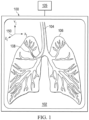
- an image-guided medical procedure which may be robotic-assisted or otherwise teleoperated, may be conducted in which a display system 100 may display a virtual navigation image 102, which includes an image reference frame (X I , Y I , Z I ) 150.
- An elongate device such as a medical instrument 104, may be registered (e.g., dynamically referenced) with an anatomic model 106 of a patient derived from preoperative image data obtained, for example, from a computerized tomography (CT) scan.
- CT computerized tomography
- the anatomic model 106 may include a target 108, such as a lesion or nodule of interest, which the procedure is intended to address (e.g., biopsy, treat, view).
- Generating the virtual navigation image 102 involves the registration of the image reference frame (X I , Y I , Z I ) 150 to a surgical reference frame (e.g., frame Xs, Ys, Zs of FIG. 11 ) of the anatomy and/or a medical instrument reference frame (e.g., frame X M , Y M , Z M of FIG. 11 ) of the medical instrument 104.
- This registration may rotate, translate, or otherwise manipulate, by rigid or non-rigid transforms, points associated with the segmented instrument shape from the image data and/or points associated with the shape data from a shape sensor disposed along a length of the medical instrument 104.
- This registration between the image and instrument reference frames may be achieved, for example, by using a point-based iterative closest point (ICP) technique as described in U.S. Pat. App. Pub. No. 2018/0240237, filed on February 12, 2018 , entitled “Systems and Methods of Registration for Image-Guided Surgery” and in U.S. Pat. App. Pub. No. 2018/0235709, filed on February 12, 2018 , entitled “Systems and Methods of Registration for Image-Guided Surgery,” which are incorporated by reference herein in their entireties.
- the registration may be achieved additionally or alternatively by another point cloud registration technique.
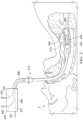
- FIG. 3 illustrates a medical system 300 that may include an outer catheter 320 through which a working catheter 330, and an imaging probe 340, an inflation lumen 321, and an evacuation lumen 322 may extend.
- the outer catheter 320 may represent the catheter 250 of FIG. 2 .
- a distal end 325 of the outer catheter 320 has been inserted into anatomical passageways 310, which may be the passageways 260, of the patient P.
- the inflation lumen 321 may be used to inflate one or more sealing devices, such as a balloon, to create a seal across one of the passageways 310.
- the imaging probe 340 may be positioned within an imaging probe sheath 342, which may additionally be inserted into the passageways 310 through the imaging lumen 324.
- the imaging probe 340 may be a radial probe, such as a radial endobronchial ultrasound (radial EBUS or REBUS) probe.
- the imaging probe 340 may include an imaging device 345 located near its distal end.
- the imaging device 345 may be a mechanical radial scanning device that is rotated about a longitudinal axis A of the imaging probe 340.
- the imaging device 345 may obtain images in an imaging field of view 347. In some examples, the field of view 347 represents a scanning direction of the imaging device 345.
- the catheter 510, the sheath 520, and the imaging probe 530 are independently extendable relative to one another.
- FIG. 6 illustrates a distal portion (e.g., distal of the portion shown in FIG. 5A ) of the imaging device 500 with the sheath 520 extended beyond a distal end 518 of the catheter 510 and illustrates the imaging probe 530 extended beyond a distal end 524 of the sheath 520.
- the telescoping extension shown in FIG. 6 may increase the available insertion distance of the imaging probe 530.
- the sheath 520 may be closed at its distal end 524, which prevents the imaging probe 530 from extending beyond the distal end 524. In some examples, such as the example shown in FIG.
- some or all of the sheath 520 may be rigid.
- a distal portion of the sheath 520 may be rigid, which may prevent the imaging probe 530 from bending when the imaging probe 530 is positioned within the distal end 524 of the sheath 520.
- a rigid distal portion of the sheath 520 may limit the amount of bending of the imaging probe 530 when the imaging probe 530 is extended a small distance beyond the distal end 524 of the sheath 520.
- the bending of the imaging probe 530 may be so limited that it is negligible.
- the rigidity of the sheath 520 may be actively controllable.
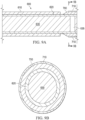
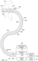
- the identification feature(s) may be more easily detected by the imaging device 635 when there is good acoustical coupling between the imaging probe 630 and the sheath 620.
- the clarity of the image captured by the imaging probe 630 e.g., captured by the imaging device 635
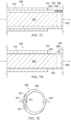
- a cavity 640 may be present between an outer surface of the imaging probe 630 and an inner surface of the sheath 620.
- the elongate wire 650 may be coupled to an outer surface 624 of the sheath 620.
- the elongate wire 650 may be coupled to the sheath 620 via one or more connection members (e.g., connection wires, scaffolding, and/or the like) such that the elongate wire 650 is spaced from the outer surface 624 of the sheath 620.
- a portion of the elongate wire 650 may be spaced from the outer surface 624 of the sheath 620, and wherein another portion of the elongate wire 650 may be in contact with the outer surface 624 of the sheath 620.
- the appearance of the elongate wire 650 may be more visible in the image captured by the imaging probe 630 when the elongate wire 650 is positioned outside of the sheath 620 than when the elongate wire 650 is positioned within the wall 622 of the sheath 620.
- a thicker elongate wire 650 may be more visible in the image captured by the imaging probe 630 than a thinner elongate wire 650.
- the elongate wire 650 may have a varying thickness along a length of the elongate wire 650.
- the insertion distance of the imaging probe 630 relative to the distal end of the catheter 610 may be measured.
- the control system may determine the insertion distance of the sheath 620 based on the thickness of the elongate wire 650 that is visible in the image captured by the imaging probe 630.
- the control system may determine the insertion distance of the imaging probe 630 based on the insertion distance of the sheath 620.
- control system may register the imaging data captured by the imaging probe 630 to the reference frame of the catheter 610 based on the insertion distance of the imaging probe 630 relative to the catheter 610. For example, the control system may determine the insertion distance of the imaging probe 630 relative to the sheath 620 based on the appearance of the identification feature (e.g., the elongate wire 650) that is visible in the image captured by the imaging probe 630. The control system may determine the insertion distance of the sheath 620 relative to the catheter 610 as discussed in greater detail below. Based on these relative insertion distance determinations, the control system may determine the insertion distance of the imaging probe 630 relative to the catheter 610. The control system may register the imaging data captured by the imaging probe 630 to the reference frame of the catheter 610 based on the insertion distance of the imaging probe 630 relative to the catheter 610.
- the identification feature e.g., the elongate wire 650
- control system may determine the rotational orientation of the imaging data captured by the imaging probe 630 relative to the rotational orientation of the sheath 650 based on the appearance of the elongate wire 650 in the imaging data captured by the imaging probe 630.
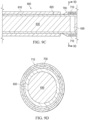
- Having a non-concentric portion in the sheath wall may allow for larger identification features to be placed in/on the sheath 620.
- the marker 660 may be larger (e.g., thicker) than the elongate wire 650 discussed above. Larger identification features may be more visible in the image captured by the imaging probe 630 than smaller identification features.
- the composite material may be, for example, a combination of a non-attenuating polymer (e.g., one or more PEBA polymers or one or more polyurethane polymers, such as Tecoflex 80A) and an attenuating material (e.g., tungsten particles, gas bubbles, hollow glass microspheres, and/or the like).
- the portion 625 may extend along an entire length of the sheath 620, along separate portions of the length of the sheath 620, or along a portion of the sheath 620, such as the distal portion.
- the portion 625 may be visible in the image captured by the imaging probe 630.
- the control system may identify the portion 625 in the image and determine a rotational orientation of the sheath 620 based on the identified portion 625.
- the identification feature may be an expandable member.
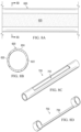
- an identification feature 700 may radially expand from a collapsed position to an expanded position.
- the identification feature 700 may be in the collapsed position when the sheath is within the catheter 610.
- the identification feature 700 is a balloon but may also be scaffolding, a spring-loaded feature, or any other expandable member.
- the balloon 700 itself may be detectable in the image captured by the imaging probe 630.
- a marker 710 may be coupled to the balloon 700. The marker 710 may be detectable in the image captured by the imaging probe 630.
- the marker 710 may be coupled to an outside surface of the balloon 700. Additionally or alternatively, the marker 710 may be positioned within the balloon 700 (e.g., embedded within the balloon 700) as shown in FIGS. 7C and 7D . In some examples, the marker 710 may surround the balloon 700 such that the marker 710 is concentric with the balloon 700. Alternatively, the marker 710 may surround a portion of the balloon 700 (e.g., a portion of the circumference of the balloon).
- multiple balloons may be coupled to the sheath 620 in some examples.
- the balloons may be aligned parallel with a longitudinal axis of the sheath 620.
- the balloons may form a spiral or other curved pattern around the sheath 620.
- each balloon may expand as each balloon is extended beyond the distal end 612 of the catheter 610.
- the balloons may be identifiable in intraoperative external image data, such as fluoroscopic image data, that may be captured as the sheath 620 is extended from the catheter 610.
- control system and/or a user may analyze the intraoperative external image data to determine how many balloons have expanded. Based on the number of expanded balloons (and any partially expanded balloons), the control system and/or the user may determine the insertion distance of the sheath 620. In examples when the sheath 620 and the imaging probe 630 are axially constrained, the insertion distance of the sheath 620 may also correspond to the insertion distance of the imaging probe 630. In examples when the balloons form a spiral or other curved pattern around the sheath 620, the balloons may be identifiable in the intraoperative external image data at different angles around the circumference of the sheath 620.
- the bending (e.g., pitch and/or yaw) of the imaging probe 630 relative to the longitudinal axis of the catheter 610 may be identified.
- the balloons may be identifiable in the image captured by the imaging probe 630.
- the control system and/or a user may analyze this image to determine how many balloons have expanded as the sheath 620 is extended from the catheter 610. Based on the number of expanded balloons (and any partially expanded balloons), the control system and/or the user may determine the bend angle (e.g., pitch and/or yaw) of the sheath 620.
- the balloons may be actively controllable.
- control system may send signals to one or more of the balloons to control which balloons are expanded and/or the amount of expansion, such as any partial expansion, of the balloons.
- control system may control the expansion of one or more balloons over time such that the balloons are open and closed in a temporal pattern. For example, a distalmost balloon may be expanded and when it reaches full expansion, the adjacent balloon may be expanded. In some examples, when the adjacent balloon reaches full expansion, the distalmost balloon may be deflated.
- the control system may control the expansion of the balloons according to any other temporal pattern.
- the user may test the articulation of the catheter 610 and may observe how the image captured by the imaging probe 630 changes during the articulation. Based on the observed changes in the captured image, the user may determine the registration between the captured image and the catheter 610. For example, if the user articulates the catheter 610 to a "3:00" (i.e., 3 o'clock) orientation and the captured image indicates that the catheter 610 is oriented in a "9:00" orientation, then the user may determine that the articulation of the catheter 610 and the captured image are inversely related.
- a "3:00" i.e., 3 o'clock
- GUI graphical user interface
- an image of a medical instrument may be displayed on the GUI, and the position of the image of the medical instrument may be updated as the medical instrument is navigated through the patient anatomy.
- one or more images of an imaging device may be displayed on the GUI.
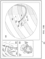
- the GUI 800 may also include a reduced anatomical model 820, an intraoperative external image 830 (e.g., a fluoroscopic image), a virtual path view 840, an intraoperative image 850, and an icon menu 870.
- the path view 840 may illustrate the view along a preoperatively planned traversal path 842 for the medical instrument 812 to follow through the anatomic passageways 816 identified in an anatomic model generated from preoperative image data (e.g., CT image data).
- control system and/or an image processing system may analyze the intraoperative external image 830 to determine how far into the sheath the imaging probe 860 is inserted to determine how far the distal end of the imaging probe 860 is extended from the distal end 814 of the medical instrument 812.
- a sensor at a proximal portion of the medical instrument 812 may measure how far the distal end of the imaging probe 860 is extended from the distal end 814 of the medical instrument 812.
- Other measurement techniques may be used without departing from the examples discussed herein.
- control system and/or the image processing system may analyze the intraoperative external image 830 to determine the off-axis bending (e.g., the pitch and/or the yaw) of the imaging probe 860.
- control system and/or the image processing system may analyze the intraoperative external image 830 to determine the orientation of the imaging device 862 at the distal end of the imaging probe 860.
- the imaging device 862 may be a radial EBUS transducer that rotates to obtain one or more ultrasound images.
- the orientation of the imaging device 862 may be seen in the intraoperative external image 830 when the imaging device 862 is not rotating.
- the appearance of the identification feature 890 in the intraoperative external image 830 is different for different off-axis bending orientations of the sheath 861.
- the control system may determine the off-axis bending of the imaging probe 860 based on the appearance of the identification feature 890 in the intraoperative external image 830.
- a proximal end of the imaging probe 860 may include a transmission mechanism that allows for finer adjustment of the insertion distance of the imaging probe 860.
- the transmission mechanism may allow for larger insertion movements at the proximal end of the imaging probe 860 to translate to smaller insertion movements at the distal end of the imaging probe 860.
- the proximal end of the imaging probe 860 is inserted 2cm, the distal end of the imaging probe 860 may be inserted 1mm. Any other insertion distance ratio may be achieved by the transmission mechanism.
- the imaging probe 860 may not bend or may experience negligible bending when the imaging probe 860 is extended from the medical instrument 812. In such examples, the control system may determine that there is no bending in the imaging probe 860. For example, the control system may determine that a longitudinal axis of the imaging probe 860 is substantially parallel with a longitudinal axis of the medical instrument 812 when the imaging probe 860 is extended from the medical instrument 812. In some alternative examples when the imaging probe 860 may be bent a negligible amount, the control system may determine the amount of bending in the imaging probe 860 using any one or more of the methods discussed above.
- the components discussed above may be part of a robotic-assisted system as described in further detail below.
- the robotic-assisted system may be suitable for use in, for example, surgical, robotic-assisted surgical, diagnostic, therapeutic, or biopsy procedures. While some examples are provided herein with respect to such procedures, any reference to medical or surgical instruments and medical or surgical methods is non-limiting.
- the systems, instruments, and methods described herein may be used for animals, human cadavers, animal cadavers, portions of human or animal anatomy, non-surgical diagnosis, as well as for industrial systems and general robotic, general robotic-assisted, or robotic medical systems.
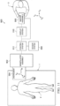
- Manipulator assembly 902 supports medical instrument 904 and may optionally include a plurality of actuators or motors that drive inputs on medical instrument 904 in response to commands from a control system 912.
- the actuators may optionally include drive systems that when coupled to medical instrument 904 may advance medical instrument 904 into a naturally or surgically created anatomic orifice.
- Medical system 900 also includes a display system 910 for displaying an image or representation of the surgical site and medical instrument 904 generated by sub-systems of sensor system 908.
- Display system 910 and master assembly 906 may be oriented so operator ⁇ can control medical instrument 904 and master assembly 906 with the perception of telepresence. Additional information regarding the medical system 900 and the medical instrument 904 may be found in International Application Publication No. WO 2018/195216, filed on April 18, 2018 , entitled "Graphical User Interface for Monitoring an Image-Guided Procedure," which is incorporated by reference herein in its entirety.
- the imaging system may be implemented as hardware, firmware, software or a combination thereof which interact with or are otherwise executed by one or more computer processors, which may include the processors of the control system 912.
- Tracking system 1030 may optionally track distal end 1018 and/or one or more of the segments 1024 using a shape sensor 1022.
- Shape sensor 1022 may optionally include an optical fiber aligned with flexible body 1016 (e.g., provided within an interior channel (not shown) or mounted externally). The optical fiber of shape sensor 1022 forms a fiber optic bend sensor for determining the shape of flexible body 1016.
- optical fibers including Fiber Bragg Gratings (FBGs) are used to provide strain measurements in structures in one or more dimensions.
- FBGs Fiber Bragg Gratings
- Flexible body 1016 may also house cables, linkages, or other steering controls (not shown) that extend between drive unit 1004 and distal end 1018 to controllably bend distal end 1018 as shown, for example, by broken dashed line depictions 1019 of distal end 1018.
- at least four cables are used to provide independent "up-down” steering to control a pitch of distal end 1018 and "left-right” steering to control a yaw of distal end 1018.
- Steerable elongate devices are described in detail in U.S. Patent Application No. 13/274,208, filed on October 14, 2011 , entitled “Catheter with Removable Vision Probe", which is incorporated by reference herein in its entirety.
- a computer is a machine that follows programmed instructions to perform mathematical or logical functions on input information to produce processed output information.
- a computer includes a logic unit that performs the mathematical or logical functions, and memory that stores the programmed instructions, the input information, and the output information.
- the term "computer” and similar terms, such as “processor” or “controller” or “control system”, are analogous.
Landscapes
- Health & Medical Sciences (AREA)
- Life Sciences & Earth Sciences (AREA)
- Engineering & Computer Science (AREA)
- Physics & Mathematics (AREA)
- Medical Informatics (AREA)
- Animal Behavior & Ethology (AREA)
- Radiology & Medical Imaging (AREA)
- Nuclear Medicine, Radiotherapy & Molecular Imaging (AREA)
- Biomedical Technology (AREA)
- Heart & Thoracic Surgery (AREA)
- Biophysics (AREA)
- Molecular Biology (AREA)
- Surgery (AREA)
- Pathology (AREA)
- General Health & Medical Sciences (AREA)
- Public Health (AREA)
- Veterinary Medicine (AREA)
- Computer Vision & Pattern Recognition (AREA)
- General Physics & Mathematics (AREA)
- Theoretical Computer Science (AREA)
- Endoscopes (AREA)
- Ultra Sonic Daignosis Equipment (AREA)
Applications Claiming Priority (3)
| Application Number | Priority Date | Filing Date | Title |
|---|---|---|---|
| US202163159188P | 2021-03-10 | 2021-03-10 | |
| PCT/US2022/019537 WO2022192392A1 (fr) | 2021-03-10 | 2022-03-09 | Systèmes et procédés d'enregistrement de données d'imagerie peropératoire |
| EP22712762.8A EP4304484B1 (fr) | 2021-03-10 | 2022-03-09 | Systèmes et procédés d'enregistrement de données d'imagerie peropératoire |
Related Parent Applications (1)
| Application Number | Title | Priority Date | Filing Date |
|---|---|---|---|
| EP22712762.8A Division EP4304484B1 (fr) | 2021-03-10 | 2022-03-09 | Systèmes et procédés d'enregistrement de données d'imagerie peropératoire |
Publications (2)
| Publication Number | Publication Date |
|---|---|
| EP4534035A2 true EP4534035A2 (fr) | 2025-04-09 |
| EP4534035A3 EP4534035A3 (fr) | 2025-06-11 |
Family
ID=80937177
Family Applications (2)
| Application Number | Title | Priority Date | Filing Date |
|---|---|---|---|
| EP25158896.8A Pending EP4534035A3 (fr) | 2021-03-10 | 2022-03-09 | Systèmes et procédés d'enregistrement de données d'image peropératoires |
| EP22712762.8A Active EP4304484B1 (fr) | 2021-03-10 | 2022-03-09 | Systèmes et procédés d'enregistrement de données d'imagerie peropératoire |
Family Applications After (1)
| Application Number | Title | Priority Date | Filing Date |
|---|---|---|---|
| EP22712762.8A Active EP4304484B1 (fr) | 2021-03-10 | 2022-03-09 | Systèmes et procédés d'enregistrement de données d'imagerie peropératoire |
Country Status (4)
| Country | Link |
|---|---|
| US (1) | US12573063B2 (fr) |
| EP (2) | EP4534035A3 (fr) |
| CN (1) | CN116940284A (fr) |
| WO (1) | WO2022192392A1 (fr) |
Families Citing this family (3)
| Publication number | Priority date | Publication date | Assignee | Title |
|---|---|---|---|---|
| US12408991B2 (en) | 2020-12-10 | 2025-09-09 | Magnisity Ltd. | Dynamic deformation tracking for navigational bronchoscopy |
| US20240074737A1 (en) * | 2022-09-07 | 2024-03-07 | Canon Medical Systems Corporation | Medical image processing apparatus, x-ray diagnostic system, and non-transitory computer-readable storage medium storing medical image processing program |
| US20250143545A1 (en) * | 2023-06-07 | 2025-05-08 | Auris Health, Inc. | Endoscope protrusion calibration |
Citations (7)
| Publication number | Priority date | Publication date | Assignee | Title |
|---|---|---|---|---|
| US4705604A (en) | 1984-07-06 | 1987-11-10 | Solvay & Cie. (Societe Anonyme) | Process for extracting poly-beta-hydroxybutyrates by means of a solvent from an aqueous suspension of microorganisms |
| US6380732B1 (en) | 1997-02-13 | 2002-04-30 | Super Dimension Ltd. | Six-degree of freedom tracking system having a passive transponder on the object being tracked |
| US6389187B1 (en) | 1997-06-20 | 2002-05-14 | Qinetiq Limited | Optical fiber bend sensor |
| WO2016025465A1 (fr) | 2014-08-14 | 2016-02-18 | Intuitive Surgical Operations, Inc. | Systèmes et procédés de nettoyage d'un instrument endoscopique |
| US20180240237A1 (en) | 2015-08-14 | 2018-08-23 | Intuitive Surgical Operations, Inc. | Systems and Methods of Registration for Image-Guided Surgery |
| US20180235709A1 (en) | 2015-08-14 | 2018-08-23 | Intuitive Surgical Operations, Inc. | Systems and Methods of Registration for Image-Guided Surgery |
| WO2018195216A1 (fr) | 2017-04-18 | 2018-10-25 | Intuitive Surgical Operations, Inc. | Interface utilisateur graphique pour surveiller une procédure guidée par image |
Family Cites Families (85)
| Publication number | Priority date | Publication date | Assignee | Title |
|---|---|---|---|---|
| US5243988A (en) * | 1991-03-13 | 1993-09-14 | Scimed Life Systems, Inc. | Intravascular imaging apparatus and methods for use and manufacture |
| US20020115941A1 (en) | 1993-04-15 | 2002-08-22 | Scimed Life Systems, Inc. | Systems and methods using annotated images for controlling the use of diagnostic or therapeutic instruments in interior body regions |
| US6468265B1 (en) | 1998-11-20 | 2002-10-22 | Intuitive Surgical, Inc. | Performing cardiac surgery without cardioplegia |
| US10820949B2 (en) | 1999-04-07 | 2020-11-03 | Intuitive Surgical Operations, Inc. | Medical robotic system with dynamically adjustable slave manipulator characteristics |
| US6709667B1 (en) | 1999-08-23 | 2004-03-23 | Conceptus, Inc. | Deployment actuation system for intrafallopian contraception |
| US8239001B2 (en) | 2003-10-17 | 2012-08-07 | Medtronic Navigation, Inc. | Method and apparatus for surgical navigation |
| US7206462B1 (en) | 2000-03-17 | 2007-04-17 | The General Hospital Corporation | Method and system for the detection, comparison and volumetric quantification of pulmonary nodules on medical computed tomography scans |
| US6468203B2 (en) | 2000-04-03 | 2002-10-22 | Neoguide Systems, Inc. | Steerable endoscope and improved method of insertion |
| US8517923B2 (en) | 2000-04-03 | 2013-08-27 | Intuitive Surgical Operations, Inc. | Apparatus and methods for facilitating treatment of tissue via improved delivery of energy based and non-energy based modalities |
| US7179220B2 (en) | 2001-02-07 | 2007-02-20 | Siemens Corporate Research, Inc. | Method for guiding flexible instrument procedures |
| US7607440B2 (en) | 2001-06-07 | 2009-10-27 | Intuitive Surgical, Inc. | Methods and apparatus for surgical planning |
| GB2383245B (en) | 2001-11-05 | 2005-05-18 | Canon Europa Nv | Image processing apparatus |
| US20030093067A1 (en) | 2001-11-09 | 2003-05-15 | Scimed Life Systems, Inc. | Systems and methods for guiding catheters using registered images |
| JP2005514145A (ja) | 2002-01-09 | 2005-05-19 | ネオガイド システムズ, インコーポレイテッド | 内視鏡結腸切除のための装置および方法 |
| US7599730B2 (en) | 2002-11-19 | 2009-10-06 | Medtronic Navigation, Inc. | Navigation system for cardiac therapies |
| US7090639B2 (en) | 2003-05-29 | 2006-08-15 | Biosense, Inc. | Ultrasound catheter calibration system |
| EP1691666B1 (fr) | 2003-12-12 | 2012-05-30 | University of Washington | Systeme de guidage et d'interface en 3d pour catheterscope |
| CN100515332C (zh) | 2004-02-18 | 2009-07-22 | 皇家飞利浦电子股份有限公司 | 用于确定导管在脉管系统中位置的设备和方法 |
| US10227063B2 (en) | 2004-02-26 | 2019-03-12 | Geelux Holdings, Ltd. | Method and apparatus for biological evaluation |
| US8209027B2 (en) | 2004-07-07 | 2012-06-26 | The Cleveland Clinic Foundation | System and method to design structure for delivering electrical energy to tissue |
| US7781724B2 (en) | 2004-07-16 | 2010-08-24 | Luna Innovations Incorporated | Fiber optic position and shape sensing device and method relating thereto |
| US7772541B2 (en) | 2004-07-16 | 2010-08-10 | Luna Innnovations Incorporated | Fiber optic position and/or shape sensing based on rayleigh scatter |
| US20060013523A1 (en) | 2004-07-16 | 2006-01-19 | Luna Innovations Incorporated | Fiber optic position and shape sensing device and method relating thereto |
| US8611983B2 (en) | 2005-01-18 | 2013-12-17 | Philips Electronics Ltd | Method and apparatus for guiding an instrument to a target in the lung |
| US20080015569A1 (en) * | 2005-02-02 | 2008-01-17 | Voyage Medical, Inc. | Methods and apparatus for treatment of atrial fibrillation |
| JP2008537691A (ja) | 2005-03-16 | 2008-09-25 | コーネル リサーチ ファンデーション,インコーポレーテッド | 診断用精密検査におけるイメージング・ソフトウエアの領域を拡張する方法 |
| US10555775B2 (en) | 2005-05-16 | 2020-02-11 | Intuitive Surgical Operations, Inc. | Methods and system for performing 3-D tool tracking by fusion of sensor and/or camera derived data during minimally invasive robotic surgery |
| US9526587B2 (en) | 2008-12-31 | 2016-12-27 | Intuitive Surgical Operations, Inc. | Fiducial marker design and detection for locating surgical instrument in images |
| US8398541B2 (en) | 2006-06-06 | 2013-03-19 | Intuitive Surgical Operations, Inc. | Interactive user interfaces for robotic minimally invasive surgical systems |
| DE102005030647B3 (de) * | 2005-06-30 | 2007-03-22 | Siemens Ag | Vorrichtung und Verfahren zur intraluminalen Bildgebung für die Rekonstruktion von 3D-Bilddatensätzen |
| AU2006302057B2 (en) | 2005-10-11 | 2013-03-21 | Carnegie Mellon University | Sensor guided catheter navigation system |
| US20070106147A1 (en) | 2005-11-01 | 2007-05-10 | Altmann Andres C | Controlling direction of ultrasound imaging catheter |
| US8303505B2 (en) | 2005-12-02 | 2012-11-06 | Abbott Cardiovascular Systems Inc. | Methods and apparatuses for image guided medical procedures |
| US7930065B2 (en) | 2005-12-30 | 2011-04-19 | Intuitive Surgical Operations, Inc. | Robotic surgery system including position sensors using fiber bragg gratings |
| US7804990B2 (en) | 2006-01-25 | 2010-09-28 | Siemens Medical Solutions Usa, Inc. | System and method for labeling and identifying lymph nodes in medical images |
| US9186046B2 (en) | 2007-08-14 | 2015-11-17 | Koninklijke Philips Electronics N.V. | Robotic instrument systems and methods utilizing optical fiber sensor |
| US9408530B2 (en) | 2006-04-12 | 2016-08-09 | Gearbox, Llc | Parameter-based navigation by a lumen traveling device |
| US8112292B2 (en) | 2006-04-21 | 2012-02-07 | Medtronic Navigation, Inc. | Method and apparatus for optimizing a therapy |
| US20080064927A1 (en) | 2006-06-13 | 2008-03-13 | Intuitive Surgical, Inc. | Minimally invasrive surgery guide tube |
| WO2008005953A2 (fr) | 2006-06-30 | 2008-01-10 | Broncus Technologies, Inc. | Sélection de site de dérivation des voies aériennes et planification d'un traitement |
| US20080082109A1 (en) | 2006-09-08 | 2008-04-03 | Hansen Medical, Inc. | Robotic surgical system with forward-oriented field of view guide instrument navigation |
| US8160676B2 (en) | 2006-09-08 | 2012-04-17 | Medtronic, Inc. | Method for planning a surgical procedure |
| US8248414B2 (en) | 2006-09-18 | 2012-08-21 | Stryker Corporation | Multi-dimensional navigation of endoscopic video |
| US7735349B2 (en) * | 2007-01-31 | 2010-06-15 | Biosense Websters, Inc. | Correlation of ultrasound images and gated position measurements |
| US20090156895A1 (en) | 2007-01-31 | 2009-06-18 | The Penn State Research Foundation | Precise endoscopic planning and visualization |
| EP2139422B1 (fr) | 2007-03-26 | 2016-10-26 | Hansen Medical, Inc. | Systèmes et procédés de cathéters robotiques |
| US8428690B2 (en) | 2007-05-16 | 2013-04-23 | General Electric Company | Intracardiac echocardiography image reconstruction in combination with position tracking system |
| US8175677B2 (en) | 2007-06-07 | 2012-05-08 | MRI Interventions, Inc. | MRI-guided medical interventional systems and methods |
| US8315689B2 (en) | 2007-09-24 | 2012-11-20 | MRI Interventions, Inc. | MRI surgical systems for real-time visualizations using MRI image data and predefined data of surgical tools |
| CN101375805A (zh) | 2007-12-29 | 2009-03-04 | 清华大学深圳研究生院 | 一种计算机辅助引导电子内窥镜操作的方法和系统 |
| US8219179B2 (en) | 2008-03-06 | 2012-07-10 | Vida Diagnostics, Inc. | Systems and methods for navigation within a branched structure of a body |
| WO2009120953A2 (fr) | 2008-03-27 | 2009-10-01 | Mayo Foundation For Medical Education And Research | Systèmes et procédés de navigation et de prélèvement de tissu |
| US8340751B2 (en) | 2008-04-18 | 2012-12-25 | Medtronic, Inc. | Method and apparatus for determining tracking a virtual point defined relative to a tracked member |
| US8228368B2 (en) | 2008-04-26 | 2012-07-24 | Intuitive Surgical Operations, Inc. | Augmented stereoscopic visualization for a surgical robot using a captured fluorescence image and captured stereoscopic visible images |
| EP2303157A1 (fr) | 2008-06-25 | 2011-04-06 | Koninklijke Philips Electronics N.V. | Canule nichée pour chirurgie minimalement invasive |
| RU2011120186A (ru) | 2008-10-20 | 2012-11-27 | Конинклейке Филипс Электроникс, Н.В. | Способ и система локализации на основе изображений |
| CN102196782B (zh) | 2008-10-31 | 2014-04-30 | 皇家飞利浦电子股份有限公司 | 在医学过程中进行电磁跟踪的方法和系统 |
| US20100125284A1 (en) | 2008-11-20 | 2010-05-20 | Hansen Medical, Inc. | Registered instrument movement integration |
| US10004387B2 (en) | 2009-03-26 | 2018-06-26 | Intuitive Surgical Operations, Inc. | Method and system for assisting an operator in endoscopic navigation |
| US8611984B2 (en) | 2009-04-08 | 2013-12-17 | Covidien Lp | Locatable catheter |
| RU2558521C2 (ru) | 2009-06-05 | 2015-08-10 | Кониклейке Филипс Электроникс, Н.В. | Система и способ интегрированной биопсии и лечения |
| US9144431B2 (en) | 2009-09-30 | 2015-09-29 | Aegis Medical Innovations Inc. | Enhanced signal navigation and capture systems and methods |
| US20120059378A1 (en) | 2009-11-25 | 2012-03-08 | James David Farrell | Efficient Sculpting System |
| WO2011081922A1 (fr) | 2009-12-14 | 2011-07-07 | Smith & Nephew, Inc. | Système de localisation du lca guidé par visualisation |
| JP4728456B1 (ja) | 2010-02-22 | 2011-07-20 | オリンパスメディカルシステムズ株式会社 | 医療機器 |
| US8774903B2 (en) | 2010-03-26 | 2014-07-08 | Headwater Partners Ii Llc | Medical imaging apparatus and method |
| US8787635B2 (en) | 2010-05-03 | 2014-07-22 | Siemens Aktiengesellschaft | Optimization of multiple candidates in medical device or feature tracking |
| US9858475B2 (en) | 2010-05-14 | 2018-01-02 | Intuitive Surgical Operations, Inc. | Method and system of hand segmentation and overlay using depth data |
| CN101862205A (zh) | 2010-05-25 | 2010-10-20 | 中国人民解放军第四军医大学 | 一种结合术前影像的术中组织跟踪方法 |
| AU2011272764B2 (en) * | 2010-06-30 | 2015-11-19 | Muffin Incorporated | Percutaneous, ultrasound-guided introduction of medical devices |
| WO2012106310A1 (fr) | 2011-02-04 | 2012-08-09 | The Penn State Research Foundation | Procédé et dispositif pour déterminer l'emplacement d'un endoscope |
| US8827934B2 (en) | 2011-05-13 | 2014-09-09 | Intuitive Surgical Operations, Inc. | Method and system for determining information of extrema during expansion and contraction cycles of an object |
| US8900131B2 (en) | 2011-05-13 | 2014-12-02 | Intuitive Surgical Operations, Inc. | Medical system providing dynamic registration of a model of an anatomical structure for image-guided surgery |
| DE102011076188B4 (de) | 2011-05-20 | 2013-03-21 | Siemens Aktiengesellschaft | Vorrichtung und Verfahren zur Planung einer endovaskulären Prozedur mit einem medizinischen Instrument |
| US10734116B2 (en) | 2011-10-04 | 2020-08-04 | Quantant Technology, Inc. | Remote cloud based medical image sharing and rendering semi-automated or fully automated network and/or web-based, 3D and/or 4D imaging of anatomy for training, rehearsing and/or conducting medical procedures, using multiple standard X-ray and/or other imaging projections, without a need for special hardware and/or systems and/or pre-processing/analysis of a captured image data |
| US9105200B2 (en) | 2011-10-04 | 2015-08-11 | Quantant Technology, Inc. | Semi-automated or fully automated, network and/or web-based, 3D and/or 4D imaging of anatomy for training, rehearsing and/or conducting medical procedures, using multiple standard X-ray and/or other imaging projections, without a need for special hardware and/or systems and/or pre-processing/analysis of a captured image data |
| US9452276B2 (en) | 2011-10-14 | 2016-09-27 | Intuitive Surgical Operations, Inc. | Catheter with removable vision probe |
| WO2013149034A2 (fr) | 2012-03-28 | 2013-10-03 | Cibiem, Inc. | Planification et évaluation de la modulation d'un glomus carotidien |
| US9552660B2 (en) | 2012-08-30 | 2017-01-24 | Truevision Systems, Inc. | Imaging system and methods displaying a fused multidimensional reconstructed image |
| US20140188440A1 (en) | 2012-12-31 | 2014-07-03 | Intuitive Surgical Operations, Inc. | Systems And Methods For Interventional Procedure Planning |
| US9833221B2 (en) | 2013-03-15 | 2017-12-05 | Lightlab Imaging, Inc. | Apparatus and method of image registration |
| US10542868B2 (en) | 2014-09-10 | 2020-01-28 | Intuitive Surgical Operations, Inc. | Devices, systems, and methods using mating catheter tips and tools |
| US20190142528A1 (en) * | 2016-05-23 | 2019-05-16 | Lx Medical Corporation | Method and system for image-guided procedures |
| US11266387B2 (en) | 2016-06-15 | 2022-03-08 | Intuitive Surgical Operations, Inc. | Systems and methods of integrated real-time visualization |
| CN112004496B (zh) | 2018-04-25 | 2024-10-18 | 直观外科手术操作公司 | 与细长装置有关的系统和方法 |
-
2022
- 2022-03-09 CN CN202280017451.9A patent/CN116940284A/zh active Pending
- 2022-03-09 US US18/549,819 patent/US12573063B2/en active Active
- 2022-03-09 EP EP25158896.8A patent/EP4534035A3/fr active Pending
- 2022-03-09 WO PCT/US2022/019537 patent/WO2022192392A1/fr not_active Ceased
- 2022-03-09 EP EP22712762.8A patent/EP4304484B1/fr active Active
Patent Citations (7)
| Publication number | Priority date | Publication date | Assignee | Title |
|---|---|---|---|---|
| US4705604A (en) | 1984-07-06 | 1987-11-10 | Solvay & Cie. (Societe Anonyme) | Process for extracting poly-beta-hydroxybutyrates by means of a solvent from an aqueous suspension of microorganisms |
| US6380732B1 (en) | 1997-02-13 | 2002-04-30 | Super Dimension Ltd. | Six-degree of freedom tracking system having a passive transponder on the object being tracked |
| US6389187B1 (en) | 1997-06-20 | 2002-05-14 | Qinetiq Limited | Optical fiber bend sensor |
| WO2016025465A1 (fr) | 2014-08-14 | 2016-02-18 | Intuitive Surgical Operations, Inc. | Systèmes et procédés de nettoyage d'un instrument endoscopique |
| US20180240237A1 (en) | 2015-08-14 | 2018-08-23 | Intuitive Surgical Operations, Inc. | Systems and Methods of Registration for Image-Guided Surgery |
| US20180235709A1 (en) | 2015-08-14 | 2018-08-23 | Intuitive Surgical Operations, Inc. | Systems and Methods of Registration for Image-Guided Surgery |
| WO2018195216A1 (fr) | 2017-04-18 | 2018-10-25 | Intuitive Surgical Operations, Inc. | Interface utilisateur graphique pour surveiller une procédure guidée par image |
Also Published As
| Publication number | Publication date |
|---|---|
| EP4304484B1 (fr) | 2025-02-26 |
| EP4534035A3 (fr) | 2025-06-11 |
| US20240153113A1 (en) | 2024-05-09 |
| WO2022192392A1 (fr) | 2022-09-15 |
| EP4304484A1 (fr) | 2024-01-17 |
| US12573063B2 (en) | 2026-03-10 |
| CN116940284A (zh) | 2023-10-24 |
Similar Documents
| Publication | Publication Date | Title |
|---|---|---|
| US12564313B2 (en) | Systems and methods of integrated real-time visualization | |
| US12502224B2 (en) | Systems and methods for registering elongate devices to three-dimensional images in image-guided procedures | |
| CN116585031B (zh) | 用于智能种子配准的系统和方法 | |
| CN109069136B (zh) | 用于经皮手术的过程 | |
| EP4304484B1 (fr) | Systèmes et procédés d'enregistrement de données d'imagerie peropératoire | |
| CN119856989A (zh) | 用于在图像引导手术中使用配准荧光透视图像的系统和方法 | |
| CN116829089A (zh) | 用于基于术中成像更新图形用户界面的系统 | |
| US20240099777A1 (en) | Systems and methods for updating a target location using intraoperative image data | |
| CN112074867A (zh) | 与用于图像引导手术的配准有关的系统和方法 | |
| US20260069363A1 (en) | Systems and methods for updating a target location using intraoperative image data | |
| EP4710861A2 (fr) | Systèmes et procédés d'instrument allongé à ultrasons | |
| EP4663093A2 (fr) | Systèmes d'alignement de l'anatomie d'un patient | |
| US20240349984A1 (en) | Systems and methods for generating images of a selected imaging plane using a forward-facing imaging array | |
| CN121079052A (zh) | 用于基于术中成像数据在术中更新图形用户界面的系统和方法 | |
| WO2024006852A1 (fr) | Systèmes et procédés de détermination d'un emplacement de déploiement d'un instrument médical | |
| WO2024058994A1 (fr) | Système d'imagerie avec aiguille alignée sur le champ de vision |
Legal Events
| Date | Code | Title | Description |
|---|---|---|---|
| PUAI | Public reference made under article 153(3) epc to a published international application that has entered the european phase |
Free format text: ORIGINAL CODE: 0009012 |
|
| STAA | Information on the status of an ep patent application or granted ep patent |
Free format text: STATUS: THE APPLICATION HAS BEEN PUBLISHED |
|
| AC | Divisional application: reference to earlier application |
Ref document number: 4304484 Country of ref document: EP Kind code of ref document: P |
|
| AK | Designated contracting states |
Kind code of ref document: A2 Designated state(s): AL AT BE BG CH CY CZ DE DK EE ES FI FR GB GR HR HU IE IS IT LI LT LU LV MC MK MT NL NO PL PT RO RS SE SI SK SM TR |
|
| REG | Reference to a national code |
Ref country code: DE Ref legal event code: R079 Free format text: PREVIOUS MAIN CLASS: A61B0090000000 Ipc: A61B0008120000 |
|
| PUAL | Search report despatched |
Free format text: ORIGINAL CODE: 0009013 |
|
| AK | Designated contracting states |
Kind code of ref document: A3 Designated state(s): AL AT BE BG CH CY CZ DE DK EE ES FI FR GB GR HR HU IE IS IT LI LT LU LV MC MK MT NL NO PL PT RO RS SE SI SK SM TR |
|
| RIC1 | Information provided on ipc code assigned before grant |
Ipc: A61B 90/00 20160101ALN20250502BHEP Ipc: A61B 8/08 20060101ALN20250502BHEP Ipc: A61B 8/00 20060101ALI20250502BHEP Ipc: A61B 8/12 20060101AFI20250502BHEP |
|
| STAA | Information on the status of an ep patent application or granted ep patent |
Free format text: STATUS: REQUEST FOR EXAMINATION WAS MADE |
|
| 17P | Request for examination filed |
Effective date: 20251211 |
|
| GRAP | Despatch of communication of intention to grant a patent |
Free format text: ORIGINAL CODE: EPIDOSNIGR1 |
|
| STAA | Information on the status of an ep patent application or granted ep patent |
Free format text: STATUS: GRANT OF PATENT IS INTENDED |
|
| RIC1 | Information provided on ipc code assigned before grant |
Ipc: A61B 8/12 20060101AFI20260224BHEP Ipc: A61B 8/00 20060101ALI20260224BHEP Ipc: A61B 8/08 20060101ALN20260224BHEP Ipc: A61B 90/00 20160101ALN20260224BHEP |
|
| INTG | Intention to grant announced |
Effective date: 20260305 |