EP4534041A1 - Dental implant and dental implant assembly having the same - Google Patents
Dental implant and dental implant assembly having the same Download PDFInfo
- Publication number
- EP4534041A1 EP4534041A1 EP24204726.4A EP24204726A EP4534041A1 EP 4534041 A1 EP4534041 A1 EP 4534041A1 EP 24204726 A EP24204726 A EP 24204726A EP 4534041 A1 EP4534041 A1 EP 4534041A1
- Authority
- EP
- European Patent Office
- Prior art keywords
- dental implant
- polygonal
- upper side
- abutment
- side inclined
- Prior art date
- Legal status (The legal status is an assumption and is not a legal conclusion. Google has not performed a legal analysis and makes no representation as to the accuracy of the status listed.)
- Pending
Links
Images





Classifications
-
- A—HUMAN NECESSITIES
- A61—MEDICAL OR VETERINARY SCIENCE; HYGIENE
- A61C—DENTISTRY; APPARATUS OR METHODS FOR ORAL OR DENTAL HYGIENE
- A61C8/00—Means to be fixed to the jaw-bone for consolidating natural teeth or for fixing dental prostheses thereon; Dental implants; Implanting tools
- A61C8/0018—Means to be fixed to the jaw-bone for consolidating natural teeth or for fixing dental prostheses thereon; Dental implants; Implanting tools characterised by the shape
- A61C8/0022—Self-screwing
-
- A—HUMAN NECESSITIES
- A61—MEDICAL OR VETERINARY SCIENCE; HYGIENE
- A61C—DENTISTRY; APPARATUS OR METHODS FOR ORAL OR DENTAL HYGIENE
- A61C8/00—Means to be fixed to the jaw-bone for consolidating natural teeth or for fixing dental prostheses thereon; Dental implants; Implanting tools
- A61C8/0048—Connecting the upper structure to the implant, e.g. bridging bars
- A61C8/005—Connecting devices for joining an upper structure with an implant member, e.g. spacers
-
- A—HUMAN NECESSITIES
- A61—MEDICAL OR VETERINARY SCIENCE; HYGIENE
- A61C—DENTISTRY; APPARATUS OR METHODS FOR ORAL OR DENTAL HYGIENE
- A61C8/00—Means to be fixed to the jaw-bone for consolidating natural teeth or for fixing dental prostheses thereon; Dental implants; Implanting tools
- A61C8/0048—Connecting the upper structure to the implant, e.g. bridging bars
- A61C8/005—Connecting devices for joining an upper structure with an implant member, e.g. spacers
- A61C8/0063—Connecting devices for joining an upper structure with an implant member, e.g. spacers with an internal sleeve
-
- A—HUMAN NECESSITIES
- A61—MEDICAL OR VETERINARY SCIENCE; HYGIENE
- A61C—DENTISTRY; APPARATUS OR METHODS FOR ORAL OR DENTAL HYGIENE
- A61C8/00—Means to be fixed to the jaw-bone for consolidating natural teeth or for fixing dental prostheses thereon; Dental implants; Implanting tools
- A61C8/0048—Connecting the upper structure to the implant, e.g. bridging bars
- A61C8/005—Connecting devices for joining an upper structure with an implant member, e.g. spacers
- A61C8/0068—Connecting devices for joining an upper structure with an implant member, e.g. spacers with an additional screw
-
- A—HUMAN NECESSITIES
- A61—MEDICAL OR VETERINARY SCIENCE; HYGIENE
- A61C—DENTISTRY; APPARATUS OR METHODS FOR ORAL OR DENTAL HYGIENE
- A61C8/00—Means to be fixed to the jaw-bone for consolidating natural teeth or for fixing dental prostheses thereon; Dental implants; Implanting tools
- A61C8/0048—Connecting the upper structure to the implant, e.g. bridging bars
- A61C8/005—Connecting devices for joining an upper structure with an implant member, e.g. spacers
- A61C8/0069—Connecting devices for joining an upper structure with an implant member, e.g. spacers tapered or conical connection
-
- A—HUMAN NECESSITIES
- A61—MEDICAL OR VETERINARY SCIENCE; HYGIENE
- A61C—DENTISTRY; APPARATUS OR METHODS FOR ORAL OR DENTAL HYGIENE
- A61C8/00—Means to be fixed to the jaw-bone for consolidating natural teeth or for fixing dental prostheses thereon; Dental implants; Implanting tools
- A61C8/0048—Connecting the upper structure to the implant, e.g. bridging bars
- A61C8/005—Connecting devices for joining an upper structure with an implant member, e.g. spacers
- A61C8/0074—Connecting devices for joining an upper structure with an implant member, e.g. spacers with external threads
Definitions
- the present invention relates to a dental implant and a dental implant assembly having the same.
- implants (hereinafter referred to simply as "implants") inserted into the alveolar bone have been used for a long time, and one of titanium, a titanium alloy material, and a ceramic material that have excellent biocompatibility is selected and used as a material of implants that are commonly used nowadays.
- Implants must be manufactured to not only be able to functionally substitute for the actual teeth but also be able to be used for as long as the actual teeth by properly distributing the load applied to the teeth.
- Implants implanted into the alveolar bone are broadly classified into an external connection type and an internal connection type according to the form in which an implant is coupled to an abutment.
- the external connection type has an advantage in that the implant inserted into the bone is relatively sturdy, but has a disadvantage in that bone resorption may occur at a boundary part due to a wide gap between the implant and the abutment at an initial stage after the implant is implanted, which makes it prone to bacterial colonization.
- the internal connection type has been mainly used.
- a coupling structure to which a lower end of an abutment is coupled and which includes a hexagonal part or the like is formed inside an implant, and an upper end part of the coupling structure on which the abutment is seated is formed to be inclined.
- the internal connection type has an advantage in that the implant implantation success rate is high due to minimizing the initial bone resorption by eliminating a space in which bacterial colonization may occur.
- the internal connection type has a disadvantage in that the possibility of fracture of the implant inserted into the bone is relatively high due to a structural limitation caused by the abutment entering the implant.
- Fracture is caused by fatigue, which is a phenomenon in which the strength of a material or structure decreases and ultimately destruction occurs as the number of repetitions of stress increases when repeated stress occurs in the material or structure.
- a dental implant is a structure for replacing a lost tooth and repeatedly receives stress due to masticatory movements, and thus the possibility of an occurrence of fatigue destruction (generally referred to as "fatigue fracture”) cannot be eliminated.
- a vertical masticatory force in an axial direction of an implant and a horizontal masticatory force perpendicular to the axial direction may act in combination on an abutment. Since a lower end of the abutment that is coupled to the inside of the implant periodically applies tensile stress to the internal structure of the implant, fatigue fracture in the form of vertical fracture or horizontal fracture may be caused in the implant.
- the present invention is directed to providing a dental implant and a dental implant assembly having the same that can secure high stiffness by including an internal groove having an internal structure and dimensions that facilitate stress distribution.
- the present invention provides a dental implant forming an artificial dental root by being implanted into an alveolar bone according to rotation about an axis, the dental implant including an internal groove formed inside a top portion to enable coupling of an abutment for prosthesis supporting, and an external screw part having threads formed from a top of an outer peripheral surface to a bottom thereof to enable implantation into the alveolar bone, wherein the internal groove includes an upper side inclined part positioned at a top entrance part of the dental implant and having a circular cross-section and an inner diameter gradually decreasing downward, a polygonal part formed below the upper side inclined part and having a transverse cross-section formed in a polygonal shape, a boring part formed below the polygonal part and having a circular shape whose diameter is larger than a diameter of a circle circumscribing the polygonal shape of the polygonal part, a circular vertical part formed below the boring part, and an internal screw part formed below the circular vertical part and having threads for abutment coupling, whose diameter is smaller than
- a ratio of a thickness of a wall of the circular vertical part, which is perpendicular to the axis, to a maximum outer diameter of the dental implant may be set to range from 0.15 to 0.3.
- an inner diameter of the circular vertical part may be set to be 0.5 mm to 1.8 mm less than a maximum inner diameter of the upper side inclined part.
- a ratio of a depth from a topmost of the upper side inclined part to a bottommost of the circular vertical part to a depth from the topmost of the upper side inclined part to a bottommost of the internal screw part may be set to range from 0.5 to 0.7.
- the depth from the topmost of the upper side inclined part to the bottommost of the internal screw part may be set to range from 4 mm to 7 mm.
- the depth from the topmost of the upper side inclined part to the bottommost of the circular vertical part may be set to range from 3 mm to 5 mm.
- the external screw part may include an external top thread section machined down to a predetermined section downward from a top of an outer peripheral surface of the dental implant so that first crests having a first height and first valleys having a first depth are formed by a first bit, and an external bottom thread section machined below the external top thread section so that second crests having a second height and second valleys having a second depth are formed by a second bit having a machining surface shape and a width that are different from a machining surface shape and a width of the first bit, wherein the first height of the first crests may be formed to be smaller than the second height of the second crests, and the first depth of the first valleys may be formed to be smaller than the second depth of the second valleys.
- the threads of the external top thread section and the external bottom thread section may have the same pitches and the same crest widths.
- the first valleys and the second valleys may include a first curved part connecting from an upper portion of the valley to a side portion thereof and a second curved part connecting from the side portion of the valley to a lower portion thereof.
- a curvature of the first curved part may be larger than a curvature of the second curved part.
- the first valleys and the second valleys may be formed to be horizontally asymmetrical about a virtual line that is perpendicular to the axis and passes through a center of a width of the valleys.
- a cutting edge formed to be partially cut may be provided at a bottom of the outer peripheral surface of the dental implant, and the cutting edge may include a reverse helical section formed in an opposite direction of a helical direction of the threads and a helical section formed in the helical direction of the threads.
- the present invention provides a dental implant assembly including a dental implant forming an artificial dental root by being implanted into an alveolar bone according to rotation about an axis and an abutment coupled to the dental implant to support a prosthesis and having a fastening screw insertion hole formed therein, which extends from a top of the abutment to a bottom thereof to enable insertion of a fastening screw, wherein the dental implant includes an internal groove formed inside a top portion to enable coupling of an abutment for prosthesis supporting, and an external screw part having threads formed from a top of an outer peripheral surface to a bottom thereof to enable implantation into the alveolar bone, wherein the internal groove includes an upper side inclined part positioned at a top entrance part of the dental implant and having a circular cross-section and an inner diameter gradually decreasing downward, a polygonal part formed below the upper side inclined part and having a transverse cross-section formed in a polygonal shape, a boring part formed below the polygonal part and having a circular shape whose
- the abutment may include an upper side part configured to protrude to an outer portion of the dental implant and have the prosthesis attached thereto and a lower side part disposed below the upper side part and inserted into the internal groove, wherein the abutment may further include a holding part disposed at a bottom of the lower side part and configured to be elastically deformed and forcibly fitted into an inner circumferential surface of the circular vertical part to temporarily fix the abutment to an inner portion of the dental implant when the abutment is inserted into the dental implant.
- the holding part may be provided as a plurality of holding parts that are disposed to be spaced apart along a periphery of the bottom of the lower side part or may be provided as a single holding part that is formed to form a closed loop along the periphery of the bottom of the lower side part.
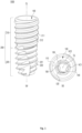
- FIGS. 1A and 1B are a perspective view and a plan view, respectively, of a dental implant according to the present invention
- FIG 2 is a front view of the dental implant according to the present invention
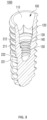
- FIG 3 is a cross-sectional perspective view of the dental implant according to the present invention
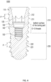
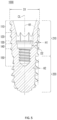
- FIGS. 4 and 5 are cross-sectional views of the dental implant according to the present invention
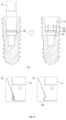
- FIG 6A is a view for describing a method of machining a polygonal part according to the present invention
- FIGS. 1A and 1B are a perspective view and a plan view, respectively, of a dental implant according to the present invention
- FIG 2 is a front view of the dental implant according to the present invention
- FIG 3 is a cross-sectional perspective view of the dental implant according to the present invention
- FIGS. 4 and 5 are cross-sectional views of the dental implant according to the present invention
- FIG 6A is a view for describing a method of machining a polygonal part according to the present invention
- FIG 6B and 6C are views for comparing a case in which a boring part is absent and the boring part is present when machining the polygonal part
- FIG 7 is an enlarged cross-sectional view of a portion of the dental implant according to the present invention
- FIG 8 is a view showing a structure of an internal groove of the dental implant according to the present invention.
- a dental implant 1000 is a structure forming an artificial dental root by being implanted into an alveolar bone according to rotation about an axis CL.
- the dental implant 1000 may include an internal groove 100 formed inside a top portion to enable coupling of an abutment for prosthesis supporting, and an external screw part 200 having threads formed from a top of an outer peripheral surface to a bottom thereof to enable implantation into the alveolar bone.
- the internal groove 100 of the dental implant 1000 may include an upper side inclined part 110, a polygonal part 120, a boring part 130, a circular vertical part 140, and an internal screw part 150, sequentially from a top entrance of the internal groove 100 toward a lower side.
- the upper side inclined part 110 may be positioned at a top entrance part of the dental implant 1000 and may have a circular cross-section and an inner diameter gradually decreasing downward.
- the upper side inclined part 110 extends downward from the top of the dental implant 1000 and may be formed in a tapered shape whose diameter gradually decreases downward.
- an angle 01 at which the upper side inclined part 110 of the internal groove 100 is tilted relative to the axis CL may be set to range from 14° to 16°. That is, preferably, the angle ⁇ 1 at which the upper side inclined part 110 of the internal groove 100 is tilted relative to the axis CL may range from 14° to 16°.
- the upper side inclined part 110 is a portion which is positioned at a topmost of the internal groove 100 and on which an abutment is seated, and both a horizontal force and a vertical force of an external force applied to the abutment may be transmitted to the upper side inclined part 110. Also, due to an inclined shape of the upper side inclined part 110, a thickness of a wall of the upper side inclined part 110 may be formed to be relatively thin in the dental implant 1000.
- an area of contact with an abutment may be increased compared to the related art, which may be advantageous for stress distribution, and by setting the angle ⁇ 1 to be 16° or less, a top thickness of the dental implant 1000 can be prevented from becoming excessively thin. That is, it may be advantageous for improving a fracture strength of the dental implant 1000.
- the polygonal part 120 may be formed below the upper side inclined part 110 and may have a transverse cross-section formed in a polygonal shape.
- the polygonal part 120 may be disposed below the upper side inclined part 110 and may prevent an abutment inserted into the internal groove 100 from rotating about the axis CL.
- the polygonal part 120 has a hexagonal shape in the present embodiment, the shape of the polygonal part 120 is not limited thereto, and the polygonal part 120 may have various other shapes that can prevent rotation of the abutment.
- the boring part 130 may be formed below the polygonal part 120 and may have a circular shape whose diameter is larger than a diameter of a circle VC1 circumscribing the polygonal shape of the polygonal part 120.
- the boring part 130 may be disposed below the polygonal part 120 and may be formed to have a diameter larger than the diameter of the circle VC1 circumscribing the polygonal part 120.
- the boring part 130 may be formed prior to the polygonal part 120.
- the boring part 130 may prevent a phenomenon in which, when the polygonal part 120 is machined, compressive residual stress and crack nucleation are concentrated due to a base material of the upper side inclined part 110, which is plastically deformed by a punching tool 10, being jammed to a lower side of the polygonal part 120. That is, since the boring part 130 is formed, the base material of the upper side inclined part 110 mostly falls off or is partially pushed radially outward due to striking of the punching tool 10, and thus it is possible to prevent a problem in that the base material causes crack nucleation due to being excessively deformed and jammed to the lower side of the polygonal part 120. In other words, in order to prevent excessive plastic deformation of the base material, preferably, the boring part 130 may be machined first, and then the polygonal part 120 may be formed through punching.
- the boring part 130 may include a second circular vertical part 131, an upper side round part 132 provided above the second circular vertical part 131, and a lower side round part 133 provided below the second circular vertical part 131.
- a radius of the boring part 130 may be set to be larger than a length from a geometric center to a corner on a transverse cross-section of the punching tool 10 used in the process of machining the polygonal part 120 (this length later corresponds to a radius of the circle circumscribing the polygonal part). That is, a diameter of the second circular vertical part 131 may be formed to be larger than the diameter of the circle VC1 circumscribing the polygonal part 120.
- a part to be machined is machined in a manner that the part to be machined is cut by a punching tool acting like a knife or scissors or a manner that a side surface of the part to be machined cannot be jammed to a lower side corner, and thus the problem shown in FIG 6B can be addressed.
- the upper side round part 132 and the lower side round part 133 are provided at the boring part 130, the base material fallen off due to the punching tool may be prevented from being stuck in a corner and remaining therein without being removed. Also, since the upper side round part 132 and the lower side round part 133 are provided at the boring part 130, in the process of striking the punching tool having quadrangular corners, stress acting on corners of the boring part 130 may be efficiently distributed, and the possibility of fracture due to residual stress may be reduced.
- the circular vertical part 140 may be formed below the boring part 130 and may have an abutment temporarily fastened thereto.
- the circular vertical part 140 has a substantially cylindrical shape that is disposed below the boring part 130, and a holding part of the abutment may be forcibly fitted inside the implant. Accordingly, the abutment may be temporarily coupled to the circular vertical part 140 even while a screw for abutment coupling is not fastened.
- the internal screw part 150 may be formed below the circular vertical part 140, and the screw for abutment coupling that has a diameter smaller than a diameter of a circle VC2 inscribing the polygonal shape of the polygonal part 120 may be fastened to the internal screw part 150.
- the internal screw part 150 is a portion disposed below the circular vertical part 140 and may have threads formed on an inner peripheral surface.
- the upper side inclined part 110 and the circular vertical part 140 are portions that directly come in contact with the abutment and to which an external force applied to the abutment (for example, a masticatory force including a vertical masticatory force and a horizontal masticatory force) is transmitted and are important factors in improving the strength of the dental implant 1000.
- an external force applied to the abutment for example, a masticatory force including a vertical masticatory force and a horizontal masticatory force
- a depth L1 from a topmost of the upper side inclined part 110 to a bottommost of the circular vertical part 140 may be set to range from 3 mm to 5 mm.
- a ratio (L1/L2) of the depth L1 from the topmost of the upper side inclined part 110 to the bottommost of the circular vertical part 140 to a depth L2 from the topmost of the upper side inclined part 110 to a bottommost of the internal screw part 150 may be set to range from 0.5 to 0.7.
- the depth from the topmost of the upper side inclined part 110 to the bottommost of the circular vertical part 140 may range from 3 mm to 5 mm while the ratio (L1/L2) of the depth L1 from the topmost of the upper side inclined part 110 to the bottommost of the circular vertical part 140 to the depth L2 from the topmost of the upper side inclined part 110 to the bottommost of the internal screw part 150 ranges from 0.5 to 0.7.
- the circular vertical part 140 is a portion to which the holding part of the abutment is fastened by being forcibly fitted, and a horizontal force of the external force applied to the abutment may be transmitted to the circular vertical part 140.
- a horizontal force of the external force applied to the abutment may be transmitted to the circular vertical part 140.
- a ratio (D2/D1) of a thickness D2 of a wall of the circular vertical part 140, which is perpendicular to the axis CL, to a maximum outer diameter D1 of the dental implant 1000 may be set to range from 0.15 to 0.3.
- an inner diameter R1 of the circular vertical part 140 may be set to be 0.5 mm to 1.8 mm less than a maximum inner diameter R2 of the upper side inclined part 110.
- the inner diameter R1 of the circular vertical part 140 may be formed to be 0.5 mm to 1.8 mm less than the maximum inner diameter R2 of the upper side inclined part 110 while the ratio (D2/D1) of the thickness D2 of the wall of the circular vertical part 140, which is perpendicular to the axis CL, to the maximum outer diameter D1 of the dental implant 1000 ranges from 0.15 to 0.3.
- the thickness D2 of the circular vertical part 140 to which the external force applied to the abutment, particularly the horizontal force, is transmitted is formed to be relatively thicker than the maximum outer diameter D1 of the dental implant 1000, it may be advantageous for improving the strength of the dental implant 1000.
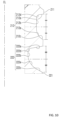
- FIG 9 is a view for describing cases of machining an external screw part of the dental implant according to the present invention using bits having different shapes
- FIG 10 is an enlarged view of a portion of the external screw part according to the present invention.
- the external screw part 200 may include an external top thread section 210 and an external bottom thread section 220.
- the external screw part 200 may include the external top thread section 210 machined down to a predetermined section downward from a top of an outer peripheral surface of the dental implant 1000 so that first crests 211 having a first height and first valleys 212 having a first depth are formed by a first bit B 1.
- the external screw part 200 may include the external bottom thread section 220 machined below the external top thread section 210 so that second crests 221 having a second height and second valleys 222 having a second depth are formed by a second bit B2 having a machining surface shape and a width that are different from a machining surface shape and a width of the first bit B 1.
- first height of the first crests 211 may be formed to be lower than the second height of the second crests 221.
- the first depth of the first valleys 212 may be formed to be shallower than the second depth of the second valleys 222.
- H1 and H2 may be a thread valley depth (or thread crest height) of threads formed in the external top thread section 210 by the first bit B1
- H2 may be a thread valley depth (or thread crest height) of threads formed in the external bottom thread section 220 by the second bit B2.
- a bit In a conventional process of an implant thread machining, a bit enters a bottom of a machining target surface of an implant while an implant base material is rotated, and the bit is moved upward along a determined constant movement trajectory so as to perform the thread machining.
- a thread height may be adjusted by adjusting an entry depth of the bit into the machining target surface of the implant base material.
- the threads of the external bottom thread section 220 that have a large thread valley depth H2 (or a large crest height) are machined by entering the second bit B2 into the implant base material.
- the second bit B2 is replaced with the first bit B 1, and the machining of the threads of the external top thread section 210 that have a small thread valley depth H1 (or a small crest height) is performed.
- a thread non-machining section H in which the thread machining is not performed is formed up to a predetermined depth from the topmost of the dental implant 1000, the external top thread machining of the dental implant 1000 by the first bit B 1 is not performed up to the topmost portion of the dental implant 1000, and the thread machining may be finished at a point spaced apart downward by a predetermined distance from the topmost of the dental implant 1000.
- a difference in shape of a machining surface of each end portion of the second bit B2 performing the external bottom thread machining of the dental implant 1000 and the first bit B1 performing the external top thread machining of the dental implant 1000 is required to be accompanied.
- the thread machining is performed by varying the shape and width of the end portion machining surfaces of the first bit B1 and the second bit B2 that are configured to machine the external top thread section 210 and the external bottom thread section 220, respectively. Therefore, a thread structure in which the pitch P of each thread is the same and the crest width W (see FIG 2 ) of each thread is the same although the heights of the crests 211 and 221 formed at the external top thread section 210 and the external bottom thread section 220, respectively, are different from each other may be formed.
- the dental implant 1000 of the present invention may be formed such that the bottom of the external top thread section 210 is positioned downward to a lower side position by 2 to 4 threads from a bottom surface of the boring part 130 inside the dental implant 1000 as a starting point when the external top thread section 210 having the threads that have small heights (or valley depths) is formed.
- the first valleys 212 of the external top thread section 210 and the second valleys 222 of the external bottom thread section 220 may include first curved parts 212d and 222d connecting from upper portions 212a and 222a of the valleys to side portions 212b and 222b thereof and second curved parts 212e and 222e connecting from the side portions 212b and 222b of the valleys to lower portions 212c and 222c thereof.
- first curved parts and the second curved parts are formed at corner sides of the valleys 212 and 222, when the dental implant 1000 is implanted into the alveolar bone, stress concentrated on the corner sides of the valleys 212 and 222 can be distributed, and stability to protect against fracture of the dental implant 1000 can be improved.
- the first valleys 212 of the external top thread section 210 and the second valleys 222 of the external bottom thread section 220 may be formed to be horizontally asymmetrical about a virtual line that is perpendicular to the axis CL and passes through a center of a width of the valleys.
- a curvature of the first curved parts 212d and 222d may be formed to be larger than a curvature of the second curved parts 212e and 222e.
- a lower portion of the valleys 212 and 222 is formed to be relatively gentler than an upper portion of the valleys 212 and 222, and accordingly, when the dental implant 1000 enters the alveolar bone, the second curved parts 212e and 222e having a relatively gentler slope may make it relatively easy to implant the dental implant 1000 into the alveolar bone, and convenience of the implantation can be improved.
- the alveolar bone in the valleys 212 and 222 is pressed from above by the first curved parts 212d and 222d having a relatively steeper slope, stability of the implantation can be improved.
- a cutting edge 223 formed to be partially cut may be provided at a bottom of the outer peripheral surface of the dental implant 1000 to improve stability of implantation of the dental implant 1000, and the cutting edge 223 may include a reverse helical section formed in the opposite direction of a helical direction of the crests 211 and 221.
- the cutting edge 223 may include a helical section formed in the helical direction of the crests 211 and 221. Also, the cutting edge 223 may include a linear section in which a portion of the cutting edge 223 is parallel to the axis CL. Here, the portion of the cutting edge 223 having the linear section may be disposed at the bottom of the cutting edge 223.
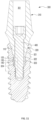
- FIG 11 is a cross-sectional view of a dental implant assembly according to the present invention
- FIG 12 is a front view of an abutment according to the present invention
- FIG 13 is an enlarged view of a portion of FIG 11 .
- a dental implant assembly may include the dental implant 1000, an abutment 300, and a fastening screw 400.
- the abutment 300 may be coupled to the dental implant 1000 to support a prosthesis and may have a fastening screw insertion hole 301 formed therein which extends from a top of the abutment 300 to a bottom thereof.
- the abutment 300 includes an upper side part 310 configured to protrude to an outer portion of the dental implant 1000 and have a prosthesis attached thereto and a lower side part 320 disposed below the upper side part 310 and partially inserted into the internal groove 100 of the dental implant 1000.
- the lower side part 320 may include a tapered insertion part 321, a rotation preventing part 322, a cylindrical part 323, and a holding part 324, sequentially from an upper side.
- the tapered insertion part 321 may be inserted into and seated on the upper side inclined part 110 of the dental implant 1000 and may be formed in a shape that corresponds to the upper side inclined part 110.
- the rotation preventing part 322 may be disposed below the tapered insertion part 321 and inserted into the polygonal part 120 of the dental implant 1000 to constrain rotation of the abutment 300 relative to the dental implant 1000.
- the rotation preventing part 322 may be formed in a shape that corresponds to the polygonal part 120.
- the cylindrical part 323 may be disposed below the rotation preventing part 322 and may be formed in a substantially cylindrical shape.
- the cylindrical part 323 may have at least one portion inserted into the circular vertical part 140 of the dental implant 1000. More specifically, at least one portion of the cylindrical part 323 may be inserted into the circular vertical part 140 together with the holding part 324.
- the holding part 324 may be disposed below the cylindrical part 323 and may be, when the abutment 300 is inserted into the dental implant 1000, elastically forcibly fitted into an inner peripheral surface of the circular vertical part 140 and temporarily fix the abutment 300 to the dental implant 1000. That is, the holding part 324 is for temporarily fixing the abutment 300 to the inner peripheral surface of the circular vertical part 140.
- the holding part 324 may be provided as a plurality of holding parts 324 that are disposed to be spaced apart along a periphery of the bottom of the cylindrical part 323. Also, the holding part 324 may be provided as a single holding part 324 that is formed to form a closed loop along the periphery of the bottom of the cylindrical part 323. Examples of a closed loop shape may include a circular shape, an elliptical shape, a polygonal shape, and the like.
- the fastening screw 400 may have a lower portion screw-coupled to the internal screw part 150 of the dental implant 1000 in a state in which the fastening screw 400 is inserted into the fastening screw insertion hole 301 of the abutment 300, and in this way, the fastening screw 400 may firmly fix the abutment 300 temporarily fixed to the dental implant 1000.
- inclination of an upper side inclined part of an internal groove of an implant relative to an axis is set to a specific range to increase an area of contact with an abutment, which is advantageous for stress distribution and prevents a top thickness of the implant from being excessively thin, thereby improving the strength of the implant.
- the bottommost depth of a circular vertical part of the internal groove of the implant to which an external force is applied through the abutment is formed to be relatively deep to be half or more of the overall depth of the internal groove. In this way, a distance from the upper side inclined part to which an external force is applied through the abutment is increased, which facilitates internal stress distribution and may be advantageous for improving the strength of the implant.
- a thickness of the circular vertical part is formed to be thick relative to the maximum outer diameter of the implant, which may be advantageous for improving the strength of the implant.
- first curved part is formed at an upper side corner of valleys of external threads
- second curved part is formed at a lower side corner thereof
- a lower portion of the valleys is formed to be relatively gentler than an upper portion of the valleys, and accordingly, when the implant enters the alveolar bone, the second curved part having a relatively gentler slope may make it relatively easy to implant the implant into the alveolar bone, and convenience of the implantation can be improved.
Landscapes
- Health & Medical Sciences (AREA)
- Oral & Maxillofacial Surgery (AREA)
- Orthopedic Medicine & Surgery (AREA)
- Dentistry (AREA)
- Epidemiology (AREA)
- Life Sciences & Earth Sciences (AREA)
- Animal Behavior & Ethology (AREA)
- General Health & Medical Sciences (AREA)
- Public Health (AREA)
- Veterinary Medicine (AREA)
- Dental Prosthetics (AREA)
Applications Claiming Priority (2)
| Application Number | Priority Date | Filing Date | Title |
|---|---|---|---|
| KR20230133730 | 2023-10-06 | ||
| KR1020240090657A KR102870107B1 (ko) | 2023-10-06 | 2024-07-09 | 치과용 임플란트 및 이를 포함하는 치과용 임플란트 조립체 |
Publications (1)
| Publication Number | Publication Date |
|---|---|
| EP4534041A1 true EP4534041A1 (en) | 2025-04-09 |
Family
ID=93013886
Family Applications (1)
| Application Number | Title | Priority Date | Filing Date |
|---|---|---|---|
| EP24204726.4A Pending EP4534041A1 (en) | 2023-10-06 | 2024-10-04 | Dental implant and dental implant assembly having the same |
Country Status (5)
| Country | Link |
|---|---|
| US (1) | US20250205020A1 (ko) |
| EP (1) | EP4534041A1 (ko) |
| KR (1) | KR20250153152A (ko) |
| CN (1) | CN119770205A (ko) |
| WO (1) | WO2025075314A1 (ko) |
Families Citing this family (1)
| Publication number | Priority date | Publication date | Assignee | Title |
|---|---|---|---|---|
| USD1112747S1 (en) * | 2023-10-06 | 2026-02-10 | Osstem Implant Co., Ltd. | Dental implant |
Citations (5)
| Publication number | Priority date | Publication date | Assignee | Title |
|---|---|---|---|---|
| US20080261175A1 (en) * | 2007-04-23 | 2008-10-23 | Nobel Biocare Services Ag | Dental implant |
| US20160120627A1 (en) * | 2014-10-29 | 2016-05-05 | Vogul, S.L.U. | Dental implant |
| WO2022145798A1 (ko) * | 2020-12-30 | 2022-07-07 | 오스템임플란트 주식회사 | 치과용 임플란트 |
| KR20230133730A (ko) | 2022-03-11 | 2023-09-19 | 주식회사 에이치엘클레무브 | Can 통신을 수행하는 방법 및 장치 |
| KR20240090657A (ko) | 2015-06-29 | 2024-06-21 | 아브락시스 바이오사이언스, 엘엘씨 | 나노입자 mTOR 억제제 조합 요법을 사용하여 고형 종양을 치료하는 방법 |
Family Cites Families (5)
| Publication number | Priority date | Publication date | Assignee | Title |
|---|---|---|---|---|
| US20230059997A1 (en) * | 2017-10-11 | 2023-02-23 | Evollution Ip Holdings, Inc. | Dental implant with improved stabilization thread form and cutting elements |
| KR102118038B1 (ko) * | 2019-10-11 | 2020-06-09 | (주)아름덴티스트리 | 치과용 임플란트 픽스쳐 |
| KR102304075B1 (ko) * | 2020-12-30 | 2021-09-24 | 오스템임플란트 주식회사 | 치과용 임플란트 픽스쳐 |
| KR102698004B1 (ko) * | 2021-12-30 | 2024-08-23 | 오스템임플란트 주식회사 | 치과용 임플란트 조립체 |
| KR102680039B1 (ko) * | 2021-12-30 | 2024-07-02 | 오스템임플란트 주식회사 | 치과용 임플란트 |
-
2024
- 2024-09-06 WO PCT/KR2024/013520 patent/WO2025075314A1/ko active Pending
- 2024-09-30 CN CN202411387082.XA patent/CN119770205A/zh active Pending
- 2024-10-04 EP EP24204726.4A patent/EP4534041A1/en active Pending
- 2024-10-06 US US18/907,531 patent/US20250205020A1/en active Pending
-
2025
- 2025-10-01 KR KR1020250143819A patent/KR20250153152A/ko active Pending
Patent Citations (5)
| Publication number | Priority date | Publication date | Assignee | Title |
|---|---|---|---|---|
| US20080261175A1 (en) * | 2007-04-23 | 2008-10-23 | Nobel Biocare Services Ag | Dental implant |
| US20160120627A1 (en) * | 2014-10-29 | 2016-05-05 | Vogul, S.L.U. | Dental implant |
| KR20240090657A (ko) | 2015-06-29 | 2024-06-21 | 아브락시스 바이오사이언스, 엘엘씨 | 나노입자 mTOR 억제제 조합 요법을 사용하여 고형 종양을 치료하는 방법 |
| WO2022145798A1 (ko) * | 2020-12-30 | 2022-07-07 | 오스템임플란트 주식회사 | 치과용 임플란트 |
| KR20230133730A (ko) | 2022-03-11 | 2023-09-19 | 주식회사 에이치엘클레무브 | Can 통신을 수행하는 방법 및 장치 |
Also Published As
| Publication number | Publication date |
|---|---|
| KR20250153152A (ko) | 2025-10-24 |
| WO2025075314A1 (ko) | 2025-04-10 |
| US20250205020A1 (en) | 2025-06-26 |
| CN119770205A (zh) | 2025-04-08 |
Similar Documents
| Publication | Publication Date | Title |
|---|---|---|
| US6431869B1 (en) | Reduced friction screw-type dental implant | |
| KR102304081B1 (ko) | 임플란트용 어버트먼트, 및 이 어버트먼트와 픽스쳐의 결합구조 | |
| US9707059B2 (en) | Self-clearing self-cutting implant | |
| EP1900340B1 (en) | Implant | |
| EP4534041A1 (en) | Dental implant and dental implant assembly having the same | |
| US20190167324A1 (en) | Method of making a self-cleaning self-cutting implant | |
| EP2946746A1 (en) | Dental implant and kit including said dental implant | |
| US20070053765A1 (en) | Thread on a bone screw | |
| WO2009066935A1 (en) | A dental implant drill having a multi-step structure | |
| KR102118038B1 (ko) | 치과용 임플란트 픽스쳐 | |
| US20160100916A1 (en) | Implant arrangement with an internal socket for a turning tool | |
| KR102304071B1 (ko) | 치과용 임플란트 픽스쳐 | |
| JP2011237034A (ja) | コンクリート用タップねじ | |
| KR102059302B1 (ko) | 치과용 임플란트 시스템 | |
| EP0260446A1 (en) | Contoured dental posts | |
| KR102870107B1 (ko) | 치과용 임플란트 및 이를 포함하는 치과용 임플란트 조립체 | |
| EP4272691B1 (en) | Dental implant | |
| KR102698004B1 (ko) | 치과용 임플란트 조립체 | |
| KR101731542B1 (ko) | 임플란트용 픽스쳐 | |
| EP1696815B1 (en) | Implant | |
| KR102907413B1 (ko) | 치과용 임플란트 표면처리방법 및 그 방법에 의해 표면 처리된 치과용 임플란트 | |
| KR102304065B1 (ko) | 치과용 임플란트 픽스쳐 | |
| EP4512366A1 (en) | Abutment for dental implants | |
| AU2022292636B2 (en) | Bodkin style broaching tip for a self-punching bone anchor | |
| WO2025229696A1 (en) | A dental implant with a gradual change in thread morphology |
Legal Events
| Date | Code | Title | Description |
|---|---|---|---|
| PUAI | Public reference made under article 153(3) epc to a published international application that has entered the european phase |
Free format text: ORIGINAL CODE: 0009012 |
|
| STAA | Information on the status of an ep patent application or granted ep patent |
Free format text: STATUS: REQUEST FOR EXAMINATION WAS MADE |
|
| 17P | Request for examination filed |
Effective date: 20241004 |
|
| AK | Designated contracting states |
Kind code of ref document: A1 Designated state(s): AL AT BE BG CH CY CZ DE DK EE ES FI FR GB GR HR HU IE IS IT LI LT LU LV MC ME MK MT NL NO PL PT RO RS SE SI SK SM TR |