EP4534192A2 - Installation et procédé d'urée à strippage thermique - Google Patents
Installation et procédé d'urée à strippage thermique Download PDFInfo
- Publication number
- EP4534192A2 EP4534192A2 EP24219784.6A EP24219784A EP4534192A2 EP 4534192 A2 EP4534192 A2 EP 4534192A2 EP 24219784 A EP24219784 A EP 24219784A EP 4534192 A2 EP4534192 A2 EP 4534192A2
- Authority
- EP
- European Patent Office
- Prior art keywords
- stream
- carbamate
- condenser
- solution
- urea
- Prior art date
- Legal status (The legal status is an assumption and is not a legal conclusion. Google has not performed a legal analysis and makes no representation as to the accuracy of the status listed.)
- Pending
Links
Images

Classifications
-
- C—CHEMISTRY; METALLURGY
- C07—ORGANIC CHEMISTRY
- C07C—ACYCLIC OR CARBOCYCLIC COMPOUNDS
- C07C273/00—Preparation of urea or its derivatives, i.e. compounds containing any of the groups, the nitrogen atoms not being part of nitro or nitroso groups
- C07C273/02—Preparation of urea or its derivatives, i.e. compounds containing any of the groups, the nitrogen atoms not being part of nitro or nitroso groups of urea, its salts, complexes or addition compounds
- C07C273/04—Preparation of urea or its derivatives, i.e. compounds containing any of the groups, the nitrogen atoms not being part of nitro or nitroso groups of urea, its salts, complexes or addition compounds from carbon dioxide and ammonia
-
- B—PERFORMING OPERATIONS; TRANSPORTING
- B01—PHYSICAL OR CHEMICAL PROCESSES OR APPARATUS IN GENERAL
- B01D—SEPARATION
- B01D5/00—Condensation of vapours; Recovering volatile solvents by condensation
- B01D5/0057—Condensation of vapours; Recovering volatile solvents by condensation in combination with other processes
- B01D5/0075—Condensation of vapours; Recovering volatile solvents by condensation in combination with other processes with heat exchanging
-
- B—PERFORMING OPERATIONS; TRANSPORTING
- B01—PHYSICAL OR CHEMICAL PROCESSES OR APPARATUS IN GENERAL
- B01J—CHEMICAL OR PHYSICAL PROCESSES, e.g. CATALYSIS OR COLLOID CHEMISTRY; THEIR RELEVANT APPARATUS
- B01J3/00—Processes of utilising sub-atmospheric or super-atmospheric pressure to effect chemical or physical change of matter; Apparatus therefor
- B01J3/02—Feed or outlet devices therefor
-
- B—PERFORMING OPERATIONS; TRANSPORTING
- B01—PHYSICAL OR CHEMICAL PROCESSES OR APPARATUS IN GENERAL
- B01J—CHEMICAL OR PHYSICAL PROCESSES, e.g. CATALYSIS OR COLLOID CHEMISTRY; THEIR RELEVANT APPARATUS
- B01J3/00—Processes of utilising sub-atmospheric or super-atmospheric pressure to effect chemical or physical change of matter; Apparatus therefor
- B01J3/04—Pressure vessels, e.g. autoclaves
- B01J3/042—Pressure vessels, e.g. autoclaves in the form of a tube
Definitions
- the invention pertains to the production of urea and in particular to a urea plant and process using a high pressure stripper of the thermal stripping type (also known as the self-stripping type).
- Urea production plants are often of the ⁇ total recycle type'.
- the urea synthesis stream from the high pressure reaction zone which contains urea, water, ammonia, and ammonium carbamate is expanded and subjected to decomposition of the carbamate to give a purified urea solution and a gas stream containing NH 3 and CO 2 .
- the gas stream is subjected to condensation to form a carbamate solution which solution is pumped back to the high pressure reaction zone.
- This recycled carbamate solution contains water to avoid the solidification of ammonium carbamate.
- water is a by-product in the urea formation reaction
- the recycle of water is undesirable and it is desired to minimize the water content of the carbamate recycle stream. It is generally desired to minimize the specific water amount introduced into the HP reaction zone from the low and medium pressure sections.
- the HP stripper and the HP carbamate condenser are each typically shell-and-tube heat exchangers with a tube bundle that contains thousands of tubes.
- the HP reactor is often a vertical vessel with trays.
- the stripper is typically a falling-film shell-and-tube heat exchanger with urea solution in the tubes and strip-gas flowing up.
- the HP carbamate condenser is typically a shell-and-tube heat exchanger with a horizontal or vertical tube bundle, with straight or U-shaped tubes, and with cooling fluid or process medium (process fluids) in the tubes.
- the strip gas is CO 2 feed; the N/C ratio in the reactor is about 3.0 and the N/C ratio of the stripped urea solution is relatively low.
- the HP reactor typically has separate outlets for inert gases sent to a HP scrubber and for urea synthesis solution sent to the HP stripper.
- the urea reactor operates at a relatively high N/C ratio of above 3.0, in plants of the 'Snamprogetti' design often at N/C ratio of 3.2 - 3.6, e.g. 3.2 - 3.4.
- the reactor is operated at e.g. 150 to 160 bar.
- the stripped urea solution from a thermal stripper has a relatively high N/C ratio and is supplied to a medium pressure (MP) recovery section comprising an MP decomposer, a MP carbamate condenser and a separate MP ammonia condenser.
- the MP decomposer gives urea solution that is sent to the LP recovery section and a gas stream containing CO 2 and relatively high amounts of NH 3 .
- the gas stream is subjected to condensation in the MP carbamate condenser to give carbamate solution and remaining NH 3 gas.
- the remaining NH 3 gas from the MP condenser is subjected to condensation in the MP ammonia condenser.
- Condensed ammonia and carbamate solution are separately pumped back from the MP section to the HP section, typically as two different liquid streams with different temperatures and using different pumps.
- An example urea process of the thermal stripping type is the 'Snamprogetti' urea process illustrated in Ullmann's Encyclopaedia of Industrial Chemistry, Chapter Urea, 2010, Figure 25.
- the high pressure (HP) reactor has one outlet and the entire urea synthesis stream from the reactor is supplied to the HP stripper which is of the thermal stripping type.
- the inert gases pass through the HPCC, whereby oxygen comprised in the inert gases provides for corrosion protection of the HPCC, and the inert gases are separated from the HP condensate in a HP carbamate separator and supplied as gas stream to the MP recovery section where they are vented from an ammonia scrubber arranged downstream of the ammonia condenser. In this way, the vented inert gases do not contain much NH 3 despite the relatively high N/C ratio of the urea solution in the thermal stripper.
- the MP recovery section typically operates at 18 bar in the ⁇ Snamprogetti' design.
- a flashing step and/or N/C measurement is used for the second stream.
- the process involves determining the N/C ratio of the second stream. Determining the N/C ratio is advantageously in particular simple in preferred embodiments wherein the second stream consists of degassed liquid. Very advantageously in these embodiments with a degassed second stream consists of liquid, instead of a two-phase gas/liquid fluid stream, and the N/C ratio can accordingly be conveniently measured.
- the flash vapor is supplied to the first MP recovery section, in particular directly or indirectly to an ammonia condenser of the first MP recovery section, to condense as ammonia condensate which is recycled to the synthesis section using an ammonia pump.
- an ammonia condenser of the first MP recovery section to condense as ammonia condensate which is recycled to the synthesis section using an ammonia pump.
- the first stream preferably comprises both vapor and liquid and preferably is a two-phase fluid.
- the second stream preferably consists essentially of liquid.
- the separation involves degassing the second stream.
- the first stream total stream, including both gas and liquid in case of a two-phase fluid
- Such separation can be done at high pressure based on e.g. gravimetric density separation.
- the first stream is degassed in the HP separator, and the degassed first stream is supplied to the thermal stripper.
- the process involves determining the N/C ratio of the first stream.
- the first stream is at least in part, such as entirely, e.g. for at least 90 wt.% of the liquid phase, sent to the HP stripper of the thermal stripping type.
- the stripped urea solution from the thermal stripper is at least in part, such as entirely, such as for at least 90 wt.%, sent to the first MP recovery section.
- the second MP recovery section receives at least 95 wt.% or at least 99 wt.% of the second stream as provided by the high pressure separator.
- the second MP recovery section preferably receives non-stripped urea solution from the HP reactor as said second stream.
- the preferred MP adiabatic flash unit receives at least a part, preferably all, of the second stream, preferably the degassed second stream, and has a first outlet for flash vapor and a second outlet for flashed urea solution.
- the MP flash unit is preferably adiabatic in that it is preferably not actively heated. This has the advantage that the endothermic carbamate decomposition reaction proceeds hardly or only to a limited extent such that the flash vapor has a relatively low CO 2 content.
- the adiabatic flash provides for low water evaporation and an advantageously low water content of the flash vapor.
- the flash vapor comprises at least 90 wt.% NH 3 or is essentially pure NH 3 .
- the MP adiabatic flash unit preferably operates at a pressure of at least 20 bar (absolute), for instance at a pressure in the range of 20 to 60 bar (absolute), e.g. 25 to 40 bar, such as at 25 to 35 bar or e.g. at 30 to 40 bar.
- the pressure of the MP adiabatic flash step can advantageously be used to adjust the composition of the recycle carbamate streams.
- the urea solution at the outlet of the MP flash unit for instance comprises 15-25 mol.% NH 3 (both free and as carbamate) and 5-15 mol.% CO 2 (both free and as carbamate), for instance at a pressure of 20 - 30 bar.
- the carbamate condenser and the ammonia condenser of the existing first MP recovery section usually have a margin to receive vapor from the adiabatic flash.
- the pressure of the adiabatic flash can be used to adjust the amount of flashed gas.
- the second MP decomposer has an inlet for the preferably flashed urea solution or for the second stream (if the preferred adiabatic flash is not used), an outlet for vapor and an outlet for urea solution.
- the second MP decomposer comprises typically a heat exchanger, preferably comprises a shell-and-tube heat exchanger, and preferably uses steam as heating fluid.
- the second MP decomposer comprises e.g. a vertical straight tube shell-and-tube heat exchanger having a rectifier on top.
- the rectifier comprises a packing allowing for contact between incoming, downward falling liquid and the upward moving gas.
- the gas outlet is preferably at the top.
- the liquid inlet is preferably at an upper part of the rectifier.
- the second MP decomposer is operated e.g. at 15 to 25 bar.
- the first and second MP decomposer can advantageously be operated at different pressures.
- the second MP decomposer is e.g. operated at a higher pressure than the first MP decomposer, e.g. at least 1.0 bar or at least 5.0 bar higher, e.g. 5 to 15 bar higher. This may contribute to a relatively high condensation temperature in the second MP carbamate condenser.
- the vapor from the second MP decomposer is supplied to the second MP carbamate condenser which has an outlet for carbamate solution.
- the second MP carbamate condenser may be provided as one or more units. For instance, it is provided as two shell-and-tube heat exchangers.
- the second MPCC comprises e.g. a first heat exchanger for indirect heat exchange against urea solution that needs to be heated, e.g. for water evaporation, and a second heat exchanger against cooling water.
- the second MP decomposer and the second MP carbamate condenser are preferably operated at substantially the same pressure. A higher condensation temperature is in such embodiments desired for the first heat exchanger.
- the carbamate solution is recycled, directly or indirectly, to the HP synthesis section, e.g. to the HPCC of a thermal stripping plant, in particular to the process medium side of such a HPCC, e.g. the tube side of a kettle-type HPCC.
- This recycle typically involves pumping of the carbamate solution using a HP carbamate pump.
- the second MP recovery section further preferably comprises an inlet for a CO 2 feed gas stream, such that MP CO 2 feed is supplied directly or indirectly to the second MP carbamate condenser where it is subjected to condensation with ammonia (originating from the second stream, e.g. from the second MP decomposer) to form a carbamate solution.
- the MP CO 2 feed is supplied to a MP CO 2 stripper comprised in the second MP recovery section.
- the urea solution from the MP decomposer is subjected to stripping (counter-current contact with the CO 2 gas flow) to give a vapor stream and a MP stripped solution.
- the stripping in the MP CO 2 stripper is preferably adiabatic.
- the MP CO 2 stripper comprises for instance a packed bed adapted for counter-current contacting of gas and liquid.
- the first stream has for instance an N/C ratio in the range 3.3-3.6 at the reactor outlet and at the outlet of the HP separator.
- the carbamate solution from the second MP carbamate condenser contains 50-60 mol%, e.g. 55 mol.% NH 3 (both free and as carbamate), 20-25, e.g. 22 mol.% CO 2 (both free and as carbamate), and 20-25 mol%, e.g. 23 mol% H 2 O.
- the solution e.g. has a pressure of 17-18 bar.
- the carbamate solution from the first MP carbamate condenser has a water content of 23-27 wt.%, e.g. 25 wt.%
- the carbamate solution from the second MP carbamate condenser has a water content of 18-22 wt.%, for instance 20 wt.%.
- the purified urea solution from the first MP recovery section and from the second MP recovery section are both sent to a LP recovery section of the urea plant, e.g. to two separate LP recovery sections or to the same LP recovery section.
- the one or more LP recovery sections typically comprise a LP decomposer and a LP carbamate condenser.
- the LP carbamate solution from the LP carbamate condenser is e.g. supplied to the first and/or second MP carbamate condenser.
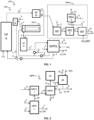
- Figure 1 schematically illustrates an example process scheme according to the invention which does not limit the invention and does not limit the claims.
- reference numbers as shown in Fig. 1 are used merely for convenience and without limiting the invention in any way.
- the inventive urea production process is generally carried out in a urea production plant (UPP) of the thermal stripping type.
- the plant comprises a high pressure (HP) synthesis section (HPS) and a first and a second medium pressure (MP) recovery section (MPR1, MPR2).
- the first and second MP recovery section receive a urea-comprising stream from the HP synthesis section and yield a MP urea solution which is typically further processed in a LP recovery section to give a LP urea solution which is for instance further concentrated in an evaporation section to form a urea melt.
- the urea melt is often sent to a finishing section where solid urea product is formed, e.g. a granulator or prilling tower.
- the HP reaction zone is e.g. provided by one or more HP urea reactors. If two or more HP urea reactors are used, these are e.g. arranged in parallel or in series.
- the one or more HP reactors are typically vertical bubbling columns with trays.
- the reactor is e.g. operated at 180-200°C, e.g. 185-195°C, and/or at a pressure of at least 140 bar, e.g. 140-160 bar or 150-160 bar.
- the reactor is operated e.g. with an N/C ratio in the range of 3.00 to 3.40, e.g. in the range of 3.1 to 3.2.
- the urea production process for instance involves supplying oxygen (O 2 ) for passivation purposes into the HP reaction zone (HPR), for example in an amount of at least 0.010 vol.% based on fresh CO 2 feed, e.g. by introducing air in an amount of at least 0.10 vol% and typically less than 1.0 vol.% relative to fresh CO 2 feed.
- the passivation air or oxygen is e.g. supplied as part of the CO 2 feed.
- the passivation air or oxygen is e.g. supplied directly to the HP urea reactor.
- the thermal stripper is operated at e.g. 200-210°C, these temperatures indicating the urea solution outlet temperature.
- the HP carbamate condenser is preferably a shell-and-tube heat exchanger, more preferably a heat exchanger with a horizontal U-shaped tube bundle.
- the HPCC is configured for operation with liquid as continuous phase on the process side.
- the HP carbamate condenser is preferably of the kettle-type with a horizontal U-shaped tube bundle, having an inlet for receiving gas to be condensed inside the tubes and an inlet for receiving cooling fluid in the shell.
- Other types of HP carbamate condenser are also possible, such as with a vertical U-shaped tube bundle, or with a horizontal U-shaped tube bundle and with an inlet for receiving gas to be condensed in the shell and an inlet for receiving cooling fluid in the tubes.
- the HPCC additionally receives medium pressure carbamate solution from the first MP recovery section in the process side, such as in the tubes for a kettle-type condenser.
- the HP process fluid stream (4) from the HPCC contains carbamate solution and inerts and is supplied to a carbamate separator (CSp) operated at high pressure and configured for gas/liquid separation to give a liquid stream (5) and a gas stream (6).
- the liquid carbamate stream (5) is supplied to the reactor, typically using an ammonia-driven ejector (Ej) .
- the gas (6) from the carbamate separator (CSp) contains inerts and ammonia and is supplied preferably to the first MP recovery section, e.g. to a bottom part of a MP decomposer. Supplying the gas (6) to the first MP recovery section (MPR1) is particularly advantageous in embodiments wherein the MP flash unit (MPF) receives degassed urea solution.
- MPF MP flash unit
- the HP synthesis section further comprises a separator (HPLS), in particular a high pressure separator, more in particular a high pressure liquid separator.
- the separator is operated at high pressure.
- the separator is for instance a dedicated unit or is arranged inside a reactor vessel. If two or more reactors are used in series, the separator is preferably arranged in the most downstream reactor.
- a separator provided as a dedicated unit, is preferably arranged downstream of the reactor.
- the separator is preferably arranged at a downstream part of the reaction zone.
- the separator preferably receives reaction mixture wherein the conversion (urea formation) is already at least 90% completed relative to the total conversion achieved in the HP synthesis section.
- the reaction mixture at the inlet of the separator comprises e.g. at least 30 wt.% urea, such as 30 - 35 wt.% urea.
- no NH 3 and/or no gaseous components are removed from the reaction mixture in the reaction zone prior to the separation in the HP separator.
- the inventive urea production process involves separating the reaction mixture from the reaction zone (HPR) at high pressure in said separator (HPLS) into a first stream, e.g. an ammonia-rich first stream (S1), and a second stream (S2).
- the first and second stream both contain a liquid phase; this liquid phase contains urea.
- the ammonia-rich first stream (S1) preferably has a lower gravimetric density than the second stream (S2), at the separation.
- the separation can be based for instance on gravimetric density separation.
- the first stream (S1) has for instance a higher concentration of ammonia than the second stream (S2) based on the total volume of the two streams (including gas and liquid in case of two phase fluid streams).
- the HP separator is arranged at a downstream end of the reaction zone.
- the process involves determining the N/C ratio of the second stream.
- the process involves determining the N/C ratio of the degassed stream from the HP separator.
- Determining the N/C ratio is advantageously in particular simple in preferred embodiments wherein the second stream consists of degassed liquid.
- the N/C ratio of the liquid phase comprised in the first stream can also be determined as it is substantially the same as the measured N/C ratio of the second stream. This can be used for better controlling the operation of the synthesis section, such as the reactor and the thermal stripper, and the first MP recovery section; such as during start-up of the plant.
- Information about the N/C ratio in the liquid phase is useful because the urea formation reaction takes place only in the liquid phase in the reactor.
- the plant comprises an N/C meter in the flow line for the degassed stream, preferably in the flow line for the degassed second stream to the MP recovery section.
- a small part of the HP degassed liquid stream is drawn off and supplied to the N/C meter.
- N/C meters for liquid urea reactor effluent are known in the art and use e.g. the relationship (correlation) between liquid density and N/C ratio e.g. at fixed temperature and pressure.
- the N/C meter is for example based on measuring the liquid density using e.g. a Coriolis density measurement, a nucleonic density gauge, or e.g. vibrating element technology to measure liquid density. Other methods can also be employed.
- Information about the N/C ratio of the first stream supplied to the thermal stripper is in particular useful in the inventive process wherein the operation of the first and second recovery section, e.g. the preferred adiabatic flash, provides for increased flexibility for optimizing the urea yield.
- the installation of the N/C meter ensures a stable plant operation with lower energy consumption and lower ammonia emission, especially because the two MP recovery sections typically generate carbamate solutions with different N/C ratios.
- first MP recovery section comprises a first MP decomposer (MPD-1), a first MP carbamate condenser (MPCC-1), and an ammonia condenser (AC), as well as preferably a MP separation column (MPSC) and an ammonia receiver (AR).
- MPD-1 MP decomposer
- MPCC-1 MP carbamate condenser
- AC ammonia condenser
- MPSC MP separation column
- AR ammonia receiver
- the condensation can be carried out using one or more heat exchanging units and using as cooling fluid e.g. cooling water and/or urea solution that needs to be heated.
- the first MP carbamate condenser (MPCC-1) is e.g. provided, as a MP condenser/pre-evaporator for indirect heat exchange against urea solution to be heated, optionally with a further downstream MP condenser for condensing at least a part of the non-condensed gases from the first MP carbamate condenser (MPCC-1).
- the downstream MP condenser operates e.g. with cooling water.
- the MP condensate (19) is supplied to the bottom of the column and heated, and feed liquid NH 3 is supplied to the top of the column.
- the column comprises trays.
- an aqueous stream is supplied just below the top of the column.
- the gas stream (21) from the top of the separation column contains only NH 3 and inerts. This gas stream (21) is preferably supplied to the ammonia condenser (AC).
- the bottom product of the ammonia-carbamate separation column (MPSC) is the MP carbamate solution (8) and contains relatively much NH 3 and water.
- the non-condensed gas stream from the first MP carbamate condenser (MPCC-1) is preferably after purification to purer ammonia gas, supplied to a (first) ammonia condenser (AC), which is a heat exchanger preferably using cooling water as cooling fluid.
- the ammonia condenser is preferably operated at a temperature in the range of 20 to 50°C.
- the process involves expanding the preferably degassed second stream (S2) from high pressure to medium pressure in the second MP recovery section in the preferred MP adiabatic flashing step (MPF) as discussed to give a gaseous stream (11) (flash vapor) and a flashed MP urea solution (12).
- the MP flash is carried out at a pressure in the range of 25 to 40 bar.
- the second MP decomposer operates at a pressure slightly lower than the MP flash unit, e.g. 1 bar lower.
- the plant comprises an expansion valve between the MP adiabatic flash unit and the second MP decomposer.
- non-condensed gases (20) have low inert content such that they can be condensed and scrubbed in the LP recovery section to give an LP carbamate stream with low water content that is recycled directly or indirectly to the HP synthesis section.
- the carbamate solution (15) from the second MP carbamate condenser (MPCC2) is for instance pumped to the HP carbamate condenser using preferably a dedicated carbamate pump, for instance if MPCC-2 operates at higher pressure than MPCC-1.
- the plant comprises, as separate pumps, an ammonia HP pump, a carbamate pump of the first MP recovery section, and a carbamate pump of the second MP recovery section, for pumping these three streams separately to the HP section.
- an ammonia HP pump for pumping these three streams separately to the HP section.
- a carbamate pump of the first MP recovery section for pumping these three streams separately to the HP section.
- This in particular allows the streams to have different temperatures and/or different pressures in the MP range, which contributes advantageously to lower water content of the recycle stream (15).
- the carbamate solution (15) bypasses the MP separation column (MPSC) and is supplied to the carbamate pump used in the first recovery section (MPR1) for pumping the carbamate solution (8) to the HP section.
- MPSC MP separation column
- MPR1 first recovery section
- the invention also pertains to a urea plant (urea production plant) which preferably suitable for the inventive processes. Preferences for and details of the plant, units and connections as discussed herein in connection with the urea production process apply also for the inventive plant.
- the plant comprises a high pressure synthesis section comprising a reaction zone, a thermal stripper, and a carbamate condenser.
- the reaction zone is for instance provides as one or more reactors, in particular one or more vertical reactors.
- the vertical urea reactors comprise e.g. one or more inlets at the bottom and an outlet for the first and the second stream at an upper part of the reactor. In case of two or more reactors, these are e.g. arranged in series, although they can also be arranged in parallel.
- the urea plant comprises an N/C meter for measuring the N/C ratio of the fluid, in particular liquid, in the flow line for the second stream from the high pressure separator to the medium pressure recovery section, more preferably a continuous N/C meter.
- the N/C meter is for example selected from the group consisting of Coriolis density measurement devices, nucleonic density gauges and vibrating element technology devices to measure liquid density.
- the plant for example also comprises a flow meter to measure the flow rate in the flow line for the second stream.
- FIG. 1 An example revamping method is schematically illustrated in Fig. 1 , wherein the revamp method comprises adding the underlined units to the existing plant (added units: HPLS, MPF, MPD2, MPCC2, and MPS).
- the revamp method comprises adding the underlined units to the existing plant (added units: HPLS, MPF, MPD2, MPCC2, and MPS).
- an N/C meter is added in the flow line for the second stream.
- the N/C meter may be used, for instance, for adjusting the operation of the added sections in the modified plant.
- a gas flow line for the gaseous stream from the MP adiabatic flashing unit to the first medium pressure (MP) recovery section is also added, more preferably to the first MP carbamate condenser.
- the method involves adding an additional (second) urea reactor downstream of an existing first urea reactor, receiving reaction mixture from the top of the first reactor.
- the reactors are hence arranged in series.
- the exiting first reactor has only one outlet, used for both gas and liquid, connected to the thermal stripper.
- the existing first reactor is for instance a vertical reactor having only one outlet located at the top.
- the high pressure separator added as part of the revamp is arranged inside said additional reactor.
- the second / additional urea reactor preferably comprises the HP separator at an upper part.
- the second urea reactor accordingly preferably has an outlet for the first stream and a separate outlet for the second stream.
- the outlet of the first reactor is preferably at the top and connected to an inlet of the second reactor at a bottom part of the second reactor.
- the first and second reactor are preferably installed at or near ground level.
- the bottom of the second reactor is preferably arranged below the top of the first reactor.
- the reactor comprises the separator which has a funnel design.
- the separator comprises a funnel (F) with a bottom and a top, with the narrow opening at the bottom and the wide opening at the top.
- the bottom opening is connected to the outlet for the second stream (S2), in particular to a downcomer.
- the funnel comprises e.g. a ring at the top and a frustro-conical segment. The use of a wide funnel provides for low liquid velocity contributing to degassing of the second stream.
- FIG 4 schematically illustrates an example high pressure separator (HPLS) in a urea reactor (R), for example constructed as a funnel (F) with a bottom and a top, with the narrow opening at the bottom and the wide opening at the top.
- the bottom opening of the funnel is connected to an outlet for a degassed liquid stream (26) which is preferably the second stream (S2) supplied to the second MP recovery section but alternatively can also be the first stream (S1) supplied to the thermal stripper.
- the flow line for the degassed stream comprises an N/C meter (27) an expansion valve (28) for expanding to MP.
- the reactor also has an outlet (25) at the top for a gas/liquid mixture which preferably is supplied as the first stream to the thermal stripper but alternatively is supplied as the second stream to the second MP recovery section.
- the N/C ratio refers, as is customary in the field, for liquid streams to the molar ratio of NH 3 to CO 2 , in particular in the reaction zone based on the theoretical initial mixture.
- the N/C ratio indicates the molar ratio NH 3 to CO 2 .
- high pressure is at least 100 bara, e.g. 110 to 160 bara, in particular 140-160 bar; medium pressure (MP) is e.g. 10 to 60 bara, such as 20 - 60 bara, and low pressure (LP) is e.g. 4 to 10 bara; these pressure ranges are for process solutions and not necessarily the same for steam and heating fluids.
- MP medium pressure
- LP low pressure
- bara means bar absolute. Pressures as used herein are absolute pressure unless stated otherwise.
- the invention pertains to a urea production plant and process using a thermal stripper, wherein the reaction mixture is separated in two parts, wherein the first part is supplied at least in part, such as entirely, to the thermal stripper and the second part at least in part, such as entirely, bypasses the thermal stripper and is supplied to a medium pressure recovery section.
- the first and second part optionally have a different composition.
Landscapes
- Chemical & Material Sciences (AREA)
- Organic Chemistry (AREA)
- Chemical Kinetics & Catalysis (AREA)
- Organic Low-Molecular-Weight Compounds And Preparation Thereof (AREA)
- Degasification And Air Bubble Elimination (AREA)
- Vaporization, Distillation, Condensation, Sublimation, And Cold Traps (AREA)
Applications Claiming Priority (3)
| Application Number | Priority Date | Filing Date | Title |
|---|---|---|---|
| EP20181754 | 2020-06-23 | ||
| EP21734545.3A EP4168389B1 (fr) | 2020-06-23 | 2021-06-23 | Installation de production d'urée à extraction thermique et procédé |
| PCT/NL2021/050395 WO2021261999A1 (fr) | 2020-06-23 | 2021-06-23 | Installation et procédé d'urée à décapage thermique |
Related Parent Applications (1)
| Application Number | Title | Priority Date | Filing Date |
|---|---|---|---|
| EP21734545.3A Division EP4168389B1 (fr) | 2020-06-23 | 2021-06-23 | Installation de production d'urée à extraction thermique et procédé |
Publications (2)
| Publication Number | Publication Date |
|---|---|
| EP4534192A2 true EP4534192A2 (fr) | 2025-04-09 |
| EP4534192A3 EP4534192A3 (fr) | 2025-07-23 |
Family
ID=71138594
Family Applications (2)
| Application Number | Title | Priority Date | Filing Date |
|---|---|---|---|
| EP24219784.6A Pending EP4534192A3 (fr) | 2020-06-23 | 2021-06-23 | Installation et procédé d'urée à strippage thermique |
| EP21734545.3A Active EP4168389B1 (fr) | 2020-06-23 | 2021-06-23 | Installation de production d'urée à extraction thermique et procédé |
Family Applications After (1)
| Application Number | Title | Priority Date | Filing Date |
|---|---|---|---|
| EP21734545.3A Active EP4168389B1 (fr) | 2020-06-23 | 2021-06-23 | Installation de production d'urée à extraction thermique et procédé |
Country Status (8)
| Country | Link |
|---|---|
| US (5) | US11814340B2 (fr) |
| EP (2) | EP4534192A3 (fr) |
| JP (1) | JP7410337B2 (fr) |
| CN (1) | CN115916745B (fr) |
| AU (1) | AU2021296691B2 (fr) |
| CA (1) | CA3186903A1 (fr) |
| SA (1) | SA522441791B1 (fr) |
| WO (1) | WO2021261999A1 (fr) |
Families Citing this family (6)
| Publication number | Priority date | Publication date | Assignee | Title |
|---|---|---|---|---|
| HRP20250240T1 (hr) * | 2021-06-11 | 2025-05-23 | Stamicarbon B.V. | Proizvodnja uree s trostrukim mp strujama |
| EP4424666A1 (fr) * | 2023-03-02 | 2024-09-04 | Casale Sa | Procédé de détermination de paramètres d'un flux d'un processus de synthèse d'urée |
| EP4692051A1 (fr) * | 2023-04-07 | 2026-02-11 | Toyo Engineering Corporation | Appareil de synthèse d'urée, procédé de synthèse d'urée et procédé d'amélioration d'appareil de synthèse d'urée existant |
| WO2025216634A1 (fr) * | 2024-04-11 | 2025-10-16 | Stamicarbon B.V. | Installation de production d'urée avec dérivation de décapant |
| CN118543122B (zh) * | 2024-07-26 | 2024-10-25 | 中国科学院过程工程研究所 | 一种氨基甲酸酯闪蒸分离的装置系统及其方法 |
| WO2026059447A1 (fr) | 2024-09-13 | 2026-03-19 | Stamicarbon B.V. | Extraction thermique avec échange de chaleur hp-mp |
Citations (2)
| Publication number | Priority date | Publication date | Assignee | Title |
|---|---|---|---|---|
| US20040116743A1 (en) | 2001-05-03 | 2004-06-17 | Mennen Johannes Henricus | Process for the preparation of urea |
| WO2017014632A1 (fr) | 2015-07-20 | 2017-01-26 | Stamicarbon B.V. | Acier inoxydable duplex et son utilisation |
Family Cites Families (15)
| Publication number | Priority date | Publication date | Assignee | Title |
|---|---|---|---|---|
| US6274767B1 (en) | 1992-11-19 | 2001-08-14 | Urea Casale, S.A. | Process for the revamping of urea synthesis plants consisting of a stripper with ammonia |
| EP0611753B1 (fr) | 1993-01-07 | 1999-10-27 | Urea Casale S.A. | Procédé amélioré de production d'urée incluant une étape de strippage de dioxide de carbone |
| NL1013394C2 (nl) * | 1999-10-26 | 2001-05-01 | Dsm Nv | Werkwijze voor de bereiding van ureum. |
| EP1719755A1 (fr) | 2005-05-04 | 2006-11-08 | Urea Casale S.A. | Procédé et système pour la préparation d'urée |
| EP1918273A1 (fr) | 2006-11-04 | 2008-05-07 | Urea Casale S.A. | Procédé et installation pour la production d'urée |
| EP1923383A1 (fr) | 2006-11-20 | 2008-05-21 | Urea Casale S.A. | Procédé pour la modernisation d'une usine de production d'urée |
| EP2343274A1 (fr) | 2010-01-07 | 2011-07-13 | Stamicarbon B.V. | Procédé d'extraction d'urée pour la production d'urée |
| ITMI20110804A1 (it) | 2011-05-10 | 2012-11-11 | Saipem Spa | "processo ad alta resa per la sintesi dell'urea" |
| ITMI20120013A1 (it) | 2012-01-09 | 2013-07-10 | Saipem Spa | Procedimento per la sintesi di urea comprendente un flusso di passivazione a fondo stripper |
| GEP201706674B (en) * | 2012-12-28 | 2017-05-25 | Stamicarbon | Urea synthesis process and plant |
| EP2784062A1 (fr) | 2013-03-27 | 2014-10-01 | Urea Casale SA | Procédé de modernisation d'une usine de production d'urée à auto-stripage |
| US20180195157A1 (en) | 2014-09-02 | 2018-07-12 | Jfe Steel Corporation | Ferritic stainless steel sheet for urea scr casing (as amended) |
| WO2016099269A1 (fr) | 2014-12-18 | 2016-06-23 | Stamicarbon B.V. | Procédé de production d'urée |
| EP3398935A1 (fr) * | 2017-05-05 | 2018-11-07 | Casale Sa | Procédé et installation de synthèse de l'urée |
| MY191504A (en) * | 2017-11-10 | 2022-06-28 | Stamicarbon | Urea production process and plant |
-
2021
- 2021-06-23 EP EP24219784.6A patent/EP4534192A3/fr active Pending
- 2021-06-23 EP EP21734545.3A patent/EP4168389B1/fr active Active
- 2021-06-23 WO PCT/NL2021/050395 patent/WO2021261999A1/fr not_active Ceased
- 2021-06-23 CA CA3186903A patent/CA3186903A1/fr active Pending
- 2021-06-23 CN CN202180042064.6A patent/CN115916745B/zh active Active
- 2021-06-23 AU AU2021296691A patent/AU2021296691B2/en active Active
- 2021-06-23 US US17/636,257 patent/US11814340B2/en active Active
- 2021-06-23 JP JP2022576856A patent/JP7410337B2/ja active Active
-
2022
- 2022-12-18 SA SA522441791A patent/SA522441791B1/ar unknown
-
2023
- 2023-08-10 US US18/447,469 patent/US11958792B2/en active Active
-
2024
- 2024-03-19 US US18/609,819 patent/US12319645B2/en active Active
- 2024-03-19 US US18/609,842 patent/US12215071B2/en active Active
- 2024-12-05 US US18/970,291 patent/US20250091986A1/en active Pending
Patent Citations (2)
| Publication number | Priority date | Publication date | Assignee | Title |
|---|---|---|---|---|
| US20040116743A1 (en) | 2001-05-03 | 2004-06-17 | Mennen Johannes Henricus | Process for the preparation of urea |
| WO2017014632A1 (fr) | 2015-07-20 | 2017-01-26 | Stamicarbon B.V. | Acier inoxydable duplex et son utilisation |
Also Published As
| Publication number | Publication date |
|---|---|
| CA3186903A1 (fr) | 2021-12-30 |
| SA522441791B1 (ar) | 2024-04-07 |
| EP4168389B1 (fr) | 2024-12-25 |
| US12215071B2 (en) | 2025-02-04 |
| EP4168389C0 (fr) | 2024-12-25 |
| WO2021261999A1 (fr) | 2021-12-30 |
| US20240279165A1 (en) | 2024-08-22 |
| AU2021296691A1 (en) | 2023-01-19 |
| US12319645B2 (en) | 2025-06-03 |
| US20230382849A1 (en) | 2023-11-30 |
| AU2021296691B2 (en) | 2023-09-14 |
| JP2023526689A (ja) | 2023-06-22 |
| CN115916745B (zh) | 2023-09-08 |
| US20220274916A1 (en) | 2022-09-01 |
| US11958792B2 (en) | 2024-04-16 |
| EP4168389A1 (fr) | 2023-04-26 |
| US11814340B2 (en) | 2023-11-14 |
| CN115916745A (zh) | 2023-04-04 |
| EP4534192A3 (fr) | 2025-07-23 |
| JP7410337B2 (ja) | 2024-01-09 |
| US20250091986A1 (en) | 2025-03-20 |
| US20240279164A1 (en) | 2024-08-22 |
Similar Documents
| Publication | Publication Date | Title |
|---|---|---|
| EP4168389B1 (fr) | Installation de production d'urée à extraction thermique et procédé | |
| CN113195449A (zh) | 在低压回收段具有热整合的尿素生产方法和装置 | |
| CN105026365B (zh) | 尿素合成方法和设备 | |
| US12060313B2 (en) | Urea production process and plant with parallel MP units | |
| CA2896706C (fr) | Procede de modernisation d'une usine d'uree | |
| EA044065B1 (ru) | Установка термического отпаривания и способ производства карбамида | |
| US12139448B2 (en) | Urea and melamine production | |
| CA3211520C (fr) | Procede de production d'uree et installation pourvue d'unites mp paralleles | |
| WO2026059447A1 (fr) | Extraction thermique avec échange de chaleur hp-mp |
Legal Events
| Date | Code | Title | Description |
|---|---|---|---|
| PUAI | Public reference made under article 153(3) epc to a published international application that has entered the european phase |
Free format text: ORIGINAL CODE: 0009012 |
|
| STAA | Information on the status of an ep patent application or granted ep patent |
Free format text: STATUS: REQUEST FOR EXAMINATION WAS MADE |
|
| 17P | Request for examination filed |
Effective date: 20241213 |
|
| AC | Divisional application: reference to earlier application |
Ref document number: 4168389 Country of ref document: EP Kind code of ref document: P |
|
| AK | Designated contracting states |
Kind code of ref document: A2 Designated state(s): AL AT BE BG CH CY CZ DE DK EE ES FI FR GB GR HR HU IE IS IT LI LT LU LV MC MK MT NL NO PL PT RO RS SE SI SK SM TR |
|
| REG | Reference to a national code |
Ref country code: DE Ref legal event code: R079 Free format text: PREVIOUS MAIN CLASS: B01J0003000000 Ipc: C07C0273040000 |
|
| PUAL | Search report despatched |
Free format text: ORIGINAL CODE: 0009013 |
|
| AK | Designated contracting states |
Kind code of ref document: A3 Designated state(s): AL AT BE BG CH CY CZ DE DK EE ES FI FR GB GR HR HU IE IS IT LI LT LU LV MC MK MT NL NO PL PT RO RS SE SI SK SM TR |
|
| RIC1 | Information provided on ipc code assigned before grant |
Ipc: C07C 273/04 20060101AFI20250618BHEP Ipc: B01J 3/00 20060101ALI20250618BHEP |