EP4534218A1 - Heisspressvorrichtung, herstellungsverfahren für heissgepressten formartikel und heissgepresster formartikel - Google Patents
Heisspressvorrichtung, herstellungsverfahren für heissgepressten formartikel und heissgepresster formartikel Download PDFInfo
- Publication number
- EP4534218A1 EP4534218A1 EP23811897.0A EP23811897A EP4534218A1 EP 4534218 A1 EP4534218 A1 EP 4534218A1 EP 23811897 A EP23811897 A EP 23811897A EP 4534218 A1 EP4534218 A1 EP 4534218A1
- Authority
- EP
- European Patent Office
- Prior art keywords
- sheet
- die
- press
- hot press
- formed product
- Prior art date
- Legal status (The legal status is an assumption and is not a legal conclusion. Google has not performed a legal analysis and makes no representation as to the accuracy of the status listed.)
- Pending
Links
Images









Classifications
-
- B—PERFORMING OPERATIONS; TRANSPORTING
- B21—MECHANICAL METAL-WORKING WITHOUT ESSENTIALLY REMOVING MATERIAL; PUNCHING METAL
- B21D—WORKING OR PROCESSING OF SHEET METAL OR METAL TUBES, RODS OR PROFILES WITHOUT ESSENTIALLY REMOVING MATERIAL; PUNCHING METAL
- B21D22/00—Shaping without cutting, by stamping, spinning, or deep-drawing
- B21D22/20—Deep-drawing
- B21D22/26—Deep-drawing for making peculiarly, e.g. irregularly, shaped articles
-
- B—PERFORMING OPERATIONS; TRANSPORTING
- B21—MECHANICAL METAL-WORKING WITHOUT ESSENTIALLY REMOVING MATERIAL; PUNCHING METAL
- B21D—WORKING OR PROCESSING OF SHEET METAL OR METAL TUBES, RODS OR PROFILES WITHOUT ESSENTIALLY REMOVING MATERIAL; PUNCHING METAL
- B21D22/00—Shaping without cutting, by stamping, spinning, or deep-drawing
- B21D22/02—Stamping using rigid devices or tools
- B21D22/022—Stamping using rigid devices or tools by heating the blank or stamping associated with heat treatment
-
- B—PERFORMING OPERATIONS; TRANSPORTING
- B21—MECHANICAL METAL-WORKING WITHOUT ESSENTIALLY REMOVING MATERIAL; PUNCHING METAL
- B21D—WORKING OR PROCESSING OF SHEET METAL OR METAL TUBES, RODS OR PROFILES WITHOUT ESSENTIALLY REMOVING MATERIAL; PUNCHING METAL
- B21D22/00—Shaping without cutting, by stamping, spinning, or deep-drawing
- B21D22/20—Deep-drawing
-
- B—PERFORMING OPERATIONS; TRANSPORTING
- B21—MECHANICAL METAL-WORKING WITHOUT ESSENTIALLY REMOVING MATERIAL; PUNCHING METAL
- B21D—WORKING OR PROCESSING OF SHEET METAL OR METAL TUBES, RODS OR PROFILES WITHOUT ESSENTIALLY REMOVING MATERIAL; PUNCHING METAL
- B21D22/00—Shaping without cutting, by stamping, spinning, or deep-drawing
- B21D22/20—Deep-drawing
- B21D22/208—Deep-drawing by heating the blank or deep-drawing associated with heat treatment
-
- B—PERFORMING OPERATIONS; TRANSPORTING
- B21—MECHANICAL METAL-WORKING WITHOUT ESSENTIALLY REMOVING MATERIAL; PUNCHING METAL
- B21D—WORKING OR PROCESSING OF SHEET METAL OR METAL TUBES, RODS OR PROFILES WITHOUT ESSENTIALLY REMOVING MATERIAL; PUNCHING METAL
- B21D22/00—Shaping without cutting, by stamping, spinning, or deep-drawing
- B21D22/20—Deep-drawing
- B21D22/22—Deep-drawing with devices for holding the edge of the blanks
-
- B—PERFORMING OPERATIONS; TRANSPORTING
- B21—MECHANICAL METAL-WORKING WITHOUT ESSENTIALLY REMOVING MATERIAL; PUNCHING METAL
- B21D—WORKING OR PROCESSING OF SHEET METAL OR METAL TUBES, RODS OR PROFILES WITHOUT ESSENTIALLY REMOVING MATERIAL; PUNCHING METAL
- B21D24/00—Special deep-drawing arrangements in, or in connection with, presses
-
- B—PERFORMING OPERATIONS; TRANSPORTING
- B21—MECHANICAL METAL-WORKING WITHOUT ESSENTIALLY REMOVING MATERIAL; PUNCHING METAL
- B21D—WORKING OR PROCESSING OF SHEET METAL OR METAL TUBES, RODS OR PROFILES WITHOUT ESSENTIALLY REMOVING MATERIAL; PUNCHING METAL
- B21D37/00—Tools as parts of machines covered by this subclass
- B21D37/16—Heating or cooling
Definitions
- the present disclosure relates to a hot press apparatus, a method for manufacturing a hot press-formed product, and a hot press-formed product.
- Patent Document 1 discloses a bumper reinforcement material that is provided with a small recessed portion and a large recessed portion surrounding the small recessed portion for the purpose of increasing a peak load or an energy absorption amount.
- Patent Document 2 discloses a technique for press-forming a sheet material into a hat-shaped product having an unevenness in its top surface.
- a forming process of the unevenness in the top surface of the formed product and a forming process of a shoulder portion adjacent to the top surface are performed simultaneously, these forming processes interfere with each other, and thus it is difficult to perform the forming processes.
- the forming process of the unevenness in the top surface of the formed product is performed in advance, and after the unevenness is restrained by a punch and a die pad, the shoulder of the formed product is formed by a punch and a die. In this way, the main point of Patent Document 2 is that the two forming processes are not performed simultaneously.
- a hot press-formed product 100 obtained by a hot press apparatus and a method for manufacturing a hot press-formed product according to the present embodiment will be described with reference to FIG. 1 .
- FIG. 1 is a perspective view of the hot press-formed product 100 and is a view including a cut surface orthogonal to a longitudinal direction at the central position on the long hot press-formed product 100 in the longitudinal direction. This cut surface is also a cross section in a press direction P.
- the hot press-formed product 100 of the present embodiment is the long hot press-formed product 100 and includes a first sheet portion 110 that extends in the longitudinal direction of the hot press-formed product 100, a second sheet portion 120 that extends in the longitudinal direction of the hot press-formed product 100 and is inclined with respect to the first sheet portion 110, and a ridge portion 130 that smoothly connects the first sheet portion 110 and the second sheet portion 120 and extends in the longitudinal direction of the hot press-formed product 100.
- the first sheet portion 110 is provided with a recessed portion 140.
- a direction parallel to the longitudinal direction of the hot press-formed product 100 is defined as a length direction of the recessed portion 140, the recessed portion 140 extends in the length direction of the recessed portion 140.
- FIG. 2 shows an end view of a cut portion of the hot press-formed product 100 viewed in a cross section at a plane orthogonal to the longitudinal direction of the hot press-formed product 100 in the longitudinal direction of the hot press-formed product 100 shown in FIG. 1 .
- the recessed portion 140 is recessed in a direction perpendicular to the sheet surface of the first sheet portion 110 as will be described below. In the example of FIG. 2 , the recessed portion 140 is recessed with respect to the first sheet portion 110 toward a side on which the second sheet portion 120 is located (a side of the first sheet portion sheet surface 110b).
- the recessed portion 140 has a bottom portion 141, a pair of side portions 142, a pair of bottom portion side ridge portions 143, and a pair of side portion side ridge portions 144.
- the bottom portion 141 of the recessed portion is connected at end portions thereof to the side portions 142 via the pair of bottom portion side ridge portions 143.
- Each side portion 142 is connected to the first sheet portion 110 via the side portion side ridge portion 144.
- the bottom portion 141, the side portion 142, the bottom portion side ridge portion 143, and the side portion side ridge portion 144 extend in the length direction of the recessed portion 140.
- the bottom portion 141 of the recessed portion 140 has a bottom portion inner surface 141a located on an inner side of the recessed portion 140 (on a side of the side portion 142) and a bottom portion outer surface 141b on a side opposite to the bottom portion inner surface 141a. That is, the bottom portion inner surface 141a constitutes a part of the inner surface of the recessed portion 140.
- the recessed portion 140 is a portion of the first sheet portion 110 which is recessed toward the side on which the second sheet portion 120 is located (the side of the first sheet portion sheet surface 110b).
- the recessed portion 140 may be a portion of the first sheet portion 110 which is recessed toward a side opposite to the side on which the second sheet portion 120 is located (a side of the first sheet portion sheet surface 110a). That is, the recessed portion provided in the first sheet portion 110 may be recessed toward a side of the ridge outer surface 130a (the outside of the hot press-formed product 100) or a side of the ridge inner surface 130b (the inside of the hot press-formed product 100).
- a distance between the boundary gb1 of the recessed portion and the boundary gb2 of the recessed portion is defined as a width w of the recessed portion 140.
- the width w of the recessed portion 140 does not need to be constant in the longitudinal direction of the hot press-formed product 100.
- the width w of the recessed portion 140 is preferably 10 mm to 52 mm in order to improve the compressive axial force performance in the direction along the Z coordinate axis or the moment bending performance around the direction along the X coordinate axis shown in FIG. 1 and the like.
- the width w of the recessed portion 140 is preferably smaller than a length of the recessed portion 140 in an extending direction.
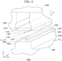
- FIG. 4 shows an example of the press apparatus (the hot press apparatus) used in the method for manufacturing a hot press-formed product according to the present embodiment.
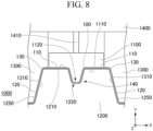
- the press apparatus 1000 shown in FIG. 4 includes a first die 1100, a second die 1200, and a third die 1300 as press dies.
- the first die 1100 and the second die 1200 are movable relative to each other in the press direction P.
- a workpiece (a blank) is sandwiched between the first die 1100 and the second die 1200.
- the third die 1300 is disposed adjacent to the first die 1100 in the direction along the X coordinate axis and is movable relative to the first die 1100 and the second die 1200.
- the third die 1300 is movable in the press direction P relative to the first die 1100 and the second die 1200. Further, a refrigerant flow path (not shown) is provided inside the second die 1200 of the press apparatus 1000.
- the press direction P in the press apparatus 1000 is a negative direction on the Y coordinate axis.
- the X coordinate axis, the Y coordinate axis, and the Z coordinate axis in FIG. 4 are orthogonal to each other.
- the first die 1100 has a press surface 1110 and a protrusion 1120 provided on the press surface 1110.
- the protrusion 1120 has a bottom surface portion 1121 and a pair of side surface portions 1122.
- the bottom surface portion 1121 is connected at end portions thereof to the side surface portions 1122 via a pair of bottom surface portion side ridge portions 1123.
- the protrusion 1120 protrudes in the negative direction on the Y coordinate axis.
- Each of the side surface portions 1122 is connected to a holding surface portion 1130 of the press surface 1110 excluding the protrusion 1120 via a side surface portion side ridge portion 1124.
- the second die 1200 has a press surface (a top surface) 1210 and a groove portion (a recessed surface portion) 1220 provided in the press surface 1210. That is, the second die 1200 has the groove portion 1220 in the top surface thereof.
- the groove portion 1220 has a bottom surface portion 1221, a pair of side surface portions 1222, a pair of bottom surface portion side ridge portions 1223, and a pair of side surface portion side ridge portions 1224.
- the bottom surface portion 1221 is connected at end portions thereof to the side surface portions 1222 via the pair of bottom surface portion side ridge portions 1223.
- the groove portion 1220 has a shape recessed in the negative direction on the Y coordinate axis.
- the third die 1300 has a press surface 1310.
- the press surface 1310 extends in a direction along the Z coordinate axis in FIG. 4 .
- the first die 1100 and the third die 1300 are disposed to face the second die 1200 in the press direction P.
- the first die 1100 is disposed facing the top surface of the second die 1200.
- the first die 1100 is defined as a die pad
- the second die 1200 is defined as a punch
- the third die 1300 is defined as a die.
- the temperature of the workpiece 1 at the start of press forming may be 600°C to 800°C.
- a pressing force may be 0.4 to 22.0 MPa. More preferably, the pressing force may be 0.4 to 4.4 MPa. This allows the workpiece to be formed while the deformation resistance is low, and further allows the forming load of the first die 1100 to be set to the minimum load force, resulting in reduced die costs.
- two third dies 1300 are shown in an X coordinate axis direction. These two third dies 1300 may be connected to each other in the X coordinate axis direction.
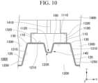
- FIG. 10 shows a state in which the workpiece is sandwiched by the dies and the third die 1300 is moved to the bottom dead point.
- the workpiece is sandwiched by the second die 1200 and the third die 1300, and the second sheet portion 120 is formed between the second die 1200 and the third die 1300, thereby completing the press forming.
- the first sheet portion 110, the second sheet portion 120, the ridge portion 130, and the recessed portion 140 are formed in the hot press-formed product 100.
- the third die 1300 includes the step portion 1320, the first die 1100 comes into contact with the third die 1300 in the press direction P at a bottom dead point of a forming process. As a result, the first die 1100 is pressed against the third die 1300, and thus it is possible to suppress necking even in a case in which the pressing force of the first die 1100 is insufficient. At this time, the support portion 1410 is deformed to be contracted in the press direction P.
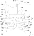
- FIG. 11 another form of the press apparatus 1000 is shown in FIG. 11 .
- the press apparatus 1000 in FIG. 11 is also a schematic end view of a cut portion of the press apparatus shown in FIG. 4 viewed in a cross section at cross section line A-A in a direction along the Z coordinate axis, similar to FIG. 5 and the like.
- the third die 1300 is provided on only one side.
- the third die 1300 has the step portion 1320.
- the first die 1100 also has a press surface 1140 on a side opposite to the third die 1300 in the X axis direction.
- the press surface 1140 is provided to be connected to the press surface 1110 of the first die 1100.
- the press surface 1140 extends in a direction along the Z coordinate axis.
- the press apparatus 1000 shown in FIG. 11 has the same configuration as the press apparatus 1000 shown in FIG. 9 , except that the third die 1300 is provided on only one side, and therefore a description thereof will be omitted here. That is, the configuration of the press apparatus 1000 according to the FIG. 9 can be applied to the press apparatus 1000 shown in FIG. 11 .
- the press apparatus 1000 in FIG. 11 has an advantage that an area for arranging a pressing mechanism of the third die 1300 on an upper side of the press apparatus 1000 can be increased, allowing for some likelihood in the press load design.
- press forming may be performed such that a ratio of an area of the recessed portion 140 to an area of the first sheet portion 110 is 30% or more when viewed in a plane in a direction perpendicular to the sheet surface of the first sheet portion 110.
- the direction perpendicular to the sheet surface of the first sheet portion 110 means a direction, on an imaginary plane that includes the shortest straight line connecting the boundary gb1 and the boundary gb2 and on which a cross-sectional line length of the recessed portion 140 is the smallest when viewed in a cross section, orthogonal to the straight line connecting the boundary gb1 and the boundary gb2.
- the cross-sectional line length of the recessed portion 140 can be measured by creating a 3D model on the basis of three-dimensional shape measurement of the hot press-formed product 100 and deriving the plane in which the cross-sectional line length is the smallest.
- the three-dimensional shape measurement described in the present embodiment can be performed using a 3D scanner such as Atos (manufactured by GOM).
- press forming may be performed such that the maximum depth dmax in a depth d of the recessed portion 140 in the press direction P is 15 mm or more.
- the depth d of the recessed portion 140 means a depth in the press direction P.
- the press direction P is a direction perpendicular to the sheet surface of the first sheet portion 110.
- the maximum depth dmax means the maximum value of the depth d of the recessed portion 140 in the entire recessed portion 140. Since the maximum depth dmax is 15 mm or more, it is possible to obtain an effect of improving the compressive axial force performance in the direction along the Z coordinate axis or the moment bending performance around the direction along the X coordinate axis shown in FIG. 1 and the like.
- the depth of the recessed portion 140 means a distance from the straight line in the direction perpendicular to the sheet surface of the first sheet portion 110 described above to the bottom portion inner surface 141a.
- the curve C corresponds to the shape of the inner surface of the recessed portion 140 in this cross section.
- the curve C has a point iP1 and a point iP2, which are one end points of the side portion 142, between the boundary gb1 or the boundary gb2 and the point pd.
- the point iP1 and the point iP2 are also the R ends of the side portion side ridge portion 144.
- the ratio of the area of the recessed portion 140 to the area of the first sheet portion 110 may be 30% or more when viewed in a plane in a direction perpendicular to the sheet surface of the first sheet portion 110.
- the area of the first sheet portion 110 is an area of a portion including the recessed portion 140 and excluding the second sheet portion 120 and the ridge portion 130 between the first sheet portion 110 and the second sheet portion 120.
- the area of the first sheet portion 110 is defined as an area of the range surrounded by the boundary between the ridge portion 130 and the first sheet portion 110 and the end portions of the first sheet portion 110 in the longitudinal direction in a plan view in a direction perpendicular to the sheet surface of the first sheet portion 110.
- the boundary between the first sheet portion 110 and the ridge portion 130 can be specified by creating a 3D model on the basis of three-dimensional shape measurement of the hot press-formed product 100 and detecting the boundary between the first sheet portion 110 and the ridge portion 130 from this 3D model.
- the area of the recessed portion 140 is defined as an area of the range on a side of the recessed portion 140 surrounded by the boundary between the side portion side ridge portion 144 and the first sheet portion 110.
- the sheet thicknesses of the first sheet portion 110 and the recessed portion 140 are measured by creating a 3D model on the basis of three-dimensional shape measurement of the hot press-formed product 100 and detecting the sheet thickness from this 3D model as described above.
- the maximum distance in the press direction from the press surface 1110 to the protrusion 1120 may be 15 mm or more.
- the press direction intersects with the press surface 1110.
- the maximum distance in the press direction from the press surface 1110 to the protrusion 1120 means the maximum distance in the press direction from the holding surface portion 1130 to the protrusion 1120.
- first die 2100 processes the second sheet portion 120 and the flange portion connected to the second sheet portion 120 while clamping them together with the third die 2300 during press forming. Since the fourth die 2400 is further provided, there is an effect of suppressing the occurrence of wrinkles in the flange portion.
- the third die 2300 is connected to a slide plate 1400.
- the first die 2100 is connected to the slide plate 1400 via a support portion 1410 (a spring or a piston).
- a recessed portion 250 shallower than a recessed portion 240 may be further provided in a first sheet portion 210.
- the hot press-formed product 100 having two second sheet portions 120 is used as an example for explanation, but the hot press-formed product according to the present disclosure may also have the second sheet portion 120 on only one side of the first sheet portion 110.
- 14B tensile test is obtained from the first sheet portion 110 or the second sheet portion 120 of the hot press-formed product 100, and the tensile strength of this sample is measured using a universal testing machine or a hydraulic servo type strength testing machine in accordance with a method conforming to JIS Z 2241, and this tensile strength is regarded as the tensile strength of the hot press-formed product 100.
- a micro tensile test piece may be used as the sample.
- the width or sheet thickness of a parallel portion is preferably 0.2 to 2.0 mm, and a test piece shape formed such that a uniform load is applied within the parallel portion of the tensile test is preferable.
- the test piece is preferably machined by wire cut electric discharge machining.
- the micro tensile test piece for example, the test piece in the Journal of the Japan Welding Society, Vol. 75 (2006), No. 6, pp. 461-465 (https://www.jstage.jst.go.jp/article/jjws175/6/75 6 461/_pdf/-char/ja) can be used.
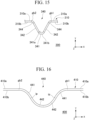
- the recessed portion may have a V-shaped cross-sectional shape including a curve in part, as shown in FIG. 15 , or a cross-sectional shape including a curve, as shown in FIG. 16 .
- a distance between the boundary gb1 and the boundary gb2 is defined as a width of the recessed portion 340.
- the definition of the curve corresponding to the shape of the recessed portion is the same as that in the above embodiment.
- a recessed portion 440 does not have flat side portions as illustrated in FIG. 3 , but rather includes a curve that corresponds to the shape of the inner surface of the recessed portion 440.
- the curve includes a curved portion 441 and a curved portion 442, and an intersection point of the curved portion 441 and the curved portion 442 is a point ip.
- FIGS. 17 to 23 show modification examples of the recessed portion provided in the first sheet portion.
- FIGS. 17 to 23 schematically show only the shape of the recessed portion provided in the first sheet portion.
- the press-formed product according to the above embodiment is preferably used as a hot press-formed product for a vehicle, such as a front bumper reinforcement, a rear bumper reinforcement, a side sill outer, a side sill inner, a door impact beam, a front side member, and a rear side member.
- Example 1 a three-point bending test was performed in a simulation on the hot press-formed product having three recessed portions as shown in FIG. 14 .
- the sheet thickness of a workpiece was set to 1.2 mm, and the tensile strength of the workpiece was set to a 2000 MPa class.
- the conditions for the simulation of the three-point bending test three-point bending in which the center of a member was pressed down statically was performed, and the sheet thickness of the central recessed portion of the member was set to a sheet thickness obtained by the forming simulation.
- the span of a receiving jig for the three-point bending was set to 1000 mm.
- the area ratio of the recessed portions was set to 40%, the maximum depth was set to 15 mm, and the width was set to 35 mm.
- the angle between the side portion of the recessed portions and the press direction during press forming was changed as shown in Table 1.
- the sheet thickness reduction rate at the recessed portion and the component performance were investigated. The results are shown in Table 1.
- (ta - tmin)/ta is defined as the sheet thickness reduction rate at the recessed portion.
- the sheet thickness reduction rate at the recessed portion can be calculated by dividing the sheet thickness reduced at a portion of the recessed portion at which the sheet thickness is reduced the most by the sheet thickness of the first sheet portion in the simulation.
- the yield strength of the member for evaluating the member performance was calculated from the simulation results of the three-point bending test.
- the yield strength is a value obtained by dividing a load, which an impactor pressing down in the three-point bending test receives from the test piece, by a weight, and this is used to evaluate the component performance.
- the load is a load that the impactor receives from the test piece
- the weight is a weight of the hot press-formed product.
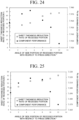
- FIG. 24 shows the results of this simulation. According to FIG. 24 , it was confirmed that the sheet thickness reduction rate can be suppressed by setting the angle of the side portion of the recessed portion to 8° or less with respect to the press direction. It was also found that, when the angle of the side portion of the recessed portion is in the range of 2° to 8° with respect to the press direction, a high component performance of 7.96 kN/kg or more, which is a target component performance, can be achieved. It was also found that, when the angle of the side portion of the recessed portion is 2° or more with respect to the press direction, the press-formed product can be easily released from the die.
- Example 2 a three-point bending test was performed in a simulation on the hot press-formed product having one recessed portion as shown in FIG. 1 .
- the sheet thickness of a workpiece was set to 2.01 mm, and the tensile strength of the workpiece was set to a 2000 MPa class.
- the conditions for the simulation of the three-point bending test three-point bending in which the center of a member was pressed down statically was performed, and the sheet thickness of the central recessed portion of the member was set to a sheet thickness obtained by the forming simulation.
- the span of a receiving jig for the three-point bending was set to 1000 mm.
- the area ratio of the recessed portions was set to 35%, the maximum depth was set to 20 mm, and the width was set to 35 mm.
- the angle between the side portion of the recessed portions and the press direction during press forming was changed as shown in Table 2, and the sheet thickness reduction rate at the recessed portion and the component performance (the yield strength) were investigated.
- the results are shown in Table 2.
- the definitions and calculation methods of the sheet thickness reduction rate at the recessed portion and the component performance are the same as those in Example 1.
- the definitions of the load and the like in Table 2 are the same as those in Table 1.
- the sheet thickness of the workpiece, the number of recessed portions, the tensile strength of the workpiece, and the pad pressure during forming (the pressing force of the first die) were changed, the three-point bending test of the test piece was performed in a simulation, and an overall evaluation was performed from the member yield strength performance and the die cost.
- the height of the second sheet portion was set to 65 mm
- the width of the first sheet portion was set to 100 mm
- the width of the recessed portion was set to 40 mm
- the depth of the recessed portion was set to 23 mm.
- the angle of the side portion of the recessed portion was set to 5° with respect to the press direction.
Landscapes
- Engineering & Computer Science (AREA)
- Mechanical Engineering (AREA)
- Physics & Mathematics (AREA)
- Thermal Sciences (AREA)
- Shaping Metal By Deep-Drawing, Or The Like (AREA)
- Mounting, Exchange, And Manufacturing Of Dies (AREA)
- Forging (AREA)
Applications Claiming Priority (2)
| Application Number | Priority Date | Filing Date | Title |
|---|---|---|---|
| JP2022085778 | 2022-05-26 | ||
| PCT/JP2023/019628 WO2023229025A1 (ja) | 2022-05-26 | 2023-05-26 | 熱間プレス装置、熱間プレス成形品の製造方法及び熱間プレス成形品 |
Publications (2)
| Publication Number | Publication Date |
|---|---|
| EP4534218A1 true EP4534218A1 (de) | 2025-04-09 |
| EP4534218A4 EP4534218A4 (de) | 2025-07-16 |
Family
ID=88919487
Family Applications (1)
| Application Number | Title | Priority Date | Filing Date |
|---|---|---|---|
| EP23811897.0A Pending EP4534218A4 (de) | 2022-05-26 | 2023-05-26 | Heisspressvorrichtung, herstellungsverfahren für heissgepressten formartikel und heissgepresster formartikel |
Country Status (8)
| Country | Link |
|---|---|
| US (1) | US20250289048A1 (de) |
| EP (1) | EP4534218A4 (de) |
| JP (1) | JP7712589B2 (de) |
| KR (1) | KR20250006115A (de) |
| CN (1) | CN119212808A (de) |
| CA (1) | CA3251035A1 (de) |
| MX (1) | MX2024013439A (de) |
| WO (1) | WO2023229025A1 (de) |
Family Cites Families (10)
| Publication number | Priority date | Publication date | Assignee | Title |
|---|---|---|---|---|
| JPS5641348Y2 (de) | 1976-08-20 | 1981-09-28 | ||
| JPS5956927A (ja) * | 1982-09-24 | 1984-04-02 | Nissan Motor Co Ltd | プレス型 |
| JP5329188B2 (ja) | 2008-11-21 | 2013-10-30 | 株式会社アステア | バンパ補強材 |
| KR101427918B1 (ko) * | 2012-10-05 | 2014-08-08 | 현대자동차 주식회사 | 핫 스탬핑 성형 장치 및 그 방법 |
| EP3088092B1 (de) * | 2015-04-30 | 2017-06-07 | Benteler Automobiltechnik GmbH | Warmumform- und presshärtewerkzeug sowie verfahren zum betreiben des warmumform- und presshärtewerkzeuges |
| JP6985989B2 (ja) * | 2018-06-26 | 2021-12-22 | 株式会社神戸製鋼所 | プレス成形品の製造方法 |
| JP7080157B2 (ja) | 2018-11-08 | 2022-06-03 | 株式会社神戸製鋼所 | プレス成形品の製造方法および製造装置 |
| CN113165299B (zh) * | 2018-11-28 | 2023-05-02 | 日本制铁株式会社 | 冲压成形品的制造方法、金属板集、冲压装置以及冲压生产线 |
| JP7335197B2 (ja) * | 2020-04-20 | 2023-08-29 | 豊田鉄工株式会社 | 長尺形状部品のプレス成形法、及び同成形法により成形した車両用ピラー部材 |
| JP2022085778A (ja) | 2020-11-27 | 2022-06-08 | キヤノン株式会社 | 定着器 |
-
2023
- 2023-05-26 CA CA3251035A patent/CA3251035A1/en active Pending
- 2023-05-26 EP EP23811897.0A patent/EP4534218A4/de active Pending
- 2023-05-26 KR KR1020247037742A patent/KR20250006115A/ko active Pending
- 2023-05-26 WO PCT/JP2023/019628 patent/WO2023229025A1/ja not_active Ceased
- 2023-05-26 US US18/859,939 patent/US20250289048A1/en active Pending
- 2023-05-26 JP JP2024523358A patent/JP7712589B2/ja active Active
- 2023-05-26 CN CN202380040763.6A patent/CN119212808A/zh active Pending
-
2024
- 2024-10-30 MX MX2024013439A patent/MX2024013439A/es unknown
Also Published As
| Publication number | Publication date |
|---|---|
| CA3251035A1 (en) | 2025-07-10 |
| CN119212808A (zh) | 2024-12-27 |
| MX2024013439A (es) | 2024-12-06 |
| EP4534218A4 (de) | 2025-07-16 |
| JPWO2023229025A1 (de) | 2023-11-30 |
| WO2023229025A1 (ja) | 2023-11-30 |
| JP7712589B2 (ja) | 2025-07-24 |
| KR20250006115A (ko) | 2025-01-10 |
| US20250289048A1 (en) | 2025-09-18 |
Similar Documents
| Publication | Publication Date | Title |
|---|---|---|
| EP2896467B1 (de) | Verfahren zur herstellung gekrümmter artikel | |
| KR101863482B1 (ko) | 프레스 성형품 및 이것을 구비한 자동차용 구조 부재, 및 그 프레스 성형품의 제조 방법 및 제조 장치 | |
| KR101863469B1 (ko) | 강판 소재, 그 제조 방법 및 제조 장치, 및 그 강판 소재를 이용한 프레스 성형품의 제조 방법 | |
| CN107530754B (zh) | 压制加工装置、压制加工方法 | |
| CN105188980A (zh) | 冲压成形部件的制造方法以及冲压成形装置 | |
| CN114260349B (zh) | 压制成形品的制造方法及成形用模具 | |
| US11534815B2 (en) | Press formed product, automobile structural member with the press formed product, and method for producing press formed product | |
| KR101579028B1 (ko) | 폐단면 구조 부품의 제조 방법 및 장치 | |
| US20230191468A1 (en) | Overlapped blank and molding method thereof | |
| US11925968B2 (en) | Method for manufacturing press-formed article, press-formed article, and press-forming apparatus | |
| EP3915694B1 (de) | Pressformverfahren und pressmaschine | |
| JP3854525B2 (ja) | プレス成形方法および成形装置 | |
| EP4534218A1 (de) | Heisspressvorrichtung, herstellungsverfahren für heissgepressten formartikel und heissgepresster formartikel | |
| US9669444B2 (en) | Method of manufacturing curvilineal closed structure parts without flange and apparatus for the same | |
| US12030100B1 (en) | Press forming method | |
| WO2024105714A1 (ja) | 構造部材及びその製造方法 | |
| JP7525817B1 (ja) | 構造部材及びその製造方法 | |
| US11833564B2 (en) | Forming apparatus and forming method using forming apparatus | |
| JP7655301B2 (ja) | プレス成形装置、及びプレス成形品の製造方法 | |
| WO2025253871A1 (ja) | プレス成形品の製造方法、金型セット及びドアインナーパネル | |
| JP7352123B1 (ja) | プレス成形品の製造方法 | |
| CN1486803A (zh) | 金属板材冲压及内缘挤压强化工艺 |
Legal Events
| Date | Code | Title | Description |
|---|---|---|---|
| STAA | Information on the status of an ep patent application or granted ep patent |
Free format text: STATUS: THE INTERNATIONAL PUBLICATION HAS BEEN MADE |
|
| PUAI | Public reference made under article 153(3) epc to a published international application that has entered the european phase |
Free format text: ORIGINAL CODE: 0009012 |
|
| STAA | Information on the status of an ep patent application or granted ep patent |
Free format text: STATUS: REQUEST FOR EXAMINATION WAS MADE |
|
| 17P | Request for examination filed |
Effective date: 20241108 |
|
| AK | Designated contracting states |
Kind code of ref document: A1 Designated state(s): AL AT BE BG CH CY CZ DE DK EE ES FI FR GB GR HR HU IE IS IT LI LT LU LV MC ME MK MT NL NO PL PT RO RS SE SI SK SM TR |
|
| A4 | Supplementary search report drawn up and despatched |
Effective date: 20250617 |
|
| RIC1 | Information provided on ipc code assigned before grant |
Ipc: B21D 22/20 20060101AFI20250611BHEP Ipc: B21D 22/26 20060101ALI20250611BHEP Ipc: B21D 24/00 20060101ALI20250611BHEP |
|
| DAV | Request for validation of the european patent (deleted) | ||
| DAX | Request for extension of the european patent (deleted) |