EP4534227A1 - Joint soudé par points, et procédé de fabrication de joint soudé par points - Google Patents
Joint soudé par points, et procédé de fabrication de joint soudé par points Download PDFInfo
- Publication number
- EP4534227A1 EP4534227A1 EP23816148.3A EP23816148A EP4534227A1 EP 4534227 A1 EP4534227 A1 EP 4534227A1 EP 23816148 A EP23816148 A EP 23816148A EP 4534227 A1 EP4534227 A1 EP 4534227A1
- Authority
- EP
- European Patent Office
- Prior art keywords
- steel sheet
- sheet
- spot
- vickers hardness
- thickness
- Prior art date
- Legal status (The legal status is an assumption and is not a legal conclusion. Google has not performed a legal analysis and makes no representation as to the accuracy of the status listed.)
- Pending
Links
Images
Classifications
-
- B—PERFORMING OPERATIONS; TRANSPORTING
- B23—MACHINE TOOLS; METAL-WORKING NOT OTHERWISE PROVIDED FOR
- B23K—SOLDERING OR UNSOLDERING; WELDING; CLADDING OR PLATING BY SOLDERING OR WELDING; CUTTING BY APPLYING HEAT LOCALLY, e.g. FLAME CUTTING; WORKING BY LASER BEAM
- B23K11/00—Resistance welding; Severing by resistance heating
- B23K11/10—Spot welding; Stitch welding
- B23K11/11—Spot welding
- B23K11/115—Spot welding by means of two electrodes placed opposite one another on both sides of the welded parts
-
- B—PERFORMING OPERATIONS; TRANSPORTING
- B23—MACHINE TOOLS; METAL-WORKING NOT OTHERWISE PROVIDED FOR
- B23K—SOLDERING OR UNSOLDERING; WELDING; CLADDING OR PLATING BY SOLDERING OR WELDING; CUTTING BY APPLYING HEAT LOCALLY, e.g. FLAME CUTTING; WORKING BY LASER BEAM
- B23K11/00—Resistance welding; Severing by resistance heating
- B23K11/16—Resistance welding; Severing by resistance heating taking account of the properties of the material to be welded
-
- B—PERFORMING OPERATIONS; TRANSPORTING
- B23—MACHINE TOOLS; METAL-WORKING NOT OTHERWISE PROVIDED FOR
- B23K—SOLDERING OR UNSOLDERING; WELDING; CLADDING OR PLATING BY SOLDERING OR WELDING; CUTTING BY APPLYING HEAT LOCALLY, e.g. FLAME CUTTING; WORKING BY LASER BEAM
- B23K2101/00—Articles made by soldering, welding or cutting
- B23K2101/006—Vehicles
-
- B—PERFORMING OPERATIONS; TRANSPORTING
- B23—MACHINE TOOLS; METAL-WORKING NOT OTHERWISE PROVIDED FOR
- B23K—SOLDERING OR UNSOLDERING; WELDING; CLADDING OR PLATING BY SOLDERING OR WELDING; CUTTING BY APPLYING HEAT LOCALLY, e.g. FLAME CUTTING; WORKING BY LASER BEAM
- B23K2101/00—Articles made by soldering, welding or cutting
- B23K2101/18—Sheet panels
-
- B—PERFORMING OPERATIONS; TRANSPORTING
- B23—MACHINE TOOLS; METAL-WORKING NOT OTHERWISE PROVIDED FOR
- B23K—SOLDERING OR UNSOLDERING; WELDING; CLADDING OR PLATING BY SOLDERING OR WELDING; CUTTING BY APPLYING HEAT LOCALLY, e.g. FLAME CUTTING; WORKING BY LASER BEAM
- B23K2103/00—Materials to be soldered, welded or cut
- B23K2103/02—Iron or ferrous alloys
- B23K2103/04—Steel or steel alloys
Definitions
- the present disclosure relates to a spot-welded joint and a method for manufacturing a spot-welded joint.
- Resistance spot welding can join steel sheets inexpensively and quickly. Therefore, resistance spot welding is used in various applications such as joining of high strength steel sheets which are materials of automobile body members.
- a decrease in joining strength and hydrogen embrittlement in a joint portion of a spot-welded joint are problems.
- One of the reasons is that the toughness of the nugget decreases as the C content in the nugget (melted portion) increases.
- the metallographic structure is optimized by applying heat treatment under various conditions. This ensures the toughness of the high strength steel sheet.
- the metallographic structure changes in the nugget and the HAZ (Heat Affected Zone) around the nugget. As a result, embrittlement of the nugget occurs. From the viewpoint of securing the joining strength of the spot-welded joint, a joining method for suppressing embrittlement of the nugget is required.
- Patent Document 1 discloses a joining structure including: a first member made of high tensile strength steel; a second member made of high tensile strength steel, the second member being overlaid on the first member; a surface soft layer formed on at least one of an overlaid surface of the first member with the second member or an overlaid surface of the second member with the first member; a melted and solidified portion formed by melting and solidifying the first member and the second member; and a heat-affected zone formed around the melted and solidified portion, in which the total thickness of the surface soft layer is 5 ⁇ m or more and 200 ⁇ m or less, a carbon amount of the melted and solidified portion is 0.35 mass% or more, and the maximum Vickers hardness of the surface soft layer in the heat-affected zone is 100 Hv or more and 500 Hv or less.
- a typical spot-welding portion is constituted of a nugget which is a melted and solidified portion, a corona bond area formed around the nugget, and a HAZ (Heat Affected Zone).
- the corona bond area is a region where melting and solidification do not occur but two steel sheets are solid-phase joined.
- the corona bond area is also referred to as a pressure-contact surface or a corona bond.
- the HAZ is a region in which melting and solidification does not occur, but the metallographic structure, the metallurgical properties, the mechanical properties, and the like are changed by the influence of welding heat.
- a spot-welded joint including a plurality of steel sheets constituted of one or more high strength steel sheets and having different tensile strengths and/or thicknesses, the spot-welded joint being capable of suppressing HAZ cracks in the vicinity of an outer peripheral side end portion of a corona bond area, and a method for manufacturing the spot-welded joint.
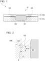
- the "steel sheet " in the spot-welded joint 1 according to the first embodiment is a concept including not only steel having a sheet shape as a whole but also steel having a sheet shape only in part, such as a member having a flange section.
- the thickness of the steel sheet 11 is also not particularly limited.
- the thickness t 1 of the first steel sheet 111 may be 1.0 to 2.6 mm
- the thickness t 2 of the second steel sheet 112 may be 0.5 to 2.3 mm.
- the thickness t 1 of the first steel sheet 111 and the thickness t 2 of the first steel sheet 111 mean thicknesses in the spot-welding portion 12.
- the thickness measured at the welded portion is regarded as t 1 or t 2 .
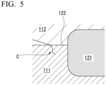
- the present inventors have found that when a sheet set constituted of a plurality of steel sheets 11 including one or more high strength steel sheets and having different tensile strengths and/or thicknesses of the steel sheets 11 is spot-welded, a crack C of a unique form occurs. Specifically, as shown in FIG. 5 , in the HAZ 123 in the vicinity of the outer peripheral side end portion 122E of the corona bond area 122, a crack C progressing in the thickness direction of the steel sheet 11 was confirmed. When the spot-welding portion 12 is viewed in a plane view, the corona bond area 122 is formed in a ring shape around the nugget 121. Therefore, the outer peripheral side end portion 122E of the corona bond area 122 can be visually recognized as an end portion on the opposite side of the nugget 121 in the cross section of the nugget 121.
- the normal spot-welding is often performed in a state where there is a slight gap between the steel sheets 11. This gap is referred to as a sheet gap.
- the steel sheet 11 is deformed by the pressing force of the electrode.
- the steel sheet 11 having low strength and/or a small sheet thickness that is, the second steel sheet 112 is greatly deformed by the pressing force of the electrode.
- the spot-welding is completed and the electrode is opened, the deformed second steel sheet 112 tries to return to the original shape, and a tensile stress is applied to the first steel sheet 111.
- the present inventors first specified a condition under which stress is likely to occur at the outer peripheral side end portion 122E of the corona bond area 122, and then prevented cracks in the vicinity of the outer peripheral side end portion 122E of the corona bond area 122.
- the present inventors have found that the conditions under which stress is likely to occur at the outer peripheral side end portion 122E of the corona bond area 122 are as follows.
- the present inventors defined the index HC of the cracks susceptibility of the HAZ 123 of the first steel sheet 111 in the vicinity of the outer peripheral side end portion 122E of the corona bond area 122 in consideration of these conditions.
- the product of "TS 2 " and "(1 - (TS 2 ⁇ t 2 3 )/(TS 1 ⁇ t 1 3 ))” included in formula 2 is the product of the index value of the deformation amount of the second steel sheet 112 at the time of spot-welding and the tensile strength of the second steel sheet 112.
- the product of "TS 2 " and “(1 - (TS 2 ⁇ t 2 3 )/(TS 1 ⁇ t 1 3 ))” is an index value of the tensile strength given to the first steel sheet 111 by the second steel sheet 112 after completion of spot-welding.
- "Ceq” included in formula 2 is an index value of the brittleness of the first steel sheet 111.
- “ ⁇ t 2 " included in formula 2, that is, t 2 0.5 is an index value of the nugget diameter.
- the index HC is 170 or more
- the HAZ 123 of the first steel sheet 111 is likely to crack in the vicinity of the outer peripheral side end portion 122E of the corona bond area 122.
- a spot-welded joint 1 having an index HC of 170 or more is required for various mechanical structural parts.
- the index HC may be 180 or more, 190 or more, or 200 or more.
- the Vickers hardness (that is, the Vickers hardness of the surface layer area of the first steel sheet 111 at the outer peripheral side end portion 122E of the corona bond area 122) of 20 ⁇ m on the first steel sheet 111 side at the outer peripheral side end portion 122E of the corona bond area 122 is the Vickers hardness measured at a portion D at a depth of 20 ⁇ m from the outer peripheral side end portion 122E of the corona bond area 122 in the first steel sheet 111 as illustrated in FIG. 2 .
- the Vickers hardness at the position of 1/4 of the sheet thickness of the first steel sheet 111 is also measured in accordance with JIS Z 2244:2009.
- the measurement surface is a cross section passing through the center of the nugget 121 and perpendicular to the surface of the steel sheet 11.
- the measurement position is a position at a depth of 1/4 of the thickness t 1 of the first steel sheet 111 from the surface of the first steel sheet 111.
- the measurement position is an outer portion the nugget 121 and the HAZ 123. Note that the HAZ softened part outside the HAZ hardened part may not be clearly visible even when etched. However, the width of the HAZ softened part is about 2 to 3 mm.
- the test force is set to 10 gf. As a result, both the measured values can be compared.
- Means for setting ⁇ Hv to 50 Hv or more is not particularly limited.
- ⁇ Hv can be set to 50 Hv or more by subjecting the first steel sheet 111 to the surface layer decarburization treatment and then performing spot-welding. Therefore, in the spot-welded joint 1 according to the first embodiment, the first steel sheet 111 may have a decarburization layer having a depth of 5 to 200 ⁇ m.
- the decarburization layer depth of the first steel sheet 111 may be 10 ⁇ m or more, 20 ⁇ m or more, or 50 ⁇ m or more.
- the decarburization layer depth of the first steel sheet 111 may be 190 ⁇ m or less, 180 ⁇ m or less, or 150 ⁇ m or less.
- the presence or absence of the decarburization layer of the first steel sheet 111 can be easily determined by locally analyzing the carbon concentrations of the surface layer and the inner portion of the first steel sheet 111 in the cross section of the spot-welding portion 12 formed perpendicularly to the surface of the steel sheet 11 and comparing the two.
- a region where the Vickers hardness is 95% or less of the Vickers hardness at the position of 1/4 of the sheet thickness of the first steel sheet 111 is regarded as a decarburization layer, and the thickness of this region is regarded as a decarburization layer depth.
- the decarburization layer depth of the first steel sheet 111 is at least 20 ⁇ m.
- ⁇ Hv can be set to 50 Hv or more.
- the decarburization layer is constituted of a microstructure containing at least one of ferrite, bainite, and martensite.
- the thickness of the layer constituted of the ferrite-based microstructure included in the decarburization layer on the surface of the first steel sheet 111 is preferably less than 5 ⁇ m.
- the microstructure observation is performed with a scanning electron microscope. Prior to the observation, a sample for microstructure observation is wet-polished with emery paper and polished with diamond abrasive grains having an average particle size of 1 ⁇ m, an observed section is finished to a mirror surface, and then the microstructure is etched with a 3% nitric acid alcohol solution.
- the observation magnification is set to 3000 x, and 10 images of a field of view of 50 ⁇ m ⁇ 50 ⁇ m are randomly captured.
- the observed visual field of view includes a region from the surface of the steel sheet to a depth of 5 ⁇ m.
- the microstructure proportion is determined by the following procedure.
- lattice-like imaginary lines arranged at intervals of 0.5 ⁇ m in length and 0.5 ⁇ m in width are arranged within a range from the surface of the steel sheet to a depth of 5 ⁇ m. Then, the area fraction of ferrite in inner portion of each lattice surrounded by the imaginary line is measured.
- Ferrite is a massive crystal grain, and does not contain an iron-based carbide having a major axis of 100 nm or more in the inner portion.
- the value obtained by dividing the area of ferrite by the area of the lattice (0.25 ⁇ m 2 ) is the area fraction of ferrite in one lattice.
- a lattice having a ferrite area fraction of 70% or more and a lattice having a ferrite area fraction of less than 70% are specified.
- the ferrite area fraction increases as it is closer to the surface of the steel sheet.
- the thickness of this layer is regarded as the thickness of a layer constituted of a ferrite-based microstructure.
- ⁇ Hv in order to set ⁇ Hv to 50 Hv or more, means other than the surface layer decarburization treatment can also be used.
- ⁇ Hv can be set to 50 Hv or more.
- ⁇ Hv can be set to 50 Hv or more by forming the first steel sheet 111 as a clad steel sheet in which mild steel and high strength steel are combined.
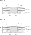
- spot-welded joint 1 in which the number of steel sheets 11 is three or more is described.
- the spot-welded joint 1 in which the number of steel sheets 11 is two has been described above.
- the spot-welded joint 1 can include three or more steel sheets 11 including one or more high strength steel sheets having a tensile strength of 1300 MPa or more or 1500 MPa or more, and a spot-welding portion 12 joining the three or more steel sheets 11.
- a high strength steel sheet is most concerned about the occurrence of cracks. Therefore, measures against cracks needs to be taken in a combination of the high strength steel sheet and the steel sheet 11 in contact with the high strength steel sheet.
- the measures against cracks are not essential.
- the steel sheet 11 third from the bottom and the steel sheet 11 second from the bottom are both mild steel sheets. It is not necessary to apply the same constitution as the spot-welded joint 1 in which the number of steel sheets 11 is two to the combination of the steel sheet 11 third from the bottom and the steel sheet 11 second from the bottom.
- spot-welded joint 1 shown in FIG. 3 there is only one "combination of high strength steel sheet and steel sheet in contact therewith".
- the spot-welded joint 1 is constituted of two high strength steel sheets and one mild steel sheet, or three high strength steel sheets, there are two "combination of high strength steel sheet and steel sheet in contact therewith".
- the same constitution as the spot-welded joint 1 in which the number of steel sheets 11 is two may be applied to at least one of the plurality of "combination of high strength steel sheet and steel sheet in contact therewith".
- the same constitution as the spot-welded joint 1 in which the number of steel sheets 11 is two is applied to at least the combination in which the index HC is the largest among the plurality of "combination of high strength steel sheet and steel sheet in contact therewith".
- the combination having the largest index HC is a combination having the highest risk of cracks. Therefore, it is more preferable to take the measures against cracks for the combination in which the index HC is the largest.
- the same constitution as the spot-welded joint 1 in which the number of steel sheets 11 is two is applied to all of the plurality of "combination of high strength steel sheet and steel sheet in contact therewith".
- the same constitution to that of the spot-welded joint 1 in which the number of steel sheets 11 is two may be applied to at least one of the combination A and the combination B.
- the combination A has a larger index HC, and is more likely to cause HAZ cracks among the combination A and the combination B. Therefore, it is preferable to apply the same constitution as the spot-welded joint 1 in which the number of steel sheets 11 is two to at least the combination A among the combination A and the combination B. More preferably, the same constitution as the spot-welded joint 1 in which the number of steel sheets 11 is two is preferably applied to both the combination A and the combination B.
- the steel sheet 11 second from the bottom is considered as the second steel sheet 112 in combination with the steel sheet 11 first from the bottom and as the first steel sheet 111 in combination with the steel sheet 11 third from the bottom.
- the spot-welded joint 1 in which the number of steel sheets 11 is three or more has the same constitution as the spot-welded joint 1 in which the number of steel sheets 11 is two.
- the preferable aspect of the spot-welded joint 1 in which the number of the steel sheets 11 is two can also be applied to the spot-welded joint 1 in which the number of the steel sheets 11 is three or more.
- the Vickers hardness from the surface of the first steel sheet 111 to a depth of 50 ⁇ m is preferably 95% or less of the Vickers hardness at the position of 1/4 of the sheet thickness of the base material portion of the first steel sheet 111.
- the decarburization layer depth of the first steel sheet 111 is preferably 50 ⁇ m or more.
- the Vickers hardness of 50 ⁇ m on the first steel sheet side at the outer peripheral side end portion of the corona bond area can be made lower by 50 Hv or more than the Vickers hardness at the position of 1/4 of the sheet thickness of the base material portion of the first steel sheet.
- the Vickers hardness from the surface of the first steel sheet 111 to a depth of 100 ⁇ m is preferably 95% or less of the Vickers hardness at the position of 1/4 of the sheet thickness of the base material portion of the first steel sheet 111.
- the decarburization layer depth of the first steel sheet 111 is preferably 100 ⁇ m or more.
- the Vickers hardness of 100 ⁇ m on the first steel sheet side at the outer peripheral side end portion of the corona bond area can be made lower by 50 Hv or more than the Vickers hardness at the position of 1/4 of the sheet thickness of the base material portion of the first steel sheet.
- the Vickers hardness of X ⁇ m (X is any number) on the first steel sheet side at the outer peripheral side end portion of the corona bond area is the Vickers hardness measured at a portion of the first steel sheet 111 at a depth of X ⁇ m from the outer peripheral side end portion 122E of the corona bond area 122.
- a method for manufacturing a spot-welded joint 1 according to a third embodiment of the present disclosure is a method for manufacturing a spot-welded joint 1 having two or more steel sheets 11.
- the method for manufacturing the spot-welded joint 1 according to the third embodiment includes: overlapping the first steel sheet 111 and the second steel sheet 112; and spot-welding the first steel sheet 111 and the second steel sheet 112, in which the tensile strength of the first steel sheet 111 is 1500 MPa or more, the tensile strength of the second steel sheet 112 is equal to or less than the tensile strength of the first steel sheet 111, the Vickers hardness from a surface of the first steel sheet 111 to a depth of 20 ⁇ m is 95% or less of the Vickers hardness at a position of 1/4 of a sheet thickness of a base material portion of the first steel sheet 111, a carbon equivalent Ceq defined by the formula 1 of the base material portion of the first steel sheet 111 is 0.22% or more, and an index HC defined by the formula 2 is 170
- An element symbol described in the formula 1 is a content in mass% of an element corresponding to the element symbol in a sheet thickness 1/4 portion of the base material portion of the first steel sheet 111
- a symbol TS 1 described in the formula 2 is the tensile strength in MPa of the first steel sheet 111
- t 1 is a sheet thickness in mm of the first steel sheet 111
- TS 2 is the tensile strength in MPa of the second steel sheet 112
- t 2 is a sheet thickness in mm of the second steel sheet 112.
- the spot-welded joint was stored at room temperature for 48 hours or more. Thereafter, the cross section of the spot-welding portion was observed, and the presence or absence of HAZ cracks in the vicinity of the outer peripheral side end portion of the corona bond area was examined.
- the nugget diameter 4 ⁇ t was adopted as a criterion. t is the thickness of the thinner one of the first steel sheet and the second steel sheet. An example in which cracks did not occur when the nugget diameter was about 4 ⁇ t was described as "Pass" in the "cracks determination" column.
- Comparative Examples 5 to 19 is a spot-welded joint having an index HC of 170 or more but ⁇ Hv of less than 50. In these Comparative Examples, HAZ cracks occurred in the vicinity of the outer peripheral side end portion of the corona bond area.
- Examples 20 to 37 is a spot-welded joint having an index HC of 170 or more and ⁇ Hv of 50 or more. In these Examples, the HAZ cracks in the vicinity of the outer peripheral side end portion of the corona bond area was suppressed.
Landscapes
- Engineering & Computer Science (AREA)
- Mechanical Engineering (AREA)
- Resistance Welding (AREA)
Applications Claiming Priority (2)
| Application Number | Priority Date | Filing Date | Title |
|---|---|---|---|
| JP2022089551 | 2022-06-01 | ||
| PCT/JP2023/020489 WO2023234391A1 (fr) | 2022-06-01 | 2023-06-01 | Joint soudé par points, et procédé de fabrication de joint soudé par points |
Publications (2)
| Publication Number | Publication Date |
|---|---|
| EP4534227A1 true EP4534227A1 (fr) | 2025-04-09 |
| EP4534227A4 EP4534227A4 (fr) | 2025-11-19 |
Family
ID=89024978
Family Applications (1)
| Application Number | Title | Priority Date | Filing Date |
|---|---|---|---|
| EP23816148.3A Pending EP4534227A4 (fr) | 2022-06-01 | 2023-06-01 | Joint soudé par points, et procédé de fabrication de joint soudé par points |
Country Status (6)
| Country | Link |
|---|---|
| EP (1) | EP4534227A4 (fr) |
| JP (1) | JP7832547B2 (fr) |
| KR (1) | KR20250002819A (fr) |
| CN (1) | CN119300941A (fr) |
| MX (1) | MX2024014594A (fr) |
| WO (1) | WO2023234391A1 (fr) |
Families Citing this family (2)
| Publication number | Priority date | Publication date | Assignee | Title |
|---|---|---|---|---|
| JP7853635B1 (ja) | 2024-09-18 | 2026-04-30 | 日本製鉄株式会社 | スポット溶接継手 |
| WO2026074859A1 (fr) * | 2024-10-01 | 2026-04-09 | Jfeスチール株式会社 | Joint soudé par points par résistance, procédé de fabrication associé et procédé d'évaluation de la résistance au pelage d'un joint soudé |
Family Cites Families (9)
| Publication number | Priority date | Publication date | Assignee | Title |
|---|---|---|---|---|
| JP2001009573A (ja) * | 1999-06-25 | 2001-01-16 | Sumitomo Metal Ind Ltd | 高張力鋼板の溶接継手およびその溶接方法 |
| JP5210552B2 (ja) * | 2007-06-19 | 2013-06-12 | 株式会社神戸製鋼所 | 高強度スポット溶接継手 |
| MX359097B (es) * | 2012-08-08 | 2018-09-14 | Nippon Steel & Sumitomo Metal Corp | Metodo para soldar partes solapadas, metodo para fabricar miembro de soldadura a solape, miembro de soldadura a solape y componente para automovil. |
| EP2987581B1 (fr) * | 2013-04-17 | 2017-11-22 | Nippon Steel & Sumitomo Metal Corporation | Procédé de soudage par points |
| JP2018193614A (ja) | 2013-07-12 | 2018-12-06 | 株式会社神戸製鋼所 | めっき性、加工性、および耐遅れ破壊特性に優れた高強度めっき鋼板、並びにその製造方法 |
| JP6451488B2 (ja) * | 2015-05-12 | 2019-01-16 | Jfeスチール株式会社 | スポット溶接部材 |
| JP6524810B2 (ja) * | 2015-06-15 | 2019-06-05 | 日本製鉄株式会社 | 耐スポット溶接部破断特性に優れた鋼板及びその製造方法 |
| JP7103923B2 (ja) | 2018-11-19 | 2022-07-20 | 株式会社神戸製鋼所 | 接合構造体及び接合構造体の製造方法 |
| JP7581812B2 (ja) | 2020-12-04 | 2024-11-13 | 富士通株式会社 | 信号処理装置及びビーム間干渉抑制方法 |
-
2023
- 2023-06-01 WO PCT/JP2023/020489 patent/WO2023234391A1/fr not_active Ceased
- 2023-06-01 EP EP23816148.3A patent/EP4534227A4/fr active Pending
- 2023-06-01 KR KR1020247041172A patent/KR20250002819A/ko active Pending
- 2023-06-01 JP JP2024524943A patent/JP7832547B2/ja active Active
- 2023-06-01 CN CN202380043577.8A patent/CN119300941A/zh active Pending
-
2024
- 2024-11-25 MX MX2024014594A patent/MX2024014594A/es unknown
Also Published As
| Publication number | Publication date |
|---|---|
| EP4534227A4 (fr) | 2025-11-19 |
| CN119300941A (zh) | 2025-01-10 |
| WO2023234391A1 (fr) | 2023-12-07 |
| KR20250002819A (ko) | 2025-01-07 |
| MX2024014594A (es) | 2025-01-09 |
| JPWO2023234391A1 (fr) | 2023-12-07 |
| JP7832547B2 (ja) | 2026-03-18 |
Similar Documents
| Publication | Publication Date | Title |
|---|---|---|
| JP7299957B2 (ja) | プレス焼入れ用の鋼およびそのような鋼材から製造されたプレス焼入れ部品 | |
| KR102836502B1 (ko) | 프로젝션 용접 조인트 및 프로젝션 용접 방법 | |
| JP6447752B2 (ja) | 抵抗溶接部を有する自動車用部材 | |
| EP3862125A1 (fr) | Structure assemblée et procédé de fabrication de structure assemblée | |
| EP4563275A1 (fr) | Élément soudé et son procédé de fabrication | |
| US20240424595A1 (en) | Resistance spot welded joint and resistance spot welding method therefor | |
| EP4265367A1 (fr) | Élément soudé présentant une excellente résistance à la fatigue de partie soudée, et son procédé de fabrication | |
| JP7832547B2 (ja) | スポット溶接継手、及びスポット溶接継手の製造方法 | |
| Dupuy | A novel electrode tip geometry to mitigate liquid metal embrittlement during resistance spot welding | |
| EP3862123A1 (fr) | Structure assemblée et procédé de fabrication d'une structure assemblée | |
| EP4592416A1 (fr) | Joint soudé par points par résistance et procédé associé de soudage par points par résistance | |
| EP3459671A1 (fr) | Structure de jonction et procédé de fabrication de structure de jonction | |
| JP7656203B2 (ja) | 抵抗スポット溶接継手及びその製造方法 | |
| JP7485242B1 (ja) | 溶接部材およびその製造方法 | |
| EP4434667A1 (fr) | Joint soudé par points par résistance et son procédé de production | |
| JP7502713B1 (ja) | スポット溶接継手、スポット溶接継手の製造方法、及び自動車部品 | |
| JP2008106324A (ja) | 重ね抵抗溶接用高強度鋼板及び重ね溶接継手 | |
| US20240352959A1 (en) | Resistance spot welded joint and resistance spot welding method therefor | |
| WO2022219968A1 (fr) | Procédé de soudage par points par résistance | |
| WO2022107580A1 (fr) | Feuille d'acier plaquée pour utilisation de soudage par points, élément de jonction, élément automobile et procédé de fabrication d'élément de jonction | |
| EP4563273A1 (fr) | Élément soudé et son procédé de fabrication | |
| EP4563274A1 (fr) | Élément soudé et son procédé de fabrication | |
| US20260091444A1 (en) | Welded member and method for producing the same | |
| WO2024181557A1 (fr) | Ébauche en couches pour estampage à chaud, corps moulé par estampage à chaud en couches et composant automobile | |
| WO2025158861A1 (fr) | Joint soudé par points et procédé de production d'un joint soudé par points |
Legal Events
| Date | Code | Title | Description |
|---|---|---|---|
| STAA | Information on the status of an ep patent application or granted ep patent |
Free format text: STATUS: THE INTERNATIONAL PUBLICATION HAS BEEN MADE |
|
| PUAI | Public reference made under article 153(3) epc to a published international application that has entered the european phase |
Free format text: ORIGINAL CODE: 0009012 |
|
| STAA | Information on the status of an ep patent application or granted ep patent |
Free format text: STATUS: REQUEST FOR EXAMINATION WAS MADE |
|
| 17P | Request for examination filed |
Effective date: 20241226 |
|
| AK | Designated contracting states |
Kind code of ref document: A1 Designated state(s): AL AT BE BG CH CY CZ DE DK EE ES FI FR GB GR HR HU IE IS IT LI LT LU LV MC ME MK MT NL NO PL PT RO RS SE SI SK SM TR |
|
| DAV | Request for validation of the european patent (deleted) | ||
| DAX | Request for extension of the european patent (deleted) | ||
| A4 | Supplementary search report drawn up and despatched |
Effective date: 20251017 |
|
| RIC1 | Information provided on ipc code assigned before grant |
Ipc: B23K 11/16 20060101AFI20251013BHEP Ipc: B23K 11/11 20060101ALI20251013BHEP Ipc: B23K 101/00 20060101ALI20251013BHEP Ipc: B23K 101/18 20060101ALI20251013BHEP Ipc: B23K 103/04 20060101ALI20251013BHEP |