EP4534264A1 - Kantenfräsaggregat und kantenanleimmaschine - Google Patents
Kantenfräsaggregat und kantenanleimmaschine Download PDFInfo
- Publication number
- EP4534264A1 EP4534264A1 EP24203846.1A EP24203846A EP4534264A1 EP 4534264 A1 EP4534264 A1 EP 4534264A1 EP 24203846 A EP24203846 A EP 24203846A EP 4534264 A1 EP4534264 A1 EP 4534264A1
- Authority
- EP
- European Patent Office
- Prior art keywords
- tool
- edge
- panel
- actuator
- along
- Prior art date
- Legal status (The legal status is an assumption and is not a legal conclusion. Google has not performed a legal analysis and makes no representation as to the accuracy of the status listed.)
- Pending
Links
Images

Classifications
-
- B—PERFORMING OPERATIONS; TRANSPORTING
- B27—WORKING OR PRESERVING WOOD OR SIMILAR MATERIAL; NAILING OR STAPLING MACHINES IN GENERAL
- B27D—WORKING VENEER OR PLYWOOD
- B27D5/00—Other working of veneer or plywood specially adapted to veneer or plywood
- B27D5/006—Trimming, chamfering or bevelling edgings, e.g. lists
Definitions
- This invention relates to an edge milling unit for machining a panel, in particular, a panel made of wood or comparable materials, such as, for example, wood by-products, metal, plastic and composites.
- This invention also relates to an edge banding machine.
- an edge milling unit is a machining unit, used typically in an edge banding machines, to machine one or more corners of an edge of a panel to be machined.
- Edge banding machines also called edging machines, or simply edge banders
- rough panel is meant a panel, made typically of particleboard material, covered by two sheets, one above and one below, of ennobling material, which, after being cut to size by panel sawing or nesting processes, have one or more edges, called rough edges, where the inner core of particleboard material is visible.
- a strip or band is glued to the rough edge of the panel to cover it.
- Each single panel may run through an edge banding station one or more times or it may run through several edge banding stations located one after another in order to cover all the rough edges of a single panel.
- the band is applied so it projects outwards, since it is larger in area than the rough edge it is intended to cover so that it is sure to cover the rough edge entirely.
- finishing stations or machining units
- finishing stations may, for example, comprise two or more substations (or sub-units), each responsible for carrying out a specific machining process on the edge band.
- edge band Described below purely by way of example is a typical sequence of machining processes performed on the edge band to make the band the same size as the rough edge of the panel and, if necessary, give its profile the desired shape (for example, rounded, sharp-cornered, bevelled) so as to obtain a panel that is aesthetically pleasing also round the edges.
- the panel advances through the edge banding machine along a feed direction which is horizontal, that is, parallel to the supporting surface of the edge banding machine, which typically defines the longitudinal axis of the edge banding machine itself.
- a first machining unit comprising at least one tool which performs an operation known as end cropping, whereby the edge band is cropped to create sharp corners at its front and back ends so one of its dimensions is the same size as the panel edge, in particular so it is the same length.
- the panel meets a second machining unit, comprising another tool which is adapted to perform an operation known as trimming, in which the excess parts along the top and bottom of the edge band are removed, so that another of its dimensions is the same size as the panel edge, in particular so it is the same height.
- a second machining unit comprising another tool which is adapted to perform an operation known as trimming, in which the excess parts along the top and bottom of the edge band are removed, so that another of its dimensions is the same size as the panel edge, in particular so it is the same height.
- edge band applied to the rough edge of the panel
- the corner of the edge may be machined in several different ways.
- a typical machining process is a simple process with a flat-faced tool, in particular, a tool whose face is inclined by 10°.
- Thicker edge bands are typically machined with contoured tools to obtain what is known as a radiused edge. Contoured tools may have different curvature radiuses so as to make differently radiused edges, for example, as a function of the thickness of the edge band applied.
- Edge bands may also be made of solid wood (in which case they are called solid wood strips), which are typically machined with flat-faced tools specific for solid wood.
- edge banding machines where the operator changes the tool and adjusts the machining unit every time what is known as a changeover takes place, i.e. every time the size of the panel, the type of edge band applied to it and/or the desired edge surface finish changes. It is evident, however, that these operations carried out manually by the operator make the edge banding machine extremely inefficient.
- edge banding machines provided with a series of machining units which perform the same machining process (we might also speak of a single machining unit comprising two or more sub-units) but which are equipped with different tools so that the result of the machining process is different.
- These machining stations are activated alternately according to the type of panel, the type of edge band and the desired surface finish. In this case, intervention by an operator to change the tools or adjust the machining units at each changeover is not necessary.
- these edge banding machines are particularly expensive and complex.
- their size, in particular their length is a function of the number of machining units or sub-units they are equipped with. Therefore, these edge banding machines are particularly large, hence expensive in terms of occupied space in a production facility.
- This invention has for an aim to provide an edge milling unit and a machine to overcome the above mentioned disadvantages of the prior art.
- the aim of this invention is to provide an edge milling unit and an edge banding machine which allow different machining processes to be performed on the panel flexibly and fully automatically without an operator having to intervene to change the tool or make any adjustments.
- Another aim of this disclosure is to provide an edge milling unit and an edge banding machine which are economical and easy to make.
- the edge milling unit may be configured for machining a panel in an edge banding machine comprising, for example, a support plane for supporting the panel, and a movement system for moving the panel along a feed direction parallel to the support plane.
- the edge milling unit may comprise, for example, a first support, connectable to the edge banding machine; a tool, connected to the first support so as to be movable along a configuration direction which is inclined with respect to the support plane and which lies in a configuration plane perpendicular to the feed direction.
- the tool may have three different cutting profiles. More specifically, the tool may have at least three cutting profiles. Furthermore, the cutting profiles may be different from each other.
- the edge milling unit may also comprise a first actuator, connected to the tool and configured to position the tool, for example, at least at three tool working positions along the configuration direction. At each tool working position, a respective cutting profile of the at least three cutting profiles may be configured to carry out a different machining process on the panel.
- the first support may comprise a fixed stop
- the tool is solidly connected to a movable stop
- the first actuator may be configured to move the movable stop relative to the fixed stop along the configuration direction. That way, the tool may be positioned along the configuration direction at the at least three tool working positions.
- the first actuator may be connected to the movable stop by a movable stop adjuster.
- the movable stop adjuster may, for example, be configured to adjust the distance between the first actuator and the movable stop.
- the piston of the adjustable stop 531 may be embodied by a screw so as to be able to adjust its extent, or length. That way, it is very easy to adjust, or vary, the travel length of the movable stop 512 relative to the fixed stop 511, limited by the adjustable stop 531. In effect, simply screwing or unscrewing the screw which embodies the adjustable stop 531 will vary the travel length of the movable stop 512.
- the first actuator 52 and the limiter 53 may be viewed as two pneumatic cylinders in series, where the limiter 53 may oppose or, rather, limit the movement produced by the first actuator 52. Therefore, it is possible, for example, to combine the movement of the movable stop 512 with the movement of the adjustable stop 513 so as to position the tool 2 at one or more working positions along the configuration direction L.
- the pneumatic cylinder which may embody the limiter 53 has to overcome the thrust of the pneumatic cylinder which may embody the first actuator 52. Since both are connected to the same compressed air system, however, for this to be possible, the cylinder 530 of the limiter actuator 53 may have a larger bore than the cylinder of the first actuator 52.
- the tool 2 may be positioned at three working positions by moving the chuck 6 relative to the first support 5 along the configuration direction L via the first actuator 52.
- the limiter 53 may cooperate with the first actuator 52 to position the tool 2 at at least one additional working position, limiting the travel length of the movable stop 512 relative to the fixed stop 511.
- the second actuator 42 may cooperate with the first actuator 52 to position the tool 2 at at least one additional working position, moving the first support 5 relative to the second support 4 along the transverse axis Y, which has a component along the configuration direction L, via the second actuator 42.
- the tool 2 may be positioned at multiple working positions along the configuration direction L.
- Figure 1c shows an example of the tool 2 which the edge milling unit 1 can be equipped with.
- the tool 2 may comprise, for example, one or more cutting profiles 21, 22, 23, 24.
- the tool 6 may comprise at least three cutting profiles 21, 22, 23, 24, i.e. three, four, five, six or more cutting profiles.
- edge milling unit 1 comprising a tool 2 having four cutting profiles 21, 22, 23, 24. It should be borne in mind, however, that the edge milling unit 1 of this invention could comprise a tool 2 having at least three cutting profiles 21, 22, 23, 24, while remaining within the scope of protection defined by the appended claims. Each cutting profile 21, 22, 23, 24 of the tool 2 may, for example, be different from the others, so that the edge milling unit 1 can perform different machining processes on the panel P.
- the tool 2 may have a first cutting profile 21 which is suitable, for example, for machining the edge of the panel P in the case where a thin edge band has been used.
- the first cutting profile 21 may substantially be a straight profile which is parallel to the transverse axis Y when the axis of the tool is positioned along the configuration direction L. That way, a sharp corner is made along the edge of the panel P.
- the tool 2 may have a second cutting profile 22 which is suitable, for example, for machining the edge of the panel P in the case where a thick edge band, made of plastic material, for example, has been used.
- the second cutting profile 22 may have a radius, in particular a minor radius, configured to radius the edge band, thereby making a transitional portion between the edge band and the panel P to create a rounded effect.
- the second cutting profile 22 may be configured to round the edge of the panel P when the axis of the tool is positioned along the configuration direction L.
- the tool 2 may have a third cutting profile 23 which is suitable, for example, for machining the edge of the panel P in the case where a thick edge band, made of plastic material, for example, has been used.
- the third cutting profile 23 may have a radius, in particular a major radius, larger than the minor radius of the second cutting profile 22, configured to radius the edge band, thereby making a transitional portion between the edge band and the panel P to create a rounded effect.
- the third cutting profile 23 may be configured to round the edge of the panel P when the axis of the tool is positioned along the configuration direction L.
- the tool 2 may have a fourth cutting profile 24 which is suitable, for example, for machining the edge of the panel P in the case where an edge band, made of solid wood, for example, has been used.
- the fourth cutting profile 24 may substantially be a straight profile which is parallel to the transverse axis Y when the axis of the tool is positioned along the configuration direction L. That way, a sharp corner is made along the edge of the panel P.
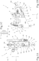
- the edge milling unit 1 may comprise a bottom copier adjuster 321, configured to adjust the position of the bottom copier 32 relative to the first support 5, hence relative to the tool 2. Furthermore, the edge milling unit 1 may comprise a lateral copier adjuster 322, configured to adjust the position of the lateral copier 31 relative to the first support 5, hence relative to the tool 2. Described below is an example of how the edge milling unit 1 according to the invention operates.
- the lateral copier 31 and the bottom copier 32 are in abutment against the panel P to be machined, thus referencing the position of the first support 5, hence of the tool 2, relative to the panel P.
- the second actuator 42 does not act on the second support 4, as is evident from the example of Figure 1b .
- the limiter 53 is in the inactive configuration and therefore, the adjustable stop 531 does not interfere with, and does not limit the travel length of, the movable stop 512, as is evident from the example of Figure 1a .
- the first actuator 52 is at the fully extended operating position, so the movable stop 512 is at a position distal to the fixed stop 511.
- the tool 2 is thus at a first working position along the configuration direction L. At this first working position of the tool 2, the first tool profile 21 is in contact with the panel P to be machined, to make a sharp corner.
- This configuration of the edge milling unit 1 may be particularly suitable in the case of thin edge bands.
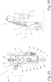
- the lateral copier 31 and the bottom copier 32 are in abutment against the panel P to be machined, thus referencing the position of the first support 5, hence of the tool 2, relative to the panel P.
- the second actuator 42 acts on the second support 4, as is evident from the example of Figure 2b , thus producing a movement between the first support 5 and the second support 4, hence moving the tool 2 along the configuration direction L.
- the limiter 53 is in the inactive configuration and therefore, the adjustable stop 531 does not interfere with, and does not limit the travel length of, the movable stop 512, as is evident from the example of Figure 2a .
- the first actuator 52 is at the fully retracted operating position, so the movable stop 512 is at a position proximal to the fixed stop 511.
- the tool 2 is thus at a second working position along the configuration direction L.
- the fourth tool profile 24 is in contact with the panel P to be machined, to make a sharp corner.
- This configuration of the edge milling unit 1 may be particularly suitable in the case of edge bands made of solid wood.
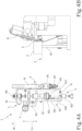
- the lateral copier 31 and the bottom copier 32 are in abutment against the panel P to be machined, thus referencing the position of the first support 5, hence of the tool 2, relative to the panel P.
- the second actuator 42 does not act on the second support 4, as is evident from the example of Figure 3b .
- the limiter 53 is in the inactive configuration and therefore, the adjustable stop 531 does not interfere with, and does not limit the travel length of, the movable stop 512, as is evident from the example of Figure 3a .
- the first actuator 52 is at the intermediate operating position, so the movable stop 512 is at an intermediate position relative to the fixed stop 511.
- the tool 2 is thus at a third working position along the configuration direction L.
- the third tool profile 23 is in contact with the panel P to be machined, to make a radiused, i.e. rounded, corner, with a maximum radius.
- This configuration of the edge milling unit 1 may be particularly suitable in the case of thick edge bands, in particular made of plastic material.
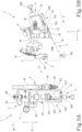
- the lateral copier 31 and the bottom copier 32 are in abutment against the panel P to be machined, thus referencing the position of the first support 5, hence of the tool 2, relative to the panel P.
- the second actuator 42 does not act on the second support 4, as is evident from the example of Figure 4b .
- the limiter 53 is in the active configuration and therefore, the adjustable stop 531 interferes with, and limits the travel length of, the movable stop 512, as is evident from the example of Figure 4a .
- the first actuator 52 is driven to move to the fully extended operating position but the adjustable stop 531 limits the chord of the movable stop 512, which moves to an additional intermediate position relative to the fixed stop 511.
- the tool 2 is thus at a fourth working position along the configuration direction L.
- the second tool profile 22 is in contact with the panel P to be machined, to make a radiused, i.e. rounded, corner, with a minimum radius.
- This configuration of the edge milling unit 1 may be particularly suitable in the case of thick edge bands, in particular made of plastic material.
- the lateral copier 31 and the bottom copier 32 are in abutment against the panel P to be machined, thus referencing the position of the first support 5, hence of the tool 2, relative to the panel P.
- the second actuator 42 acts on the second support 4, as is evident from the example of Figure 5b , thus producing a movement between the first support 5 and the second support 4, hence moving the tool 2 along the configuration direction L.
- the limiter 53 is in the inactive configuration and therefore, the adjustable stop 531 does not interfere with, and does not limit the travel length of, the movable stop 512, as is evident from the example of Figure 5a .
- the first actuator 52 is at the fully extended operating position, so the movable stop 512 is at a position distal to the fixed stop 511.
- the tool 2 is thus at a non-working position along the configuration direction L. At this non-working position, the tool 2 is excluded from machining the panel P.
- the edge milling unit 1 may be equipped with a tool 2 having one or more cutting profiles 21, 22, 23, 24, in particular, at least three cutting profiles 21, 22, 23, 24, so as to be able to perform one or more machining processes on the edge of the panel P.
- Each working position of the tool 2 can be associated with a respective cutting profile 21, 22, 23, 24. That way, moving the tool 2 along the configuration direction L makes it possible to perform different machining processes on the panel without necessitating the intervention of an operator to change the tool or adjust the edge milling unit 1.
- the first actuator 52, the second actuator 42 and/or the limiter actuator 530 may advantageously be embodied, for example, as pneumatic cylinders, or discrete actuators, which usually cost less and are easier to control and drive.
- the multiple working positions along the configuration direction L are discrete positions, i.e., the motion along the configuration direction L of the tool 2 is not continuous motion but is performed in discrete steps, passing through predetermined, known working positions.
- the edge milling unit may comprise one or more adjustments of the position of the tool 2 along the configuration direction L: the stop element 44, the movable stop adjuster 513 and/or the standard stop. That way, while comprising discrete actuators such as pneumatic cylinders, for example, it is possible to position the tool 2 precisely and accurately.
Landscapes
- Life Sciences & Earth Sciences (AREA)
- Engineering & Computer Science (AREA)
- Mechanical Engineering (AREA)
- Wood Science & Technology (AREA)
- Forests & Forestry (AREA)
- Milling, Drilling, And Turning Of Wood (AREA)
Applications Claiming Priority (1)
| Application Number | Priority Date | Filing Date | Title |
|---|---|---|---|
| IT202300020337 | 2023-10-02 |
Publications (1)
| Publication Number | Publication Date |
|---|---|
| EP4534264A1 true EP4534264A1 (de) | 2025-04-09 |
Family
ID=89158533
Family Applications (1)
| Application Number | Title | Priority Date | Filing Date |
|---|---|---|---|
| EP24203846.1A Pending EP4534264A1 (de) | 2023-10-02 | 2024-10-01 | Kantenfräsaggregat und kantenanleimmaschine |
Country Status (1)
| Country | Link |
|---|---|
| EP (1) | EP4534264A1 (de) |
Citations (5)
| Publication number | Priority date | Publication date | Assignee | Title |
|---|---|---|---|---|
| DE3732810C1 (en) * | 1987-09-29 | 1989-04-13 | Hornberger Maschbau Gmbh | Device for working the edges of continuously moving plate-like workpieces |
| EP1782931A1 (de) * | 2005-11-07 | 2007-05-09 | Brandt Kantentechnik GmbH | Kantenfräsmaschine |
| DE102009015175A1 (de) * | 2009-03-20 | 2010-09-23 | Konrad Scholz | Verfahren und Vorrichtung zur Bearbeitung von überstehenden Kantenmaterialien an Platten |
| EP2514556A1 (de) * | 2011-04-21 | 2012-10-24 | BIESSE S.p.A. | Betriebskopf zur Bearbeitung von Holzteilen oder Ähnlichem |
| DE102013010359A1 (de) * | 2012-06-22 | 2013-12-24 | Biesse S.P.A. | Fräsgruppe zur Bearbeitung von Platten aus Holz oder ähnlichem |
-
2024
- 2024-10-01 EP EP24203846.1A patent/EP4534264A1/de active Pending
Patent Citations (5)
| Publication number | Priority date | Publication date | Assignee | Title |
|---|---|---|---|---|
| DE3732810C1 (en) * | 1987-09-29 | 1989-04-13 | Hornberger Maschbau Gmbh | Device for working the edges of continuously moving plate-like workpieces |
| EP1782931A1 (de) * | 2005-11-07 | 2007-05-09 | Brandt Kantentechnik GmbH | Kantenfräsmaschine |
| DE102009015175A1 (de) * | 2009-03-20 | 2010-09-23 | Konrad Scholz | Verfahren und Vorrichtung zur Bearbeitung von überstehenden Kantenmaterialien an Platten |
| EP2514556A1 (de) * | 2011-04-21 | 2012-10-24 | BIESSE S.p.A. | Betriebskopf zur Bearbeitung von Holzteilen oder Ähnlichem |
| DE102013010359A1 (de) * | 2012-06-22 | 2013-12-24 | Biesse S.P.A. | Fräsgruppe zur Bearbeitung von Platten aus Holz oder ähnlichem |
Similar Documents
| Publication | Publication Date | Title |
|---|---|---|
| US11325176B2 (en) | Multiple stroke slotting of planar workpieces | |
| EP2745958A2 (de) | Werkzeugmaschine mit Drehwerkzeug und Fräswerkzeug | |
| CN213224481U (zh) | 一种数控v型双刨槽机 | |
| CN102350524A (zh) | 薄壁结构件开口端头内型面铣削加工方法 | |
| CN211489833U (zh) | 一种适应性强的剪板机 | |
| US11376647B2 (en) | Tools, machines, and methods for machining planar workpieces | |
| CN211662241U (zh) | 一种可减少毛刺的自动加工竹木制品铣床 | |
| EP0997245B1 (de) | Paneelkantenbearbeitungseinheit | |
| US11471924B2 (en) | Tools, machines, and methods for processing planar workpieces | |
| KR20200086855A (ko) | 측면 가공장치의 보조구동수단을 갖는 엣지벤딩기 | |
| CN215035226U (zh) | 一种集激光切割与铣削加工的组合式加工装置 | |
| EP1853737B1 (de) | Arbeitstisch für eine automatische maschine zum zuschneiden von leder und dergleichen | |
| CN212330569U (zh) | 一种分切v槽磨边多功能机 | |
| CN112809386A (zh) | 一种集激光切割与铣削加工的组合式加工装置 | |
| CN102626936A (zh) | 数控木工机床及利用其精细加工木制品的方法 | |
| CN216941098U (zh) | 数控开料机 | |
| CN105252273A (zh) | 一种刨槽和剪板一体化的数控刨剪机 | |
| EP4516470A1 (de) | Bearbeitungseinheit | |
| CN213531821U (zh) | 一种新型复合加工中心用移动装置 | |
| CN204818225U (zh) | 插床进让刀机构 | |
| CN110977005B (zh) | 切割装置、切割机及切割方法 | |
| CN114309352A (zh) | 一种细丝截取整形装置 | |
| CN117136113A (zh) | 用于准备分割至少两个工件的准备方法、计算机程序产品、计算机可读的存储介质,以及板材分割设备 | |
| CN217913154U (zh) | 一种用于切割装饰件间隙的切缝定位装置 | |
| CN210414899U (zh) | 一种斜边齐头齐尾总装配机 |
Legal Events
| Date | Code | Title | Description |
|---|---|---|---|
| PUAI | Public reference made under article 153(3) epc to a published international application that has entered the european phase |
Free format text: ORIGINAL CODE: 0009012 |
|
| STAA | Information on the status of an ep patent application or granted ep patent |
Free format text: STATUS: THE APPLICATION HAS BEEN PUBLISHED |
|
| AK | Designated contracting states |
Kind code of ref document: A1 Designated state(s): AL AT BE BG CH CY CZ DE DK EE ES FI FR GB GR HR HU IE IS IT LI LT LU LV MC ME MK MT NL NO PL PT RO RS SE SI SK SM TR |
|
| STAA | Information on the status of an ep patent application or granted ep patent |
Free format text: STATUS: REQUEST FOR EXAMINATION WAS MADE |
|
| 17P | Request for examination filed |
Effective date: 20251008 |