EP4534317A1 - Transmission à prise de force - Google Patents
Transmission à prise de force Download PDFInfo
- Publication number
- EP4534317A1 EP4534317A1 EP24202144.2A EP24202144A EP4534317A1 EP 4534317 A1 EP4534317 A1 EP 4534317A1 EP 24202144 A EP24202144 A EP 24202144A EP 4534317 A1 EP4534317 A1 EP 4534317A1
- Authority
- EP
- European Patent Office
- Prior art keywords
- input
- input shaft
- synchronizer
- axial position
- transmission
- Prior art date
- Legal status (The legal status is an assumption and is not a legal conclusion. Google has not performed a legal analysis and makes no representation as to the accuracy of the status listed.)
- Pending
Links
Images


Classifications
-
- F—MECHANICAL ENGINEERING; LIGHTING; HEATING; WEAPONS; BLASTING
- F16—ENGINEERING ELEMENTS AND UNITS; GENERAL MEASURES FOR PRODUCING AND MAINTAINING EFFECTIVE FUNCTIONING OF MACHINES OR INSTALLATIONS; THERMAL INSULATION IN GENERAL
- F16H—GEARING
- F16H3/00—Toothed gearings for conveying rotary motion with variable gear ratio or for reversing rotary motion
- F16H3/02—Toothed gearings for conveying rotary motion with variable gear ratio or for reversing rotary motion without gears having orbital motion
- F16H3/08—Toothed gearings for conveying rotary motion with variable gear ratio or for reversing rotary motion without gears having orbital motion exclusively or essentially with continuously meshing gears, that can be disengaged from their shafts
- F16H3/087—Toothed gearings for conveying rotary motion with variable gear ratio or for reversing rotary motion without gears having orbital motion exclusively or essentially with continuously meshing gears, that can be disengaged from their shafts characterised by the disposition of the gears
- F16H3/089—Toothed gearings for conveying rotary motion with variable gear ratio or for reversing rotary motion without gears having orbital motion exclusively or essentially with continuously meshing gears, that can be disengaged from their shafts characterised by the disposition of the gears all of the meshing gears being supported by a pair of parallel shafts, one being the input shaft and the other the output shaft, there being no countershaft involved
-
- B—PERFORMING OPERATIONS; TRANSPORTING
- B60—VEHICLES IN GENERAL
- B60K—ARRANGEMENT OR MOUNTING OF PROPULSION UNITS OR OF TRANSMISSIONS IN VEHICLES; ARRANGEMENT OR MOUNTING OF PLURAL DIVERSE PRIME-MOVERS IN VEHICLES; AUXILIARY DRIVES FOR VEHICLES; INSTRUMENTATION OR DASHBOARDS FOR VEHICLES; ARRANGEMENTS IN CONNECTION WITH COOLING, AIR INTAKE, GAS EXHAUST OR FUEL SUPPLY OF PROPULSION UNITS IN VEHICLES
- B60K17/00—Arrangement or mounting of transmissions in vehicles
- B60K17/28—Arrangement or mounting of transmissions in vehicles characterised by arrangement, location, or type of power take-off
-
- F—MECHANICAL ENGINEERING; LIGHTING; HEATING; WEAPONS; BLASTING
- F16—ENGINEERING ELEMENTS AND UNITS; GENERAL MEASURES FOR PRODUCING AND MAINTAINING EFFECTIVE FUNCTIONING OF MACHINES OR INSTALLATIONS; THERMAL INSULATION IN GENERAL
- F16H—GEARING
- F16H63/00—Control outputs from the control unit to change-speed- or reversing-gearings for conveying rotary motion or to other devices than the final output mechanism
- F16H63/02—Final output mechanisms therefor; Actuating means for the final output mechanisms
- F16H63/30—Constructional features of the final output mechanisms
- F16H63/3013—Constructional features of the final output mechanisms the final output mechanism being characterised by linkages converting movement, e.g. into opposite direction by a pivoting lever linking two shift rods
-
- F—MECHANICAL ENGINEERING; LIGHTING; HEATING; WEAPONS; BLASTING
- F16—ENGINEERING ELEMENTS AND UNITS; GENERAL MEASURES FOR PRODUCING AND MAINTAINING EFFECTIVE FUNCTIONING OF MACHINES OR INSTALLATIONS; THERMAL INSULATION IN GENERAL
- F16H—GEARING
- F16H2200/00—Transmissions for multiple ratios
- F16H2200/003—Transmissions for multiple ratios characterised by the number of forward speeds
- F16H2200/0034—Transmissions for multiple ratios characterised by the number of forward speeds the gear ratios comprising two forward speeds
Definitions
- the present invention relates to a power take-off transmission, in particular a power take-off transmission for industrial and/or argricultural vehicles.
- US patent application US 2002/043121 A1 discloses a power take off drive train for an agricultural tractor, comprising an input shaft and an output shaft, where the shafts are rotatably mounted in a transmission casing.
- the input shaft mounts first and second input gear wheels and a selector, wherein the gear wheels are free to rotate on the input shaft and wherein the selector is mounted on the input shaft for rotation therewith, and to slide axially along the input shaft to engage with one of the first and second gear wheels transmitting torque thereto.
- the output shaft mounts first and second output gear wheels fixed for rotation therewith, and wherein the first and second output gear wheels being in driving engagement with the first and second input gear wheels respectively.
- German patent application DE 10 2021 209 053 A1 discloses an actuating device for a transmission element, in particular a sliding sleeve of a transmission device of a motor vehicle, comprising an actuator which is designed to move an actuating element, in particular a shift fork of the actuating device to actuate the transmission element.
- An output shaft of the actuating device is coupled to an eccentric shaft being mounted eccentrically in relation to the output shaft of the actuator, with a shaft section of the eccentric shaft engaging in a recess in the actuating element.
- the present invention seeks to provide an improved Power Take-Off, PTO, transmission that provides accurate and reliable operation, lower friction losses and higher efficiencies as well as reduced mechanical complexity.
- a PTO transmission as mentioned above is provided, comprising an input shaft rotatable around an input axis and an output shaft rotatable around an output axis, wherein the input shaft and output shaft are journalled for rotation in a casing of the PTO transmission.
- An input gear train is coaxially arranged on the input shaft, and an output gear train is driven by the input gear train and drives the output shaft when the PTO transmission is in operation.
- a synchronizer member is arranged on the input shaft and is moveable there along for connecting and disconnecting the input gear train to and from the input shaft.
- the PTO transmission is further provided with an electric actuator for moving the synchronizer member, and further comprises a clutch member for connecting and disconnecting the output gear train to and from the output shaft.
- a link arrangement mechanically connects the synchronizer member to the electric actuator, wherein the link arrangement is configured to move the synchronizer member along the input shaft in response to actuation of the electric actuator.
- the synchronizer member allows for a smooth and seamless connection of the input shaft to the input gear train, wherein the input gear train and output gear train allow for one or more gear ratios, selectable by the synchronizer member, between the input shaft and output shaft.
- the synchronizer member allows for the input gear train, the output gear train, the clutch member and the output shaft to remain stationary whilst the input shaft is being driven, thereby lowering friction losses of the PTO transmission significantly.
- the electric actuator for moving the synchronizer member also provides particular advantages over e.g. conventional hydraulic actuators.
- the electric actuator allows for programmable actuation for moving the link arrangement and hence the synchronizer member.
- the electric actuator may provide improved monitoring and/or control of actuation forces and/or actuator positions.
- the electric actuator may allow for automated positioning calibration of the synchronizer member along the input shaft, thereby ensuring seamless and smooth connection between the input shaft and the input gear train.
- the electric actuator eliminates the need for complex hydraulic actuation and hydraulic pressure and flow control.
- a power take-off, PTO, transmission 1 for a vehicle wherein the PTO transmission 1 comprises an input shaft 2 which is rotatable around an input axis Li and an output shaft 3 which is rotatable around an output axis Lo.
- the input shaft 2 and output shaft 3 are journalled for rotation in a casing 4 of the PTO transmission 1.
- the input shaft 2 may be connected to an external power source such as an engine of a vehicle, and the output shaft 3 may be connected to an implement, wherein the output shaft 3 is driven by the input shaft 2 via an internal transmission arrangement of the PTO transmission 1.
- the PTO transmission 1 comprises an input gear train 5 coaxially arranged on the input shaft 2, and further comprises an output gear train 6 driven by the input gear train 5 and driving the output shaft 3 when the PTO transmission 1 is in operation.
- a synchronizer member 7 is arranged on, e.g. coaxially arranged on, the input shaft 2 and is moveable or operable there along for connecting and disconnecting the input gear train 5 to and from the input shaft 2.
- the synchronizer member 7 operates as a "synchronizer” or “synchromesh", which is well-known to a skilled person in the field of geared transmissions.
- the synchronizer member 7 acts and operates as a movable ring shaped hub device which is configured to seamlessly and smoothly equalise a rotational speed of the input gear train 5 to a rotational speed of the input shaft 2 by utilizing friction as the synchronizer member 7 moves along the input shaft 2 in axial direction.
- the synchronizer member 7 operates differently than a regular clutch, such as a multi-plate clutch, by which clutch plates are brought into friction engagement and wherein this friction engagement is solely responsible for releasably connecting two shafts, for example.
- a regular clutch such as a multi-plate clutch
- this friction engagement is solely responsible for releasably connecting two shafts, for example.
- the aforementioned rigid connection provided by the synchronizer member 7 is equivalent to the rigid connection provided by a dog clutch as widely known in the prior art, wherein shafts are connected by interlocking teeth or dogs instead of relying on friction only.
- Such interlocking of teeth or dogs is referred to as a rigid connection as no relative rotation or slippage between the input shaft 2 and input gear train 5 can occur once the interlocking of teeth or dogs is established.
- the synchronizer member 7 as utilized by the present invention operates according to known principles of a synchronizer or synchromesh by allowing interlocking of teeth or dogs in smooth manner by first matching the rotational speeds of the input shaft 2 and the input gear train 5 before interlocking of the input shaft 2 and the input gear train 5 takes place.
- the synchronizer member 7 is able to achieve the rigid connection even when the input shaft 2 and the input gear train 5 rotate relatively with respect to each other, so it is not necessary that the input shaft 2 and the input gear train 5 must be held stationary to establish the rigid connection.
- Rotational speeds between the input shaft 2 and the input gear train 5 are matched by friction as the synchronizer member 7 is moved along the input shaft 2, i.e. along the input axis Li. More precisely, as the synchronizer member 7 is moved, friction engagement between the input shaft 2 and the input gear train 5 is established forcing the input gear train 5 to match its rotational speed with the rotational speed of the input shaft 2. Once rotational speeds are matched, further movement of the synchronizer member 7 causes a dog clutch connection to be established, i.e. a rigid connection of interlocking teeth of dogs. It is important to note that the aforementioned friction engagement merely serves to match rotational speeds of the input shaft 2 and the input gear train 5 and does not play a role in maintaining the rigid connection between the input shaft 2 and the input gear train 5.
- Arranging the synchronizer member 7 on the input shaft 2 is particularly advantageous as the synchronizer member 7 imposes much less friction than a regular clutch, e.g. plate clutch, when the input shaft 2 is driven whilst the input gear train 5 is disconnected therefrom. Consequently, the PTO transmission 1 can be driven economically in an idle state in which the output shaft 3 need not be driven whilst the input shaft 2 is driven. Further details and exemplary embodiments of the synchronizer member 7 will be explained later.
- the PTO transmission 1 comprises an electric actuator 8. Connecting and disconnecting the output gear train 6 to and from the output shaft 3 is achieved by a clutch member 9. In an engaged state of the clutch member 9, the output gear train 6 is connected to the output shaft 3. In a disengaged state of the clutch member 9, the output gear train 6 is disconnected from the output shaft 3 and as such the output shaft 3 can be held stationary whilst the output gear train 6 may still be driven.
- the clutch member 9 is a plate clutch member, comprising one or more plates in adjustable frictional engagement to connect and disconnect the input gear train 6 to and from the output shaft 3.
- the clutch member 9 is a hydraulically operated plate clutch member for hydraulically controlling the friction engagement of the clutch member 9.
- the PTO transmission 1 further comprises a link arrangement 10 that mechanically connects the synchronizer member 7 to the electric actuator 8, and wherein the link arrangement 10 is configured to move the synchronizer member 7 along the input shaft 2 in response to actuation of the electric actuator 8. Therefore, the link arrangement 10 converts movement of the electric actuator 8 to movement of the synchronizer member 7. Note that the link arrangement 10 allows for any desired spatial separation between the electric actuator 8 and the synchronizer member 7, so that components of the PTO transmission 1 can be arranged in optimal fashion.
- the synchronizer member 7 allows for a smooth and seamless connection of the input shaft 2 to the input gear train 5, wherein the input gear train 5 and output gear train 6 may provide one or more gear ratios between the input shaft 2 and output shaft 3.
- the synchronizer member 7 allows for a rigid dog clutch connection to be smoothly established when the input shaft 2 and the input gear train 5 have different rotational speeds.
- the one or more gear ratios may be selectable by the synchronizer member 7 depending on its axial position along the input shaft 2.
- the synchronizer member 7 may be arranged to have a neutral axial position along the input shaft 2 at which the input shaft 2 and the input gear train 5 are disconnected, so wherein the input gear train 5, the output gear train 6, the clutch member 9 and the output shaft 3 may remain stationary whilst the input shaft 2 may be driven and rotate freely.
- the releasable dog clutch connection between the input shaft 2 and the input gear train 5 as provided by the synchronizer member 7 exhibits much less friction between the input shaft 2 and the input gear train 5 in the neutral axial position as compared to a regular plate clutch for disconnecting the input shaft 2 from the input gear train 5. That is, a regular plate clutch still exhibits much higher friction losses in a disengaged state compared to a disconnected or disengaged synchronizer or synchromesh, i.e. the synchronizer member 7.
- the electric actuator 8 of the PTO transmission 1 provides particular advantages also.
- the electric actuator 8 allows for programmable actuation for accurately operating and moving the link arrangement 10 and hence the synchronizer member 7.
- the electric actuator 8 facilitates accurate monitoring and/or control of actuation forces and/or positions for moving the synchronizer member 7 along the input shaft 2 via the link arrangement 10.
- the electric actuator 8 may allow for automated position calibration of the synchronizer member 7 along the input shaft 2, thereby ensuring seamless and smooth connection of the input shaft 2 to the input gear train 5.
- the electric actuator 8 eliminates the need for complex hydraulic actuation and hydraulic pressure and flow control.
- the input gear train 5 and output gear train 6 may provide one or more gear ratios between the input shaft 2 and output shaft 3, wherein the one or more gear ratios may be selectable by the synchronizer member 7 depending on its position along the input shaft 2.
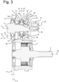
- Figure 3 there is shown a cross section of the input gear train 5, the synchronizer member 7, the output gear train 6, and the clutch member 9 of the PTO transmission 1 according to an embodiment.
- the input gear train 5 may comprise a first input gear 5a and a second input gear 5b coaxially arranged on the input shaft 2, and wherein the synchronizer member 7 is arranged therebetween as shown in Figure 2 .
- the synchronizer member 7 provides a first axial position p1 and a second axial position p2 along the input shaft 2 for connecting the input shaft 2 to the first input gear 5a and the second input gear 5b, respectively.
- the synchronizer member 7 further provides a third axial position N, acting as the aforementioned neutral axial position, wherein the third axial position N is arranged between the first axial position p1 and the second axial position p2 for disconnecting the first input gear 5a and the second input gear 5b from the input shaft 2.
- This embodiment provides a compact but effective way of providing two gear ratios at the first and second axial positions p1, p2 , and where the third axial position N acts as the neutral axial position allowing the input shaft 2 to be disconnected from the input gear train 5 such that the PTO transmission 1 exhibits minimal friction losses when the input shaft 2 is driven whilst the output shaft 3 remains stationary.
- the electric actuator 8 is a linear actuator 8 which is linearly movable along an actuation axis La, wherein the link arrangement 10 is arranged to convert linear movement of the linear actuator 8 along the actuation axis La to movement, i.e. linear movement, of the synchronizer member 7 along the input shaft 2.
- the electric linear actuator 8 allows for accurate control of applied actuation speeds, forces and positions so that the synchronizer member 7 is accurately, reliably and timely positioned along the input shaft 2 for seamlessly connecting the input shaft 2 to the input gear train 5.
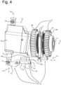
- Figure 4 shows a three dimensional view of a link arrangement 10 connected to the linear electric actuator 8 and the synchronizer member 7 according to an embodiment of the present invention.
- This depicted embodiment exemplifies how linear movement of the linear electric actuator 8 can be converted or transferred to linear movement of the synchronizer member 7 along the input shaft 2 by virtue of the link arrangement 10.
- the link arrangement 10 comprises
- the actuation axis La and the synchronizing axis Ls are perpendicular to the rod axis Lr. This allows the first lever member 12 and the second lever member 14 to rotate in respective planes that are perpendicular to the first rod member 11, and wherein these respective planes can be spatially separated by any required distance along the rod axis Lr.
- Figure 4 shows an embodiment wherein the PTO transmission 1 comprises an actuator housing 15 and wherein the linear actuator 8 moveably extends along the actuation axis La through the actuator housing 15, and wherein the actuator housing 15 is pivotally attached to the casing 4 at a first actuator pivot point 16 and wherein the linear actuator 8 is pivotally attached to the first lever member 12 at a second actuator pivot point 17.
- the actuator housing 15 is able to rotate around the first actuator pivot point 16 in response to linear movement of the linear actuator 8 through the actuator housing 15 and as the second actuator pivot point 17 moves in circular manner in response to rotation of the first lever member 12.
- a pivot axis Lp of the actuator housing 15 intersects the actuator axis La.
- the pivot axis Lp extends through the first actuator pivot point 16 and intersects with actuator axis La. Since actuation forces, e.g. push and pull forces, exerted by the linear actuator 8 extend along the actuator axis La, such actuation forces extend through the first actuator pivot point 16 and as such the actuator housing 15 is not subjected to a clock or counter clockwise moment as the linear actuator 8 pushes or pulls the first lever member 12.
- the link arrangement 10 provides freedom as to the spatial arrangement of the linear actuator 8, e.g. the linear electric actuator 8.
- the actuation axis La may be perpendicular to the input axis Li. So even though the synchronizer member 7 is movable along the input shaft 2, i.e. along the input axis Li, the link arrangement 10 allows the linear electric actuator 8 to be arranged perpendicular to the movement of the synchronizer member 7.
- the synchronizer member 7 acts and operates as a well-known "synchronizer” or “synchromesh” which is configured to seamlessly and smoothly equalise a rotational speed of the input gear train 5 to a rotational speed of the input shaft 2 by utilizing friction as the synchronizer member 7 moves along the input shaft 2 in axial direction.
- the synchronizer member 7 may comprise a shift ring 18 comprising gear teeth along its inner circumference, wherein the shift ring 18 is axially moveable along the input shaft 2. Movement of the shift ring 18 is achieved by a shift fork 19 attached to the second rod member 13 and wherein the shift fork 19 extends, in part, through a circumferential outer groove 18a of the shift ring 18.
- the synchronizer member 7 may further comprise an externally toothed synchronizer hub 20 arranged on the input shaft 2 through splined engagement therewith.
- the synchronizer hub 20 is concentrically arranged in the shift ring 18 and in meshed engagement therewith, and wherein the shift ring 18 is slidable along the synchronizer hub 20 in axial direction.
- first blocking ring 21 and the second blocking ring 23 are provided for both the first input gear 5a and the second input gear 5b there is provided an externally toothed first blocking ring 21 and an externally toothed second blocking ring 23, respectively.
- Each of the first blocking ring 21 and the second blocking ring 23 comprises a conical first inner surface C1 and a conical second inner surface C2 respectively.
- the first and second blocking ring 21, 23 are provided on either side of the shift ring 18 and the synchronizer hub 20, and each of the first and second blocking ring 21, 23 is axially movable along the input shaft 2.
- the shift ring 18 When the shift ring 18 is in the third axial position N, then there is no simultaneous meshed engagement with the synchronizer hub 20 and the first mating gear portion 22 or the second mating gear portion 24. Consequently, the input shaft 2 is disconnected from the input gear train 5, i.e. the first input gear 5a and the second input gear 5b. In the third axial position N the input shaft 2 is able to freely rotate whilst the input gear train 5 may remain stationary, thereby minimizing friction losses of the PTO transmission 1.
- the electric actuator 8 or linear actuator 8 circumvents the use of hydraulic actuation of the synchronizer member 7.
- the clutch member 9 on the other hand may still be operated through hydraulics.
- the PTO transmission 1 comprises a hydraulic pump 25 for operating the clutch member 9, and wherein the hydraulic pump 25 is driven by the input shaft 2 and coaxially arranged thereon.
- the hydraulic pump 25 can be efficiently driven by virtue of the coaxial arrangement of the hydraulic pump 25 on the input shaft 2, so that the use of a chain or belt is not needed, thereby keeping friction losses to a minimum when driving the hydraulic pump 25.
- FIG. 5 shows a schematic diagram of a method of operating the PTO transmission 1, wherein the method for operating the PTO transmission 1 may then comprise the main steps of
- Figure 5 shows further schematic details of operating the synchronizer member 7 as explained earlier.
- the electric actuator 8 may actuate the shift ring 18, which remains in meshed engagement with the synchronizer hub 20, which in turn is connected to the input shaft 2.
- By axial displacement of the shift ring 18 toward the first axial position p1 or the second axial position p2 allows different gear ratios to be selected through:
- disconnecting the input shaft 2 from the input gear train 5 involves the method steps of
- a brake member 3a may be utilized for keeping the output shaft 3 stationary when the synchronizer member 7 is operated, and wherein the brake member 3a may be used in conjunction with the clutch member 9.
- the clutch member 9 is disengaged for disconnecting the output shaft 3 from the output gear train 6 and then to temporarily block the output shaft 3 from rotation by activating the brake member 3a.
- the brake member 3a may be deactivated and the clutch member 9 engaged.
- the electric actuator 8 e.g. the linear electric actuator 8 may be configured for programmable actuation for operating the synchronizer member 7, e.g. the shift ring 18. Furthermore, the electric actuator 8 may be configured for monitoring and/or control of actuation forces applied to the synchronizer member 7.
- Figure 5 depicts an exemplary embodiment wherein the PTO transmission 1 may further comprise a controller 28 which is communicatively connected to the electric actuator 8 and the clutch member 9 for controlled operation thereof.
- the controller 28 may be configured to receive measured forces and/or positions by the electric actuator 8, to process the measured forces and/or positions, and to send instructions to the electric actuator 8 and the clutch member 9 for operation thereof in a required sequency accordingly.
- the controller 28 may also be configured for (de)activating the brake member 3a for (un)blocking the output shaft 3.
- the step of actuating the electric actuator 8 for moving the synchronizer member 7 from the neutral axial position to the connecting axial position may comprise the steps of
- the step of actuating the electric actuator 8 for moving the synchronizer member 7 from the connecting axial position to the neutral axial position comprises the steps of
- these method steps indicate that the electric actuator 8 can be accurately operated by feedback, i.e. measuring actuation forces and/or positions and processing these measured forces and/or positions by the controller 28 for operating the electric actuator 8 to achieve a desired movement of the synchronizer member 7.
Landscapes
- Engineering & Computer Science (AREA)
- General Engineering & Computer Science (AREA)
- Mechanical Engineering (AREA)
- Chemical & Material Sciences (AREA)
- Combustion & Propulsion (AREA)
- Transportation (AREA)
- Mechanical Operated Clutches (AREA)
Applications Claiming Priority (1)
| Application Number | Priority Date | Filing Date | Title |
|---|---|---|---|
| NL2035968A NL2035968B1 (en) | 2023-10-06 | 2023-10-06 | Power take-off transmission |
Publications (1)
| Publication Number | Publication Date |
|---|---|
| EP4534317A1 true EP4534317A1 (fr) | 2025-04-09 |
Family
ID=89157896
Family Applications (1)
| Application Number | Title | Priority Date | Filing Date |
|---|---|---|---|
| EP24202144.2A Pending EP4534317A1 (fr) | 2023-10-06 | 2024-09-24 | Transmission à prise de force |
Country Status (2)
| Country | Link |
|---|---|
| EP (1) | EP4534317A1 (fr) |
| NL (1) | NL2035968B1 (fr) |
Citations (5)
| Publication number | Priority date | Publication date | Assignee | Title |
|---|---|---|---|---|
| US20020043121A1 (en) | 2000-04-07 | 2002-04-18 | Emmanuel Desmarchelier | Multi speed power take off |
| US20070135260A1 (en) * | 2005-12-09 | 2007-06-14 | Omfb S.P.A. Hydraulic Components | Solenoid Device for Engaging Power Takeoffs |
| DE102014013659A1 (de) * | 2014-09-15 | 2016-03-17 | Sticht Technologie Gmbh | Schwenkeinheit und Stelleinheit für ein Getriebe, sowie daraus gebildete Schaltvorrichtung |
| EP3085567A2 (fr) * | 2015-04-20 | 2016-10-26 | ZF Friedrichshafen AG | Pignon prise de force et engin agricole |
| DE102021209053A1 (de) | 2021-08-18 | 2023-02-23 | Zf Friedrichshafen Ag | Betätigungsvorrichtung für ein Getriebeelement |
-
2023
- 2023-10-06 NL NL2035968A patent/NL2035968B1/en active
-
2024
- 2024-09-24 EP EP24202144.2A patent/EP4534317A1/fr active Pending
Patent Citations (5)
| Publication number | Priority date | Publication date | Assignee | Title |
|---|---|---|---|---|
| US20020043121A1 (en) | 2000-04-07 | 2002-04-18 | Emmanuel Desmarchelier | Multi speed power take off |
| US20070135260A1 (en) * | 2005-12-09 | 2007-06-14 | Omfb S.P.A. Hydraulic Components | Solenoid Device for Engaging Power Takeoffs |
| DE102014013659A1 (de) * | 2014-09-15 | 2016-03-17 | Sticht Technologie Gmbh | Schwenkeinheit und Stelleinheit für ein Getriebe, sowie daraus gebildete Schaltvorrichtung |
| EP3085567A2 (fr) * | 2015-04-20 | 2016-10-26 | ZF Friedrichshafen AG | Pignon prise de force et engin agricole |
| DE102021209053A1 (de) | 2021-08-18 | 2023-02-23 | Zf Friedrichshafen Ag | Betätigungsvorrichtung für ein Getriebeelement |
Also Published As
| Publication number | Publication date |
|---|---|
| NL2035968B1 (en) | 2025-04-11 |
Similar Documents
| Publication | Publication Date | Title |
|---|---|---|
| US5078249A (en) | Gear box with gears shiftable under load | |
| EP2883736B1 (fr) | Boîte de transfert entraînée par moteur avec actionnement concentrique | |
| CN102834634B (zh) | 离合器设备 | |
| GB2119459A (en) | Actuation system for transmission synchronizer providing regulated engagement pressure | |
| EP3658802B1 (fr) | Agencement de commande de changement de vitesse dans une boîte de vitesses | |
| US20190085976A1 (en) | Multi-step transmission and control thereof | |
| EP1766252B1 (fr) | Agencements de synchronisation rotatifs ameliores | |
| EP4534317A1 (fr) | Transmission à prise de force | |
| EP2935926A1 (fr) | Agencement d'embrayage comprenant un piston de commande et un boîtier de piston | |
| EP1753966B1 (fr) | Embrayage | |
| EP3430289B1 (fr) | Agencement de commande de changement de vitesse dans une boîte de vitesses | |
| WO2017160220A1 (fr) | Agencement de commande de changement de vitesse dans une boîte de vitesses | |
| EP3864321B1 (fr) | Boîte de vitesses de véhicule et véhicule comprenant une telle boîte de vitesses | |
| JP6504347B2 (ja) | クラッチアクチュエータ | |
| EP2956327B1 (fr) | Ensemble prise de force et synchroniseur combinés | |
| JPWO2020263553A5 (fr) | ||
| JP2003278808A (ja) | 自動変速装置 | |
| SE540153C2 (en) | Changing Gear Ratio in a Gearbox of a Vehicle | |
| KR20070038457A (ko) | 클러치 | |
| CN108953593A (zh) | 用于伺服控制变速箱的控制轴的操作装置 | |
| WO2009070267A1 (fr) | Boîte de vitesse présentant des mécanismes d'embrayage synchronisés | |
| NZ551532A (en) | Clutch |
Legal Events
| Date | Code | Title | Description |
|---|---|---|---|
| PUAI | Public reference made under article 153(3) epc to a published international application that has entered the european phase |
Free format text: ORIGINAL CODE: 0009012 |
|
| STAA | Information on the status of an ep patent application or granted ep patent |
Free format text: STATUS: THE APPLICATION HAS BEEN PUBLISHED |
|
| AK | Designated contracting states |
Kind code of ref document: A1 Designated state(s): AL AT BE BG CH CY CZ DE DK EE ES FI FR GB GR HR HU IE IS IT LI LT LU LV MC ME MK MT NL NO PL PT RO RS SE SI SK SM TR |
|
| STAA | Information on the status of an ep patent application or granted ep patent |
Free format text: STATUS: REQUEST FOR EXAMINATION WAS MADE |
|
| 17P | Request for examination filed |
Effective date: 20250519 |
|
| GRAP | Despatch of communication of intention to grant a patent |
Free format text: ORIGINAL CODE: EPIDOSNIGR1 |
|
| STAA | Information on the status of an ep patent application or granted ep patent |
Free format text: STATUS: GRANT OF PATENT IS INTENDED |
|
| INTG | Intention to grant announced |
Effective date: 20260310 |
|
| RIC1 | Information provided on ipc code assigned before grant |
Ipc: B60K 17/28 20060101AFI20260304BHEP Ipc: F16H 3/089 20060101ALI20260304BHEP Ipc: F16H 63/30 20060101ALI20260304BHEP |