EP4534334A1 - Appareil de conversion de puissance, pile de charge, chargeur embarqué et véhicule électrique - Google Patents
Appareil de conversion de puissance, pile de charge, chargeur embarqué et véhicule électrique Download PDFInfo
- Publication number
- EP4534334A1 EP4534334A1 EP23826358.6A EP23826358A EP4534334A1 EP 4534334 A1 EP4534334 A1 EP 4534334A1 EP 23826358 A EP23826358 A EP 23826358A EP 4534334 A1 EP4534334 A1 EP 4534334A1
- Authority
- EP
- European Patent Office
- Prior art keywords
- voltage
- direct current
- power conversion
- conversion apparatus
- capacitor
- Prior art date
- Legal status (The legal status is an assumption and is not a legal conclusion. Google has not performed a legal analysis and makes no representation as to the accuracy of the status listed.)
- Pending
Links
Images


Classifications
-
- B—PERFORMING OPERATIONS; TRANSPORTING
- B60—VEHICLES IN GENERAL
- B60L—PROPULSION OF ELECTRICALLY-PROPELLED VEHICLES; SUPPLYING ELECTRIC POWER FOR AUXILIARY EQUIPMENT OF ELECTRICALLY-PROPELLED VEHICLES; ELECTRODYNAMIC BRAKE SYSTEMS FOR VEHICLES IN GENERAL; MAGNETIC SUSPENSION OR LEVITATION FOR VEHICLES; MONITORING OPERATING VARIABLES OF ELECTRICALLY-PROPELLED VEHICLES; ELECTRIC SAFETY DEVICES FOR ELECTRICALLY-PROPELLED VEHICLES
- B60L53/00—Methods of charging batteries, specially adapted for electric vehicles; Charging stations or on-board charging equipment therefor; Exchange of energy storage elements in electric vehicles
- B60L53/20—Methods of charging batteries, specially adapted for electric vehicles; Charging stations or on-board charging equipment therefor; Exchange of energy storage elements in electric vehicles characterised by converters located in the vehicle
- B60L53/22—Constructional details or arrangements of charging converters specially adapted for charging electric vehicles
-
- B—PERFORMING OPERATIONS; TRANSPORTING
- B60—VEHICLES IN GENERAL
- B60L—PROPULSION OF ELECTRICALLY-PROPELLED VEHICLES; SUPPLYING ELECTRIC POWER FOR AUXILIARY EQUIPMENT OF ELECTRICALLY-PROPELLED VEHICLES; ELECTRODYNAMIC BRAKE SYSTEMS FOR VEHICLES IN GENERAL; MAGNETIC SUSPENSION OR LEVITATION FOR VEHICLES; MONITORING OPERATING VARIABLES OF ELECTRICALLY-PROPELLED VEHICLES; ELECTRIC SAFETY DEVICES FOR ELECTRICALLY-PROPELLED VEHICLES
- B60L53/00—Methods of charging batteries, specially adapted for electric vehicles; Charging stations or on-board charging equipment therefor; Exchange of energy storage elements in electric vehicles
- B60L53/30—Constructional details of charging stations
- B60L53/31—Charging columns specially adapted for electric vehicles
-
- H—ELECTRICITY
- H02—GENERATION; CONVERSION OR DISTRIBUTION OF ELECTRIC POWER
- H02M—APPARATUS FOR CONVERSION BETWEEN AC AND AC, BETWEEN AC AND DC, OR BETWEEN DC AND DC, AND FOR USE WITH MAINS OR SIMILAR POWER SUPPLY SYSTEMS; CONVERSION OF DC OR AC INPUT POWER INTO SURGE OUTPUT POWER; CONTROL OR REGULATION THEREOF
- H02M1/00—Details of apparatus for conversion
- H02M1/0067—Converter structures employing plural converter units, other than for parallel operation of the units on a single load
- H02M1/0074—Plural converter units whose inputs are connected in series
-
- B—PERFORMING OPERATIONS; TRANSPORTING
- B60—VEHICLES IN GENERAL
- B60L—PROPULSION OF ELECTRICALLY-PROPELLED VEHICLES; SUPPLYING ELECTRIC POWER FOR AUXILIARY EQUIPMENT OF ELECTRICALLY-PROPELLED VEHICLES; ELECTRODYNAMIC BRAKE SYSTEMS FOR VEHICLES IN GENERAL; MAGNETIC SUSPENSION OR LEVITATION FOR VEHICLES; MONITORING OPERATING VARIABLES OF ELECTRICALLY-PROPELLED VEHICLES; ELECTRIC SAFETY DEVICES FOR ELECTRICALLY-PROPELLED VEHICLES
- B60L2210/00—Converter types
- B60L2210/10—DC to DC converters
-
- Y—GENERAL TAGGING OF NEW TECHNOLOGICAL DEVELOPMENTS; GENERAL TAGGING OF CROSS-SECTIONAL TECHNOLOGIES SPANNING OVER SEVERAL SECTIONS OF THE IPC; TECHNICAL SUBJECTS COVERED BY FORMER USPC CROSS-REFERENCE ART COLLECTIONS [XRACs] AND DIGESTS
- Y02—TECHNOLOGIES OR APPLICATIONS FOR MITIGATION OR ADAPTATION AGAINST CLIMATE CHANGE
- Y02T—CLIMATE CHANGE MITIGATION TECHNOLOGIES RELATED TO TRANSPORTATION
- Y02T10/00—Road transport of goods or passengers
- Y02T10/60—Other road transportation technologies with climate change mitigation effect
- Y02T10/70—Energy storage systems for electromobility, e.g. batteries
-
- Y—GENERAL TAGGING OF NEW TECHNOLOGICAL DEVELOPMENTS; GENERAL TAGGING OF CROSS-SECTIONAL TECHNOLOGIES SPANNING OVER SEVERAL SECTIONS OF THE IPC; TECHNICAL SUBJECTS COVERED BY FORMER USPC CROSS-REFERENCE ART COLLECTIONS [XRACs] AND DIGESTS
- Y02—TECHNOLOGIES OR APPLICATIONS FOR MITIGATION OR ADAPTATION AGAINST CLIMATE CHANGE
- Y02T—CLIMATE CHANGE MITIGATION TECHNOLOGIES RELATED TO TRANSPORTATION
- Y02T10/00—Road transport of goods or passengers
- Y02T10/60—Other road transportation technologies with climate change mitigation effect
- Y02T10/7072—Electromobility specific charging systems or methods for batteries, ultracapacitors, supercapacitors or double-layer capacitors
-
- Y—GENERAL TAGGING OF NEW TECHNOLOGICAL DEVELOPMENTS; GENERAL TAGGING OF CROSS-SECTIONAL TECHNOLOGIES SPANNING OVER SEVERAL SECTIONS OF THE IPC; TECHNICAL SUBJECTS COVERED BY FORMER USPC CROSS-REFERENCE ART COLLECTIONS [XRACs] AND DIGESTS
- Y02—TECHNOLOGIES OR APPLICATIONS FOR MITIGATION OR ADAPTATION AGAINST CLIMATE CHANGE
- Y02T—CLIMATE CHANGE MITIGATION TECHNOLOGIES RELATED TO TRANSPORTATION
- Y02T90/00—Enabling technologies or technologies with a potential or indirect contribution to GHG emissions mitigation
- Y02T90/10—Technologies relating to charging of electric vehicles
- Y02T90/12—Electric charging stations
Definitions
- This application provides a power conversion apparatus, a charging pile, an on-board charger, and an electric vehicle, to reduce operating costs of the power conversion apparatus and improve working stability of the power conversion apparatus.
- the second capacitor branch including the film capacitors is used to perform filtering and voltage division on the first voltage.
- the first capacitor branch including the electrolytic capacitor with a large capacitance is used to perform voltage stabilization on the voltage received by the power conversion apparatus. In this case, if any one of the plurality of direct current converters is short-circuited, a film capacitor connected in parallel to an input end of the direct current converter is bypassed. An amplitude of the first voltage obtained through filtering remains unchanged, but a quantity of the film capacitors connected in series is decreased.
- a voltage borne by two ends of a film capacitor connected in parallel to an input end of a non-faulty direct current converter is increased.
- the film capacitor has the high-voltage withstand characteristic, it can still be ensured that the non-faulty direct current converter in the power conversion apparatus can work normally. This improves working stability of the power conversion apparatus.
- costs of the film capacitor are lower than costs of the electrolytic capacitor. This helps reduce operation and maintenance costs of a power conversion circuit when the film capacitor is damaged due to a fault in the direct current converter.
- an electrolytic capacitor may be used to perform voltage stabilization on the voltage received by the power conversion apparatus.
- output ends of the plurality of direct current converters are connected in parallel.
- an embodiment of this application provides a charging pile.
- the charging pile may include a first conversion circuit and the power conversion apparatus according to any one of the first aspect of embodiments of this application and possible designs of the first aspect.
- the first conversion circuit is connected to an external power supply, and converts an alternating current output by the external power supply into a direct current.
- the power conversion apparatus is connected to the first conversion circuit, and is configured to: perform voltage conversion on the direct current output by the first conversion circuit, and supply power to a load by using a direct current obtained through voltage conversion.
- the external power supply may be a utility frequency power grid, and the load may be a vehicle.
- the first conversion circuit is connected to an external power supply, and converts an alternating current output by the external power supply into a direct current.
- the power conversion apparatus is connected to the first conversion circuit, and is configured to: perform voltage conversion on the direct current output by the first conversion circuit, and supply power to a load by using a direct current obtained through voltage conversion.
- the external power supply may be a charging pile, and the load may be a battery of a vehicle.
- an embodiment of this application provides an electric vehicle.
- the electric vehicle includes a high-voltage battery, a low-voltage battery, a low-voltage load, and the power conversion apparatus according to any one of the first aspect of embodiments of this application and the possible designs of the first aspect.
- the high-voltage battery is connected to the power conversion apparatus.
- the power conversion apparatus is separately connected to the low-voltage battery and the low-voltage load.
- the power conversion apparatus is configured to: perform voltage conversion on electric energy output by the high-voltage battery, and supply power to the low-voltage battery and the low-voltage load by using electric energy obtained through voltage conversion.
- connection in embodiments of this application may be understood as an electrical connection, and a connection between two electrical elements may be a direct or indirect connection between the two electrical elements.
- a connection between A and B may mean that A and B are directly connected to each other, or A and B are indirectly connected to each other through one or more other electrical elements.
- the connection between A and B may mean that A is directly connected to C, C is directly connected to B, and A and B are connected to each other through C.
- a “conversion ratio" of a direct current converter in embodiments of this application is a ratio of an input voltage to an output voltage of the direct current converter, or may be understood as a voltage conversion ratio. If the direct current converter performs buck conversion, the output voltage of the direct current converter is less than the input voltage of the direct current converter, and the conversion ratio of the direct current converter is greater than 1. If the direct current converter performs boost conversion, the output voltage of the direct current converter is greater than the input voltage of the direct current converter, and the conversion ratio of the direct current converter is less than 1.
- the power conversion apparatus may be used in an electric vehicle.
- the electric vehicle also referred to as a new energy vehicle, is a vehicle driven by electric energy.
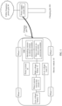
- An electric vehicle 10 mainly includes an on-board charger (on-board charger, OBC) 11, a high-voltage battery 12, a direct current conversion circuit 13, a low-voltage battery 14, a low-voltage load 15, a power system 16, and wheels 17.
- the high-voltage battery 12 and the low-voltage battery 14 each are a battery that can be charged and discharged, for example, a lithium battery or a lead-acid battery.
- a charging pile 201 may be used to charge the electric vehicle 10.
- the alternating current-to-direct current conversion module may convert an alternating current output by the power supply circuit 202 into a direct current, and the direct current-to-direct current conversion module may convert a direct current voltage into a charging voltage of the high-voltage battery 12, and charge the high-voltage battery 12.
- the OBC 11 may further include a high-voltage power distribution unit (power distribution unit, PDU).
- the high-voltage power distribution unit may receive electric energy output by the direct current-to-direct current conversion module, or receive electric energy output by the alternating current-to-direct current conversion module.
- the PDU may allocate and manage the received electric energy.
- the power conversion apparatus is used in a charging pile for an electric vehicle.
- the charging pile 201 mainly includes the power supply circuit 202 and a charging gun 203.
- An input end of the power supply circuit 202 may receive alternating current electric energy provided by a utility frequency power grid 30, and an output end of the power supply circuit 202 is connected to the charging gun 203 through a cable.
- the power supply circuit 202 may convert the received alternating current electric energy into charging electric energy adapted to the electric vehicle 10.
- the charging electric energy obtained through conversion performed by the power supply circuit 202 may be input to the OBC 11 through the charging gun 203.
- the power supply circuit 202 may output alternating current electric energy or direct current electric energy through the charging gun 203.
- a direct current-to-direct current conversion module and a direct current conversion circuit each include a direct current converter formed by a switch component.
- a power conversion capability of a single direct current converter is limited.
- the direct current-to-direct current conversion module is provided with a plurality of direct current converters, and each direct current converter converts a part of power, to improve a power conversion capability of the direct current-to-direct current conversion module, and implement high-power charging of the new energy vehicle.
- each direct current converter is usually connected in parallel to one or more electrolytic capacitors.
- a plurality of electrolytic capacitors form one or more electrolytic capacitor series branches, and perform voltage division on a voltage input by the power supply.
- An input voltage of each direct current converter is determined by a voltage obtained by the electrolytic capacitor connected in parallel. Because the input ends of the N direct current converters are connected in series, input currents of all the direct current converters are the same. Therefore, the electrolytic capacitor may control the input voltage of each direct current converter, to allocate input power to each direct current converter.
- the electrolytic capacitor has a large capacity characteristic, when the direct current-to-direct current conversion module performs conversion, the electrolytic capacitor of a large capacitance can keep an amplitude of an input voltage of the direct current-to-direct current conversion module stable, and then allocate power received by the direct current-to-direct current conversion module to all the direct current converters in equal proportions.
- the power conversion apparatus 30 may be used in an OBC in the electric vehicle, and is used as a direct current-to-direct current conversion module in the OBC to perform voltage conversion on a direct current output by an alternating current-to-direct current conversion module or a charging pile.
- the power conversion apparatus 30 may be fastened to the electric vehicle.
- the power conversion apparatus 30 may alternatively be disposed in a flexible and detachable form, and a fixed interface is provided on the electric vehicle, to implement connection between the power conversion apparatus 30 and a plurality of components in the electric vehicle.
- the power conversion apparatus 30 may be considered as an apparatus independent of the electric vehicle.
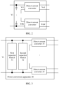
- the first capacitor branch 31 includes the electrolytic capacitors having a large capacity characteristic
- the second capacitor branch 32 includes the film capacitors having a high-voltage withstand characteristic.
- the film capacitors are in the one-to-one correspondence with the direct current converters, and each are connected in parallel to an input end of the corresponding direct current converter, to implement allocation of an input voltage to the corresponding direct current converter 33.
- any one direct current converter 33 in the power conversion apparatus 30 is short-circuited, a film capacitor connected in parallel to an input end of the faulty direct current converter is short-circuited, and a quantity of the film capacitors connected in series in the second capacitor branch 32 is decreased.
- a film capacitor connected in parallel to an input end of a non-faulty direct current converter bears the entire first voltage obtained through filter capacitors. Because the film capacitor has the high-voltage withstand characteristic, the film capacitor connected in parallel to the input end of the non-faulty direct current converter can still work normally in this case, and the non-faulty direct current converter 33 in the power conversion apparatus 30 can still receive a voltage and run. This improves working stability of the power conversion apparatus 30.
- costs of the film capacitor are lower than costs of the electrolytic capacitor. Therefore, operating costs of the power conversion apparatus 30 can also be reduced when there are an excessive quantity of short-circuited direct current converters and consequently film capacitors are damaged due to a high voltage.
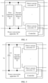
- Two ends of the first capacitor branch 31 are connected to two ports of an input end of the power conversion apparatus 30, and the first capacitor branch 31 perform voltage stabilization on the voltage received by the input end of the power conversion apparatus 30, to obtain the first voltage.
- a withstand voltage of the first electrolytic capacitor C1 can meet a requirement of the power conversion apparatus 30 for an amplitude of a received voltage, and a capacitance of the first electrolytic capacitor C1 may meet a requirement of the power conversion apparatus 30 for a received power.
- the two ends of the first capacitor branch 31 are connected in parallel to a resistor branch, and the resistor branch includes a plurality of first resistors R1 connected in series.
- a first end of a 1 st first resistor R1 in the plurality of first resistors R1 is connected to the first end of the 1 st second electrolytic capacitor C2 in the first capacitor branch 31, and a second end of a last first resistor R1 in the plurality of first resistors R1 is connected to the second end of the last second electrolytic capacitor C2 in the first capacitor branch 31.
- a resistance of the first resistor R1 connected in parallel to the second electrolytic capacitor C2 may be adjusted, to control a voltage of each second electrolytic capacitor C2 to be a required voltage.
- a voltage equalization circuit is disposed at the two ends of the first capacitor branch 31, and the voltage equalization circuit is configured to equalize a voltage at two ends of each second electrolytic capacitor C2 in the first capacitor branch 31.
- the second capacitor branch 32 includes the plurality of film capacitors C3 connected in series, and the film capacitors C3 are in a one-to-one correspondence with the direct current converters 33 in the power conversion apparatus 30.
- a first end of a 1 st film capacitor C3 in the plurality of film capacitors C3 is connected to the first end of the first capacitor branch 31
- a second end of a last film capacitor C3 in the plurality of film capacitors C3 is connected to the second end of the first capacitor branch 31
- each film capacitor C3 is connected in parallel to an input end of the corresponding direct current converter 33.
- the film capacitor C3 is connected in parallel to the input end of the corresponding direct current converter 33 and the plurality of film capacitors C3 are connected in series, input ends of the plurality of direct current converters 33 are connected in series. Therefore, currents received by the input ends of all the direct current converter 33 are the same. Power received by each direct current converter 33 is determined by a voltage received by the direct current converter 33, and the voltage received by the direct current converter 33 is determined by the second voltage obtained by the corresponding film capacitor C3. Therefore, the power received by the direct current converter can be adjusted by adjusting a parameter of the film capacitor that is in the second capacitor branch 32 and that corresponds to the direct current converter 33.
- the first capacitor branch 31 includes four film capacitors C3 connected in series.
- a voltage obtained by the film capacitor C3 is 25 V. Because the film capacitor C3 has a high-voltage withstand characteristic, the film voltages C3 can still work normally in this case, to ensure that direct current converters 33 corresponding to the film capacitors can work normally. This improves working stability of the power conversion apparatus 30.
- Costs of the film capacitor C3 are lower than costs of the electrolytic capacitor. Therefore, running costs of the power conversion apparatus 30 can be reduced when there are a large quantity of faulty direct current converters in the power conversion apparatus 30 and consequently a voltage at two ends of a film capacitor corresponding to a non-faulty direct current converter exceeds a maximum withstand voltage of the film capacitor.
- the input ends of the plurality of direct current converters 33 are connected in series.
- a first input end of the 1 st direct current converter 33 of the plurality of direct current converters 33 is connected to the first end of the first capacitor branch 31 and the first end of the second capacitor branch 32, and a second input end of the last direct current converter 33 of the plurality of direct current converters 33 is connected to the second end of the first capacitor branch 31 and the second end of the second capacitor branch 32.
- the direct current converter 33 may use an existing structure.
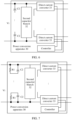
- the direct current converter 33 may use an H-bridge rectifier circuit.
- a first end of a first bridge arm and a first end of a second bridge arm in the H-bridge rectifier circuit form a first input end of the direct current converter 33.
- a second end of the first bridge arm and a second end of the second bridge arm in the H-bridge rectifier circuit 33 form a second input end of the direct current converter 33.
- An intermediate node of the first bridge arm in the H-bridge rectifier circuit forms a first output end of the direct current converter 33.
- An intermediate node of the second bridge arm in the H-bridge rectifier circuit forms a second output end of the direct current converter 33.
- the direct current converter 33 may be connected to two ends of a corresponding film capacitor through the first input end and the second input end of the direct current converter 33, and receive a second voltage output by the corresponding film capacitor.
- the direct current converter 33 outputs, to a connected device through the first output end and the second output end of the direct current converter 33, electric energy obtained through voltage conversion.
- the direct current converter 33 may perform voltage adjustment on electric energy output by the corresponding film capacitor, and output a supply voltage required by the device connected to the direct current converter 33.
- a and B are used as input ends and are configured to receive a second voltage output by the corresponding film capacitor
- C and D are used as output ends and are configured to: output a voltage obtained through voltage adjustment performed by the MOS transistors Q1/Q2/Q3/Q4, and supply power to or charge the connected device.
- the direct current converter 33 When the direct current converter 33 is short-circuited, a film capacitor C3 connected in parallel to the input end of the direct current converter 33 is short-circuited. In this case, the faulty direct current converter is bypassed from a series branch to which the direct current converter 33 belongs, to ensure that a non-faulty direct current converter can work normally.
- the MOS transistors Q1 and Q2 may be controlled to be turned on, so that the faulty direct current converter is bypassed from a direct current converter connected in series, to ensure the non-faulty direct current converter can work normally.
- the power conversion apparatus 30 is used in an electric vehicle, and is used as a direct current-to-direct current conversion module of an OBC in the electric vehicle.
- the output ends of all the direct current converters 33 in the power conversion apparatus 30 are connected in parallel, and are connected to a high-voltage battery, to charge the high-voltage battery.
- the first output end of the 1 st direct current converter in the plurality of direct current converters 33 is connected to a positive electrode of the high-voltage battery, and the second output end of the last direct current converter in the plurality of direct current converters 33 is connected to a negative electrode of the high-voltage battery.
- the power conversion apparatus 30 is used in an electric vehicle.
- the power conversion apparatus 30 is connected between a high-voltage battery and a low-voltage battery, and is connected between the high-voltage battery and a low-voltage load.
- the power conversion apparatus may convert a voltage input by the high-voltage battery into a charging voltage of the low-voltage battery and a supply voltage of the low-voltage load.
- the plurality of direct current converters 33 are connected to different components. For example, an output end of the 1 st direct current converter is connected to the low-voltage battery, an output end of the 2 nd direct current converter is connected to a first low-voltage load, and so on, to power supply to or charge all the components.
- the direct current converter may use another circuit structure, for example, a half-bridge rectifier circuit, an inductor-inductor-capacitor (inductor-inductor-capacitor, LLC) resonant conversion circuit, a forward circuit, a flyback circuit, a voltage-adjustable boost (Boost) circuit, a voltage-adjustable buck (Buck) circuit, or a buck-boost circuit.
- Boost voltage-adjustable boost
- Buck voltage-adjustable buck
- the direct current converter 33 may include components such as a switching transistor, a diode, an inductor, a capacitor, and the like.
- a working status and a conversion ratio of the direct current converter may be implemented by adjusting working statuses of the components (for example, the switching transistor).
- the controller may be connected to a gate of the MOS transistor.
- the controller may control the MOS transistor to be turned on or turned off, so that the direct current converter adjusts a voltage received by an input end of the direct current converter, and supplies power to or charges a connected device.
- the switching transistor in the direct current converter 33 is a BJT
- the controller may be connected to a base of the BJT.
- the controller may control the BJT to be turned on or turned off, so that the direct current converter adjusts a voltage received by an input end of the direct current converter, and supplies power to or charges a connected device.
- the power conversion apparatus 30 further includes a detection apparatus.
- the detection apparatus may be connected to the direct current converter in the power conversion apparatus 30.
- the detection apparatus may detect the working status of the direct current converter.
- the detection apparatus may generate, to the controller, a first signal indicating that the direct current converter is faulty.
- the controller adjusts a drive signal that is to be output to a switching transistor in a non-faulty direct current converter, to adjust a conversion ratio of the non-faulty direct current converter.
- the direct current converter outputs a supply voltage or a charging voltage that meets a requirement of a connected device for a voltage.
- the detection apparatus may detect an output current and an output voltage of the direct current converter and determine the working status of the direct current converter by using the detected output current and output voltage.
- the controller in the power conversion apparatus 30 is further connected to an external detection apparatus.
- the controller adjusts a drive signal that is to be output to a switching transistor in a non-faulty direct current converter, to adjust a conversion ratio of the non-faulty direct current converter.
- the direct current converter outputs a supply voltage that meets a requirement of a connected device for a voltage.
- the controller can maintain running of the power conversion apparatus 30 only when a single direct current converter is faulty or a few direct current converters are faulty.
- the power conversion apparatus may further include a protector.
- the protector may be connected to the first end of the first capacitor branch 31 and the first end of the second capacitor branch 32. The protector may detect a voltage or a current received by the power conversion apparatus.
- the external power supply may be a utility frequency power grid.
- the first conversion circuit may convert an alternating current of the utility frequency power grid into a direct current
- the power conversion apparatus may convert the voltage of the direct current output by the first conversion circuit into a charging voltage of a vehicle, to charge the vehicle.
- an embodiment of this application further provides an on-board charger.
- the on-board charger includes a first conversion circuit and the foregoing power conversion apparatus 30.
- the on-board charger in this application may include only the power conversion apparatus.
- the power conversion apparatus may directly convert a direct current obtained from the charging pile into a charging voltage of the high-voltage battery, and charge the high-voltage battery.
- the electric vehicle may include a high-voltage battery, a low-voltage battery, a low-voltage load, and the foregoing power conversion apparatus 30.
- the high-voltage battery is connected to the power conversion apparatus, and is configured to output stored electric energy to the power conversion apparatus.
- the power conversion apparatus is separately connected to the low-voltage battery and the low-voltage load, and is configured to perform voltage conversion on electric energy output by the high-voltage battery, and supply power to the low-voltage battery and the low-voltage load by using electric energy obtained through voltage conversion.
Landscapes
- Engineering & Computer Science (AREA)
- Power Engineering (AREA)
- Transportation (AREA)
- Mechanical Engineering (AREA)
- Dc-Dc Converters (AREA)
Applications Claiming Priority (2)
| Application Number | Priority Date | Filing Date | Title |
|---|---|---|---|
| CN202210707553.5A CN115179789B (zh) | 2022-06-21 | 2022-06-21 | 功率转换装置、充电桩、车载充电器和电动汽车 |
| PCT/CN2023/101120 WO2023246710A1 (fr) | 2022-06-21 | 2023-06-19 | Appareil de conversion de puissance, pile de charge, chargeur embarqué et véhicule électrique |
Publications (2)
| Publication Number | Publication Date |
|---|---|
| EP4534334A1 true EP4534334A1 (fr) | 2025-04-09 |
| EP4534334A4 EP4534334A4 (fr) | 2025-10-22 |
Family
ID=83515679
Family Applications (1)
| Application Number | Title | Priority Date | Filing Date |
|---|---|---|---|
| EP23826358.6A Pending EP4534334A4 (fr) | 2022-06-21 | 2023-06-19 | Appareil de conversion de puissance, pile de charge, chargeur embarqué et véhicule électrique |
Country Status (4)
| Country | Link |
|---|---|
| US (1) | US20250121717A1 (fr) |
| EP (1) | EP4534334A4 (fr) |
| CN (1) | CN115179789B (fr) |
| WO (1) | WO2023246710A1 (fr) |
Families Citing this family (2)
| Publication number | Priority date | Publication date | Assignee | Title |
|---|---|---|---|---|
| CN115179789B (zh) * | 2022-06-21 | 2025-11-11 | 华为数字能源技术有限公司 | 功率转换装置、充电桩、车载充电器和电动汽车 |
| CN117277525B (zh) * | 2023-09-26 | 2024-01-16 | 吉林省艾特网络传媒有限公司 | 一种用于充电桩的智能功率控制系统 |
Family Cites Families (16)
| Publication number | Priority date | Publication date | Assignee | Title |
|---|---|---|---|---|
| TW200737677A (en) * | 2006-03-24 | 2007-10-01 | Hon Hai Prec Ind Co Ltd | Power supply device with inrush current limiting circuit |
| US9166489B2 (en) * | 2009-02-27 | 2015-10-20 | Delta Electronics (Shanghai) Co., Ltd. | Layouts of multiple transformers and multiple rectifiers of interleaving converter |
| CN101710716A (zh) * | 2009-11-13 | 2010-05-19 | 南京航空航天大学 | 能减小电解电容的并网逆变器 |
| KR20130078386A (ko) * | 2011-12-30 | 2013-07-10 | 엘에스산전 주식회사 | 전기자동차 충전기용 dc-dc 컨버터 |
| CN102723870B (zh) * | 2012-06-21 | 2015-07-08 | 中国矿业大学(北京) | 串联输入串联输出全桥高频隔离双向dc/dc变换器 |
| CN202978409U (zh) * | 2012-11-07 | 2013-06-05 | 麦思博尔能源技术(天津)有限公司 | 基于超级电容的动力ups系统 |
| WO2015005155A1 (fr) * | 2013-07-08 | 2015-01-15 | 株式会社村田製作所 | Circuit de conversion de puissance, système de transmission de puissance et système de conversion de puissance |
| CN104852588A (zh) * | 2015-06-09 | 2015-08-19 | 黑龙江大学 | 适合高压输入多输出场合的辅助电源 |
| CN105356758A (zh) * | 2015-12-03 | 2016-02-24 | 东北电力大学 | 一种高频隔离型dc-dc双级功率变换系统结构 |
| CN206379884U (zh) * | 2016-12-02 | 2017-08-04 | 安徽博微智能电气有限公司 | 一种dcdc电源 |
| WO2019082018A1 (fr) * | 2017-10-27 | 2019-05-02 | Silanna Asia Pte Ltd | Convertisseur à transfert direct à diviseur de tension fusionnée |
| CN110356268B (zh) * | 2019-06-25 | 2021-08-03 | 华为技术有限公司 | 一种车载充放电装置和系统 |
| CN213072477U (zh) * | 2020-07-28 | 2021-04-27 | 苏州创泰电子有限公司 | 直流电源电路 |
| CN112103920A (zh) * | 2020-09-10 | 2020-12-18 | 安徽鸿创新能源动力有限公司 | 一种dc/dc转换器过流保护电路 |
| CN114531037B (zh) * | 2022-01-26 | 2024-05-03 | 中国科学院电工研究所 | 一种直流变压器电流断续控制方法 |
| CN115179789B (zh) * | 2022-06-21 | 2025-11-11 | 华为数字能源技术有限公司 | 功率转换装置、充电桩、车载充电器和电动汽车 |
-
2022
- 2022-06-21 CN CN202210707553.5A patent/CN115179789B/zh active Active
-
2023
- 2023-06-19 EP EP23826358.6A patent/EP4534334A4/fr active Pending
- 2023-06-19 WO PCT/CN2023/101120 patent/WO2023246710A1/fr not_active Ceased
-
2024
- 2024-12-20 US US18/990,719 patent/US20250121717A1/en active Pending
Also Published As
| Publication number | Publication date |
|---|---|
| CN115179789A (zh) | 2022-10-14 |
| US20250121717A1 (en) | 2025-04-17 |
| WO2023246710A1 (fr) | 2023-12-28 |
| EP4534334A4 (fr) | 2025-10-22 |
| CN115179789B (zh) | 2025-11-11 |
Similar Documents
| Publication | Publication Date | Title |
|---|---|---|
| EP3795409B1 (fr) | Système de puissance et dispositif d'alimentation électrique | |
| US9873341B2 (en) | Transformerless, current-isolated onboard charger with solid-state switching controls | |
| US11161424B2 (en) | On-board vehicle electrical system for charging an electrically operated vehicle, and method | |
| EP2773014B1 (fr) | Système d'accumulateur | |
| US20250121717A1 (en) | Power conversion apparatus, charging pile, on-board charger, and electric vehicle | |
| US20220231537A1 (en) | Conversion device, conversion system, switching device, vehicle including the same, and control method | |
| US10625622B2 (en) | Power supply device of vehicle | |
| US9718376B2 (en) | Electricity supply system having double power-storage devices of a hybrid or electric motor vehicle | |
| EP2472702A1 (fr) | Système d'alimentation en énergie pour véhicule | |
| US20120280655A1 (en) | Charging system for electric vehicles | |
| US20140239869A1 (en) | Electrical System | |
| US20200406769A1 (en) | Multilevel motor drive with integrated battery charger | |
| KR20140040108A (ko) | 에너지 저장 장치의 충전 | |
| JP2013539955A (ja) | エネルギー供給網、およびエネルギー供給網にある直流電圧中間回路用のエネルギー蓄積器として用いられる少なくとも1つのエネルギー蓄積器セルに充電する方法 | |
| US12051966B2 (en) | Converter and on-board charger | |
| CN116094011A (zh) | 储能系统 | |
| US9490710B2 (en) | Power supply device for supplying power to a load by combining a secondary battery and a capacitor | |
| CN204290428U (zh) | 一种集成电机驱动和电池充电功能模块 | |
| US20200106320A1 (en) | Drive system | |
| CN103296910B (zh) | 储能装置的直流电压截取装置和由储能装置生成直流电压的方法 | |
| CN103296900B (zh) | 储能装置的直流电压截取装置和由储能装置生成直流电压的方法 | |
| JP7711546B2 (ja) | 充電装置 | |
| CN106655294A (zh) | 用于车辆的充电转换装置和充电转换方法 | |
| JP7559617B2 (ja) | 電源装置 | |
| JP7643285B2 (ja) | 充電装置 |
Legal Events
| Date | Code | Title | Description |
|---|---|---|---|
| STAA | Information on the status of an ep patent application or granted ep patent |
Free format text: STATUS: THE INTERNATIONAL PUBLICATION HAS BEEN MADE |
|
| PUAI | Public reference made under article 153(3) epc to a published international application that has entered the european phase |
Free format text: ORIGINAL CODE: 0009012 |
|
| STAA | Information on the status of an ep patent application or granted ep patent |
Free format text: STATUS: REQUEST FOR EXAMINATION WAS MADE |
|
| 17P | Request for examination filed |
Effective date: 20250103 |
|
| AK | Designated contracting states |
Kind code of ref document: A1 Designated state(s): AL AT BE BG CH CY CZ DE DK EE ES FI FR GB GR HR HU IE IS IT LI LT LU LV MC ME MK MT NL NO PL PT RO RS SE SI SK SM TR |
|
| DAV | Request for validation of the european patent (deleted) | ||
| DAX | Request for extension of the european patent (deleted) | ||
| A4 | Supplementary search report drawn up and despatched |
Effective date: 20250923 |
|
| RIC1 | Information provided on ipc code assigned before grant |
Ipc: B60L 53/31 20190101AFI20250917BHEP Ipc: B60L 53/22 20190101ALI20250917BHEP Ipc: H02M 3/335 20060101ALI20250917BHEP Ipc: H02J 7/00 20060101ALI20250917BHEP Ipc: H02M 1/00 20060101ALI20250917BHEP |