EP4534351A1 - Activation et optimisation d'un mode de nuit dans des applications de surveillance de caméra - Google Patents
Activation et optimisation d'un mode de nuit dans des applications de surveillance de caméra Download PDFInfo
- Publication number
- EP4534351A1 EP4534351A1 EP24203467.6A EP24203467A EP4534351A1 EP 4534351 A1 EP4534351 A1 EP 4534351A1 EP 24203467 A EP24203467 A EP 24203467A EP 4534351 A1 EP4534351 A1 EP 4534351A1
- Authority
- EP
- European Patent Office
- Prior art keywords
- image data
- received
- view
- vehicle
- signal
- Prior art date
- Legal status (The legal status is an assumption and is not a legal conclusion. Google has not performed a legal analysis and makes no representation as to the accuracy of the status listed.)
- Pending
Links
Images


Classifications
-
- H—ELECTRICITY
- H04—ELECTRIC COMMUNICATION TECHNIQUE
- H04N—PICTORIAL COMMUNICATION, e.g. TELEVISION
- H04N23/00—Cameras or camera modules comprising electronic image sensors; Control thereof
- H04N23/70—Circuitry for compensating brightness variation in the scene
- H04N23/76—Circuitry for compensating brightness variation in the scene by influencing the image signals
-
- B—PERFORMING OPERATIONS; TRANSPORTING
- B60—VEHICLES IN GENERAL
- B60K—ARRANGEMENT OR MOUNTING OF PROPULSION UNITS OR OF TRANSMISSIONS IN VEHICLES; ARRANGEMENT OR MOUNTING OF PLURAL DIVERSE PRIME-MOVERS IN VEHICLES; AUXILIARY DRIVES FOR VEHICLES; INSTRUMENTATION OR DASHBOARDS FOR VEHICLES; ARRANGEMENTS IN CONNECTION WITH COOLING, AIR INTAKE, GAS EXHAUST OR FUEL SUPPLY OF PROPULSION UNITS IN VEHICLES
- B60K35/00—Instruments specially adapted for vehicles; Arrangement of instruments in or on vehicles
- B60K35/20—Output arrangements, i.e. from vehicle to user, associated with vehicle functions or specially adapted therefor
- B60K35/21—Output arrangements, i.e. from vehicle to user, associated with vehicle functions or specially adapted therefor using visual output, e.g. blinking lights or matrix displays
- B60K35/22—Display screens
-
- B—PERFORMING OPERATIONS; TRANSPORTING
- B60—VEHICLES IN GENERAL
- B60K—ARRANGEMENT OR MOUNTING OF PROPULSION UNITS OR OF TRANSMISSIONS IN VEHICLES; ARRANGEMENT OR MOUNTING OF PLURAL DIVERSE PRIME-MOVERS IN VEHICLES; AUXILIARY DRIVES FOR VEHICLES; INSTRUMENTATION OR DASHBOARDS FOR VEHICLES; ARRANGEMENTS IN CONNECTION WITH COOLING, AIR INTAKE, GAS EXHAUST OR FUEL SUPPLY OF PROPULSION UNITS IN VEHICLES
- B60K35/00—Instruments specially adapted for vehicles; Arrangement of instruments in or on vehicles
- B60K35/80—Arrangements for controlling instruments
- B60K35/81—Arrangements for controlling instruments for controlling displays
-
- B—PERFORMING OPERATIONS; TRANSPORTING
- B60—VEHICLES IN GENERAL
- B60R—VEHICLES, VEHICLE FITTINGS, OR VEHICLE PARTS, NOT OTHERWISE PROVIDED FOR
- B60R1/00—Optical viewing arrangements; Real-time viewing arrangements for drivers or passengers using optical image capturing systems, e.g. cameras or video systems specially adapted for use in or on vehicles
- B60R1/20—Real-time viewing arrangements for drivers or passengers using optical image capturing systems, e.g. cameras or video systems specially adapted for use in or on vehicles
- B60R1/22—Real-time viewing arrangements for drivers or passengers using optical image capturing systems, e.g. cameras or video systems specially adapted for use in or on vehicles for viewing an area outside the vehicle, e.g. the exterior of the vehicle
-
- H—ELECTRICITY
- H04—ELECTRIC COMMUNICATION TECHNIQUE
- H04N—PICTORIAL COMMUNICATION, e.g. TELEVISION
- H04N23/00—Cameras or camera modules comprising electronic image sensors; Control thereof
- H04N23/60—Control of cameras or camera modules
- H04N23/667—Camera operation mode switching, e.g. between still and video, sport and normal or high- and low-resolution modes
-
- H—ELECTRICITY
- H04—ELECTRIC COMMUNICATION TECHNIQUE
- H04N—PICTORIAL COMMUNICATION, e.g. TELEVISION
- H04N23/00—Cameras or camera modules comprising electronic image sensors; Control thereof
- H04N23/60—Control of cameras or camera modules
- H04N23/695—Control of camera direction for changing a field of view, e.g. pan, tilt or based on tracking of objects
-
- H—ELECTRICITY
- H04—ELECTRIC COMMUNICATION TECHNIQUE
- H04N—PICTORIAL COMMUNICATION, e.g. TELEVISION
- H04N23/00—Cameras or camera modules comprising electronic image sensors; Control thereof
- H04N23/70—Circuitry for compensating brightness variation in the scene
- H04N23/71—Circuitry for evaluating the brightness variation
-
- H—ELECTRICITY
- H04—ELECTRIC COMMUNICATION TECHNIQUE
- H04N—PICTORIAL COMMUNICATION, e.g. TELEVISION
- H04N23/00—Cameras or camera modules comprising electronic image sensors; Control thereof
- H04N23/70—Circuitry for compensating brightness variation in the scene
- H04N23/72—Combination of two or more compensation controls
-
- H—ELECTRICITY
- H04—ELECTRIC COMMUNICATION TECHNIQUE
- H04N—PICTORIAL COMMUNICATION, e.g. TELEVISION
- H04N23/00—Cameras or camera modules comprising electronic image sensors; Control thereof
- H04N23/80—Camera processing pipelines; Components thereof
- H04N23/81—Camera processing pipelines; Components thereof for suppressing or minimising disturbance in the image signal generation
-
- B—PERFORMING OPERATIONS; TRANSPORTING
- B60—VEHICLES IN GENERAL
- B60K—ARRANGEMENT OR MOUNTING OF PROPULSION UNITS OR OF TRANSMISSIONS IN VEHICLES; ARRANGEMENT OR MOUNTING OF PLURAL DIVERSE PRIME-MOVERS IN VEHICLES; AUXILIARY DRIVES FOR VEHICLES; INSTRUMENTATION OR DASHBOARDS FOR VEHICLES; ARRANGEMENTS IN CONNECTION WITH COOLING, AIR INTAKE, GAS EXHAUST OR FUEL SUPPLY OF PROPULSION UNITS IN VEHICLES
- B60K2360/00—Indexing scheme associated with groups B60K35/00 or B60K37/00 relating to details of instruments or dashboards
- B60K2360/16—Type of output information
- B60K2360/176—Camera images
-
- B—PERFORMING OPERATIONS; TRANSPORTING
- B60—VEHICLES IN GENERAL
- B60K—ARRANGEMENT OR MOUNTING OF PROPULSION UNITS OR OF TRANSMISSIONS IN VEHICLES; ARRANGEMENT OR MOUNTING OF PLURAL DIVERSE PRIME-MOVERS IN VEHICLES; AUXILIARY DRIVES FOR VEHICLES; INSTRUMENTATION OR DASHBOARDS FOR VEHICLES; ARRANGEMENTS IN CONNECTION WITH COOLING, AIR INTAKE, GAS EXHAUST OR FUEL SUPPLY OF PROPULSION UNITS IN VEHICLES
- B60K2360/00—Indexing scheme associated with groups B60K35/00 or B60K37/00 relating to details of instruments or dashboards
- B60K2360/20—Optical features of instruments
- B60K2360/21—Optical features of instruments using cameras
-
- B—PERFORMING OPERATIONS; TRANSPORTING
- B60—VEHICLES IN GENERAL
- B60K—ARRANGEMENT OR MOUNTING OF PROPULSION UNITS OR OF TRANSMISSIONS IN VEHICLES; ARRANGEMENT OR MOUNTING OF PLURAL DIVERSE PRIME-MOVERS IN VEHICLES; AUXILIARY DRIVES FOR VEHICLES; INSTRUMENTATION OR DASHBOARDS FOR VEHICLES; ARRANGEMENTS IN CONNECTION WITH COOLING, AIR INTAKE, GAS EXHAUST OR FUEL SUPPLY OF PROPULSION UNITS IN VEHICLES
- B60K2360/00—Indexing scheme associated with groups B60K35/00 or B60K37/00 relating to details of instruments or dashboards
- B60K2360/20—Optical features of instruments
- B60K2360/33—Illumination features
- B60K2360/349—Adjustment of brightness
-
- B—PERFORMING OPERATIONS; TRANSPORTING
- B60—VEHICLES IN GENERAL
- B60R—VEHICLES, VEHICLE FITTINGS, OR VEHICLE PARTS, NOT OTHERWISE PROVIDED FOR
- B60R2300/00—Details of viewing arrangements using cameras and displays, specially adapted for use in a vehicle
- B60R2300/30—Details of viewing arrangements using cameras and displays, specially adapted for use in a vehicle characterised by the type of image processing
Definitions
- the invention relates to a method for operating an image data processing device of a vision system of a vehicle, a vision system with a respective image data processing device, and a vehicle with a respective vision system.
- Such camera-monitor systems typically comprise a monitor device connected to at least one camera device.
- the at least one camera device is, thereby, usually configured to capture image data of the vehicle's surroundings, which is then displayed on the monitor device arranged within the vehicle.
- the image quality i.e. image signal processor (ISP)
- ISP image signal processor
- a known approach to address this problem is to modify the operation settings of the monitor device, for example, by reducing the display brightness of the monitor device for night condition (dimming). Via decreasing the power of an LED backlight located behind the display, it is possible to prevent the driver of getting tired or getting distracted by a bright screen at night.
- the image content itself is usually not improved or adjusted. Consequently, the image quality factors (key performance indicators), such as color noise, dynamic range, exposure and/or white balance will remain insufficient.
- the objective of the invention is to provide an improved way of providing image data, e.g. to a driver of a vehicle, preferably avoiding the disadvantages of conventional techniques.
- the image data processing device is an image data processing device of a vision system (e.g. a mirror replacement system) of a vehicle.
- a vision system e.g. a mirror replacement system
- the method comprises receiving image data captured by at least one imaging device.
- the at least one imaging device may be part of the vehicle and/or the vision system of the vehicle.
- the at least one imaging device may include one camera or several cameras, e.g. mounted on the vehicle.
- the image data comprises rearward view image data captured (e.g. laterally) aside and/or behind of the vehicle.
- the at least one imaging device may be configured to capture a class II view, a class IV view and/or a class V view according to the Directives 2003/97/EC and 2007/38/EC.
- the method further comprises receiving a condition-signal, preferably indicating a day-time condition or a night-time condition.
- the condition-signal may be generated by a condition device of the vehicle and/or the vision system of the vehicle.
- the condition device may be a brightness and/or light sensor.
- the brightness and/or light sensor may be configured to output a first condition-signal value indicating a day-time condition, when a brightness of the vehicle's surroundings is above a predefined value and to output a second condition-signal value indicating a night-time condition, when the brightness of the vehicle's surroundings is below that predefined value.
- the method further comprises (e.g. automatically) processing (e.g. post-processing) the received image data (e.g. by the image data processing device) dependent on the received condition-signal. Consequently, the way the received image data are processed may differ depending on the received condition-signal, in particular, on whether said condition-signal indicates the day-time condition or the night-time condition.
- the step of processing may comprise altering and/or changing image processing settings based on the received condition-signal.
- the step of processing may comprise adjusting a contrast and/or a brightness of the received image data.
- the method further comprises outputting the processed image data, e.g. to a display device.
- the current solution advantageously adjusts the image content itself by respective processing of the captured image data.
- This enables advantageously much greater flexibility in actively modifying the image data by the image data processing device compared to a simple adjustment of the display appearance via the monitor device.
- the image quality can be (e.g. automatically) optimized to a greater extent for the respective situation, which allows for a better adaption of the provided image data to the current needs of the driver.
- the step of processing may differ depending on whether the received condition-signal indicates the day-time condition or the night-time condition.
- the step of processing may comprise a day mode and a night mode.
- the image processing settings used for processing the received image data differ dependent on whether the night-time condition (e.g. night mode) or day-time condition (e.g. day mode) is met or present.
- a contrast, digital gain and/or white balance of the received image data may be altered based on the received condition-signal and/or present (e.g. day or night) mode.
- this allows for adapting the image data to the current ambient light condition.
- the step of processing may comprise adjusting (e.g. enhancing and/or reducing) a contrast of the received image data.
- contrast may, for example, refer to the difference between light and dark areas of the image data. Adjusting the contrast may be performed globally (e.g. influencing the whole tonal range of the image data) and/or locally (e.g. influencing regions of the image data independently).
- the step of processing may comprise adjusting (e.g. increasing and/or decreasing) a digital gain of the received image data.
- digital gain may, for example, refer to a factor by which the image data is amplified after the digitizing process of the at least one imaging device.
- analogue gain or gain may refer to the magnitude of amplification of an output voltage of the photodetectors of the at least one imaging device before sampling by an analogue digital converter.
- the step of processing may comprise adjusting (e.g. increasing and/or decreasing) a noise filtering of the received image data.
- adjusting e.g. increasing and/or decreasing
- a noise filtering of the received image data may be adjusted by using a per se known de-noising algorithm, like a spatial domain filter and/or Wiener filter.
- the term noise filtering may, for example, refer to remove noise from the image data, in particular, to restore the "true" image.
- the adjusting of the noise filtering includes altering a degree to which noise filtering is used and/or whether it is used at all.
- the method may further comprise outputting (e.g. by the image data processing device) a control-signal for the at least one imaging device dependent on the received condition-signal.
- the control-signal may cause the at least one imaging device to adjust at least one image capture setting (e.g. a frame rate, a (analogue) gain, an exposure time, and/or exposure threshold) of the at least one imaging device.
- the outputted control-signal may cause the at least one imaging device to decrease the frame rate (e.g. from 50 fps to 25 fps) and/or to increase the exposure time.
- this aspect advantageously allows for actively modifying the way the (e.g. raw) image data is captured, thus further increasing the flexibility for adapting/optimizing the image quality for the current conditions.
- the method may further comprise receiving a situation-signal.
- the situation-signal may be generated by a situation detection device of the vehicle and/or the vision system of the vehicle.
- the situation-signal may indicate a current speed of the vehicle, a gear selection of the vehicle (e.g. forward or reverse), and/or an operating state of the vehicle (e.g. manoeuvring, cornering, and/or motorway driving).
- the step of processing is further dependent on the received situation-signal.
- the processing of the received image data may, therefore, depend on the received condition-signal and the received situation-signal.
- the processing within the night mode may differ on whether the vehicle is reverse parking or travelling on a motorway.
- the contrast and brightness of the image data may be enhanced by the image data processing device (e.g. so that the driver can see as many details as possible)
- the contrast and brightness of the image data may be lowered (e.g. so that the driver gets less distracted).
- this allows for adjusting the image quality optimally to the respective driving situation, such that the situational awareness of the driver for various scenarios can be improved.
- the step of processing may comprise reducing a contrast, a digital gain, and/or a brightness of the received image data, when the received situation-signal indicates a long-distance drive of the vehicle.
- the respective situation-signal may, for example, be generated when the vehicle is travelling at a speed of more than 60 km/h. This has the advantage of preventing driver fatigue and/or distraction by the displayed image data.
- the step of processing may also comprise increasing a contrast, a digital gain, and/or a brightness of the received image data, when the received situation-signal indicates a manoeuvring (e.g. a parking procedure) of the vehicle.
- the respective situation-signal may, for example, be generated when the vehicle is travelling reverse and/or at a speed below 25 km/h. This has the advantage that the driver can recognise objects and/or obstacles very well in the displayed image data.
- the method further comprises selecting an image data processing mode from predefined possible image data processing modes dependent on the received situation-signal.
- the predefined possible image data processing modes may comprise at least three, preferably at least four, (e.g. different) predefined possible image data processing modes.
- the predefined possible image data processing modes may include a reverse driving mode, a motorway driving mode, a manoeuvring mode and/or an inner-city driving mode.
- Each of the predefined possible image data processing modes may preferably be associated with a certain way of processing the received image data and/or certain image processing settings, respectively.
- the step of processing may be performed in accordance with the selected image data processing mode.
- this allows for adjusting the image quality optimally to the respective driving situation.
- the predefined possible image data processing modes may include a reverse driving mode.
- the reverse driving mode may comprise generating a wide-angle view of the received image data.
- only rearward image data is processed during the processing step in the reverse driving mode. This may be achieved by selecting (e.g. only) the rearward image data from the received image data, and/or by controlling the at least one imaging device such that (e.g. only) rearward image data is received by the image data processing device.
- This has the advantage that the driver can be provided with a large overview of the rearward area, allowing him to easily detect possible objects or obstacles.
- the predefined possible image data processing modes may include a motorway driving mode.
- the motorway driving mode may comprise generating a zoom view of the received image data.
- the zoom view focusses on a specific portion of the captured image data, e.g. relating to a distant region of the vehicle's surroundings.
- the step of processing in accordance with the motorway driving mode may include processing the received image data such that the class II view is enlarged and/or the class V view reduced. This has the advantage that the driver can be provided with the relevant area of interest without additional distracting information regarding the direct surroundings.
- the predefined possible image data processing modes may include a manoeuvring mode.
- the manoeuvring mode may comprise generating a wide-angle view of the received image data.
- the step of processing in accordance with the manoeuvring mode may include processing the received image data such that information about the lateral area aside to the vehicle is enlarged and/or made more prominent.
- the step of processing in accordance with the manoeuvring mode may include processing the received image data such that the class V view is enlarged, while the class II view and/or class IV view is reduced. This has the advantage that the driver can be provided with a large overview of the lateral area, allowing him to easily detect possible objects or obstacles, e.g. during a cornering manoeuvre.
- the predefined possible image data processing modes may further include a default mode (e.g. an inner-city driving mode).
- the default mode may be enabled by default unless the received situation-signal indicates a specific operating state of the vehicle, e.g. reverse driving, motorway driving, and/or manoeuvring.
- the aforementioned the reverse driving mode may preferably define a higher contrast, brightness and/or digital gain compared to the default mode.
- the afore-mentioned the motorway driving mode may preferably define a lower contrast, brightness and/or digital gain compared to the default mode.
- the aforementioned manoeuvring mode may define a higher contrast, brightness and/or digital gain compared to the default mode.
- this again allows for avoiding distraction or fatigue in driving situations in which little additional image information is required, but for providing well recognisable image information in parking and/or cornering situations.
- the received image data may comprise data relating to different field of views.
- the received image data may comprise a class I view, a class II view, a class III view, a class IV view, a class V view and/or a class VI view (e.g. according to the Directive 2003/97/EC and 2007/38/EC).
- the different field of views preferably correspond to different viewing directions and/or views of the vehicle's surroundings of a driver, when sitting on the driving seat of the vehicle in a normal driving position.
- the different field of views preferably correspond to views of the driver, which would actually be displayed in (e.g. legally required) mirror devices of the vehicle.
- the step of processing e.g.
- the received image data may preferably comprise merging the different field of views in a combined view.
- the different field of views may be combined and/or adjoined to each.
- the combined view preferably provides a, preferably continuous, (possibly distorted) visualization of the different field of views in a single image.
- this allows to provide the driver with a single representation of the vehicle's surroundings, including the relevant information for safe vehicle guidance.
- the relative portions of the different field of views in the combined view are varied depending on the selected image data processing mode.
- the step of merging thus comprises varying the relative portions of the different field of views in the combined view depending on the selected image data processing mode.
- the expression "relative portion” may thereby correspond, for example, to the relative areas that the different views should occupy when displayed (e.g. on the display device).
- the class V view or portion of the class V view may be decreased (e.g. reduced) compared to the default mode.
- the different field of views may be merged such in the motorway driving mode that the class V view takes less portion of the combined view, as in the case of the default mode.
- the class IV view and/or class II may be increased (e.g. magnified and/or enlarged) compared to the default mode.
- the class V view or portion of the class V view may be increased (e.g. enlarged and/or magnified) compared to the default mode.
- the different field of views may be merged such in the manoeuvring mode that the class V view takes a greater portion of the combined view, as in the case of the default mode.
- the class IV view and/or class II may be decreased (e.g. reduced) compared to the default mode.
- this allows for providing the relevant vehicle's surroundings information for the driver in a situation specific way, so that the regions in particular relevant for the current situation can be displayed larger.
- the method may further comprise receiving a display-brightness-signal from a display device.
- the display-brightness-signal may indicate a brightness of a display (e.g. LCD display) of the display device, in particular a brightness of a backlight of a display of the display device.
- the display-brightness-signal thereby, indicates a (e.g. manually adjusted or adjustable) brightness level of the display.
- the step of processing may be performed dependent on the received display-brightness-signal.
- the step of processing is, thereby, performed dependent on the received display-brightness-signal, such that a contrast of the received image data is increased when the display-brightness-signal indicates an increase of the brightness of the display and/or a contrast of the received image data is decreased when the display-brightness-signal indicates a decrease of the brightness of the display.
- the processing and/or image processing settings may be coupled with a (e.g. manual) brightness adjustment of the display of the display device.
- this allows for a synergetic interplay between the backlight brightness and image processing settings.
- the method may further comprise receiving a user-request signal.
- the user-request signal may be generated by a control device of the vehicle and/or the vision system of the vehicle.
- the control device may be arranged at the display device and/or integrated in the display device.
- the control device may be configured as a touch sensitive surface of the display.
- the user-request signal may preferably indicate a command and/or request of a user.
- the method may further comprise adjusting image processing settings (e.g. of the image data processing device), e.g. used for processing the received image data, dependent on the received user-request signal. For example, this may comprise selecting another (e.g.
- the image data processing mode can be actively chosen and/or altered by a user.
- the method and/or the step of adjusting the image processing settings may comprise adjusting a contrast, a digital gain, and/or a noise filtering of the received image data dependent on the received user-request signal.
- the user may therefore be able to actively adjust the way the received image data are processed.
- the method and/or the step of adjusting the image processing settings may comprise adjusting a section of the received image data to be displayed dependent on the received user-request signal. For example, the user may be able to switch from a zoom view to a wide-angle view and vice versa.
- the method may further comprise outputting the processed image data (e.g. by the image data processing device).
- the image data processing device may comprise a respective output, at which the processed image data may be provided.
- the processed image data are outputted for displaying on a display device.
- the processed image data may be outputted in a data format readable by the display device.
- the display device may, thereby, be part of the vehicle and/or the vision system (e.g. the mirror replacement system) of the vehicle.
- the processed image data may include image data of the class II view, the class IV view and/or the class V view.
- the display device may be configured for displaying the class II, IV and/or V view simultaneously, e.g. on the same monitor and/or display of the display device.
- the method may further comprise generating a zoom view and/or a wide-angle view of the received image data dependent on the received situation-signal.
- the zoom view focusses on a specific portion of the captured image data, while the wide-angle view, preferably, displays a whole detection range of the at least one imaging device.
- this allows for a providing a situation-specific view of the received image data.
- a vision system is provided.
- the vision system is a vision system for a vehicle (e.g. a car or truck).
- the vision system comprises at least one imaging device (e.g. a camera) configured to capture image data.
- the image data comprises rearward view image data captured (e.g. laterally) aside and/or behind of the vehicle.
- the at least one imaging device may be part of the vehicle and/or arranged at the vehicle.
- the at least one imaging device may be mounted in or on a camera arm, which extends laterally-outwardly from the vehicle body.
- the at least one imaging device is configured to capture one or more legally-prescribed fields of view, e.g. a class II view, a class IV view, and/or a class V view according to the Directive 2003/97/EC and 2007/38/EC.
- the vision system further comprises a condition device (e.g. a brightness and/or light sensor).
- the condition device is configured to generate a condition-signal, preferably indicating a day-time condition or a night-time condition.
- the condition device may be part of the vehicle and/or arranged at the vehicle.
- the vision system further comprises an image data processing device (e.g. a processor).
- the image data processing device is configured to receive the captured image data and the generated condition-signal.
- the image data processing device may be connected to the at least one imaging device and the condition device, e.g. via respective cable or wireless signal connections.
- the image data processing device is further configured to process the received image data dependent on the received condition-signal.
- the image data processing device may be configured to perform a method as described within this document.
- the vision system may further comprise a display device.
- the display device may be configured to display the processed image data.
- the display device may comprise a display (e.g. an LCD display), preferably configured to display the processed image data.
- the display device may be part of the vehicle and/or arranged at the vehicle.
- the display device may be arranged inside a driver's cab of the vehicle and/or at a cockpit of the vehicle, preferably within the driver's field of vision.
- the display device may be connected with the image data processing device, e.g. via a cable or wireless signal connection.
- the display device may be configured for displaying different fields of views, e.g. the class II, IV and/or V view, simultaneously, e.g. on the very same display of the display device.
- a (e.g. motor) vehicle is provided.
- the vehicle may be a utility vehicle, like, for example, a truck or bus.
- the vehicle may, for example, by virtue of its construction and equipment, be specially designed for the transport of goods, for the transport of persons and/or for towing one or more (e.g. agricultural) trailer vehicles.
- the vehicle comprises a vision system as described herein. Consequently, the aspects described herein in connection with the vision system and the method are also to be disclosed and claimable in connection with the vehicle and vice versa.
- the at least one imaging device may be configured to capture different field of views, preferably a class II view, a class IV view, and/or a class V view (e.g. according to the Directive 2003/97/EC and 2007/38/EC).
- the at least one imaging device may comprise several cameras, e.g. mounted in or on a common camera arm. The several cameras may be aligned differently and/or each have different viewing angles.
- the image data processing device may be configured to select image data of a subset of the several cameras and/or to merge/combine the image data of the several cameras.
- the vision system may be part of a mirror replacement system of the vehicle, in particular an external rear-view mirror replacement system.
- mirror replacement system may, for example, refer to a (e.g. principally known) driver assistance system, in which (e.g. legally required) mirror devices (e.g. an external rear-view mirror) of the vehicle are replaced by one or more imaging devices, wherein the captured images of these imaging devices are displayed on a display device within the vehicle.
- the imaging devices capture, in particular, a section of the vehicle's surroundings that would actually be displayed in the respective (e.g. legally required) mirror device.
- the at least one imaging device may be configured to capture image data corresponding to a main exterior rear mirror (e.g.
- the at least one imaging device may comprise and/or be at least one mirror replacement imaging device.
- the vision system may be operable to display a surround view of the vehicle's surroundings on the display device.
- surround view which may also referred to as bird's-eye view, may for example, refer to a (e.g. principally known) driver assistance system, in which the driver is provided with an (e.g. artificial) image of the vehicle's surroundings and/or the vehicle from a bird's-eye view.
- the at least one imaging device may comprise several surround view cameras (e.g. including a front view camera, a rear view camera, and/or at least one side view camera), wherein preferably the surround view cameras may be aligned in different directions.
- the at least one imaging device may be part of a combination of two or more imaging devices, whose image data are merged/combined together to form a bird's-eye view of the vehicle.
- the at least one imaging device may preferably comprise at least four imaging devices (e.g. surround view cameras).
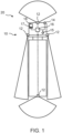
- Figure 1 shows a vehicle 20 according to an embodiment of the disclosure.
- the vehicle 20 is depicted as a truck in Figure 1 .
- the vehicle 20 may be, however, any type of vehicle, like, for example, a car, a bus, a construction machine, an agricultural machine or the like.
- the vehicle 20 comprises at least one imaging device 12, a condition device 14, and an image data processing device 16.
- the afore-mentioned components may be connected to each other.
- the image data processing device 16 can be connected to the at least one imaging device 12 and the condition device 14, e.g. by respective signal connections (dotted lines).
- Each of the respective signal connections can be a cable connection and/or a wireless connection.
- the at least one imaging device 12, the condition device 14, and the image data processing device 16 may form a vision system 10 and/or may be part of a vision system 10 (e.g. a mirror replacement system) of the vehicle 20.
- the vehicle 20 may comprise a vision system 10, including the at least one imaging device 12, the condition device 14, and the image data processing device 16.
- the at least one imaging device 12 may be configured to capture (e.g. real-time) image data.
- the at least one imaging device 12 can comprise one camera or several cameras.
- the one camera or several cameras may be mounted in or on a camera arm, which preferably extends laterally-outwardly from the vehicle body (e.g. laterally-outwardly from a cab of the vehicle).
- the at least one imaging device 12 may include at least one image sensor (e.g. a complementary metal-oxide-semiconductor (CMOS) image sensor and/or a charged-couple device (CCD) image sensor).
- CMOS complementary metal-oxide-semiconductor
- CCD charged-couple device
- the at least one imaging device 12 may include one or more optical elements (e.g. a lens, a mechanical shutter, an electrical shutter, and/or an aperture).
- the at least one imaging device 12 may be configured for detecting optical information of the vehicle's surroundings.
- the at least one imaging device 12 may be configured to capture forward image data (of the vehicle's surroundings) ahead of the vehicle 20, to capture lateral image data (of the vehicle's surroundings) besides (e.g. left and/or right besides) the vehicle 20, and/or to capture rearward image data (of the vehicle's surroundings) behind the vehicle 20.
- the at least one imaging device 12 may be configured to capture a rear facing side view of the vehicle's surroundings (along the vehicle 20).
- This rear facing side view may at (e.g., due to an arrangement of the at least one imaging device 12 in front of the windshield of the vehicle 20) least in parts also include portions of the vehicle's surroundings lying (directly) in front and/or laterally in front of the vehicle.
- the at least one imaging device 12 may be configured for capturing, e.g. according to the Directive 2003/97/EC and 2007/38/EC legally required, fields of views of the vehicle's surroundings.
- the at least one imaging device 12 may be configured for capturing a class II view, which may include a distant rear view laterally along the vehicle 20.
- the class II view may correspond to a field of view conventionally captured by a main exterior rear mirror of the vehicle 20.
- the at least one imaging device 12 may be configured for capturing a class IV view, which may include a (rearward-facing) wide angle view of the lateral surrounding of the vehicle 20.
- a class IV view may cover a shorter but wider lateral part of the vehicle's surroundings.
- the class IV view may correspond to a field of view conventionally captured by a wide-angle exterior mirror of the vehicle 20.
- the at least one imaging device 12 may be configured for capturing a class V view, which may include a close-proximity view of a lateral region besides (and possibly partly in front of) a cab of the vehicle 20, in particular at a lateral region besides the passenger's side of the vehicle 20 and/or cab of the vehicle 20.
- the lateral region may start at the leading edge of the vehicle 20.
- the class IV view may correspond to a field of view conventionally captured by a ramp mirror and/or side area safety mirror of the vehicle 20.
- the (received) image data may comprise class II view image data, class IV view image data, and/or class V image data.
- the (received) image data may also comprise class I view image and/or class III view image data.
- the at least one imaging device 12 may comprise several (e.g. four) imaging devices 12.
- the several imaging devices 12 may be arranged distributed at the vehicle 20.
- the several imaging devices 12 may be orientated differently and/or may have different fields of observation, respectively.
- the at least one imaging device 12 may comprise a rear view camera, a front view camera, and/or a lateral view camera.
- the at least one imaging device 12 or the several imaging devices 12 may form part of a mirror replacement system of the vehicle 20 (e.g. replacing an external rear-view mirror) and/or a birdview system of the vehicle 20.
- the condition device 14 may be configured to generate and/or output a condition-signal.
- the condition-signal may indicate a day-time condition or a night-time condition.
- the condition-signal may also indicate a light condition of the vehicle's surroundings.
- the condition-signal may have a first condition-signal value, when a brightness of the vehicle's surroundings is above a predefined value, and a second, when the brightness of the vehicle's surroundings is below this predefined value.
- the condition device 14 may comprise a brightness and/or light sensor.
- the condition device 14 may also comprise a clock, a timer and/or an interface configured to receive an external input indicating a day-time condition and/or night-time condition.
- the image data processing device 16 may be configured to receive input from the at least one imaging device 12 and the condition device 14.
- the image data processing device 16 may be configured to receive the captured image data from the at least one imaging device 12 and the generated condition-signal from the condition device 14.
- the image data processing device 16 may include a memory and/or at least one processor (e.g., an Image Signal Processor - ISP) for processing images and/or image data.
- the memory can be configured to store instructions, which can be executed by the at least one processor.
- the image data processing device 16 may be configured to process the received image data.
- the image data processing device 16 may be configured to alter the received image data (e.g. a quality and/or a key performance indicator of received image data) through image-processing.
- the mage data processing device 16 may be configured to adjust or alter a contrast, a digital gain, a noise filtering, a white balance, a luminance, a brightness, and/or a sharpness of the received image data.
- the image data processing device 16 may be configured to process the received image data dependent on the received condition-signal.
- the image data processing device 16 may be configured to process the received image data differently depending on the received condition-signal, which will be described on more detail in the context of Figures 2 , 3 and 4 .
- the processing may differ depending on whether the received condition-signal indicates the day-time condition or the night-time condition.
- the received condition-signal may trigger a day mode or a night mode of the image data processing device 16 for processing the received image data.
- Dependent on the condition-signal and/or the respective mode (day or night mode) image processing settings used for processing the received image data may vary.
- the image data processing device 16 may be configured to adjust the contrast, digital gain, noise filtering, white balance, luminance, brightness, and/or sharpness of the received image data dependent on the received condition-signal and/or mode.
- the e image data processing device 16 may be configured to optimize the image quality respectively for day-time condition and/or night-time conditions.
- the image data processing device 16 may be configured to increase the contrast and/or to decrease the brightness of the received image data when the received condition-signal indicates the night-time condition.
- the image data processing device 16 may be configured to output a control-signal to the at least one imaging device 12.
- the control-signal may cause the at least one imaging device 12 to alter and/or adjust at least one image capture setting of the at least one imaging device 12.
- the term image capture setting may, for example, refer to (hardware or software) settings of the at least one imaging device 12, which determine the way the (e.g. raw) image data is captured by the at least one imaging device 12.
- the at least one image capture setting may comprise a frame rate, a (analogue) gain, a black level, an exposure time, and/or exposure threshold of the at least one imaging device 12.
- the frame rate may define a number of frames per second that the at least one imaging device 12 will attempt to deliver.
- the black level may define a level of brightness, which corresponds to the darkest value of the at least one imaging device 12. By adjusting the black level, a possible dark current may be compensated.
- the exposure time may define a length of time that the at least one imaging device 12 collects photons for each frame.
- the exposure threshold may define a level, where a saturation of the at least one imaging device 12 is reached.
- the at least one image capture setting may also comprise a focus and/or aperture of the at least one imaging device 12.
- the image data processing device 16 may be configured to output the control-signal to the at least one imaging device 12 dependent on the received signal.
- the image data processing device 16 may be configured to output the control-signal differently depending on the received condition-signal, which will be described in more detail in the context of Figures 2 , 3 and 4 .
- the outputting may differ depending on whether the received condition-signal indicates the day-time condition or the night-time condition.
- the situation detection device 15 may be configured to generate and/or output a situation-signal.
- the situation-signal may indicate a (e.g. current) speed, a gear selection and/or an operating state of the vehicle 20.
- the situation detection device 15 may be connected to respective controllers and/or sensor devices of the vehicle 20, e.g. a speed sensor, a gear position sensor, and/or a steering angle sensor.
- the situation detection device 15 may be configured to receive positioning data from a (e.g. GPS) positioning system of the vehicle.
- the situation detection device 15 may be configured to generate and/or output the situation-signal based on the information received from the controllers, sensor devices, and/or positioning system.
- the situation-signal generated by the situation detection device 15 may have a first situation-signal value indicating a reverse driving of the vehicle 20, e.g. when a reverse gear of the vehicle 20 is engaged.
- the situation-signal may have a second situation-signal value indicating a motorway driving of the vehicle 20, e.g. when the speed of the vehicle 20 exceeds 60 km/h or one 100 km/h.
- the situation-signal may have a third situation-signal value indicating a manoeuvring of the vehicle 20, e.g. when the speed of the vehicle 20 is below 25 km/h and/or (strong) steering movements are present.
- the image data processing device 16 may be further configured to process the received image data dependent on the received situation-signal.
- the image data processing device 16 may be configured to process the received image data differently depending on the received situation-signal.
- the received situation-signal may trigger different modes of image data processing of the image data processing device 16 for processing the received image data.
- the night mode may (automatically) adapt to different situations and/or operating states of the vehicle 20 (during night), dependent on the situation-signal.
- the image processing settings may change (automatically) for different driving speeds and directions (forward/reverse).
- different predefined image data processing modes may be stored and/or specified within the image data processing device 16.
- the predefined image data processing modes may, for example, include at least three, preferably at least four, predefined image data processing modes.
- the different predefined image data processing modes may define different image processing settings used for processing the received image data.
- the image data processing device 16 may, thereby, be configured to select an image data processing mode from, the predefined possible image data processing modes dependent on the received situation-signal. This may be achieved via predefined rules or allocation tables, which assign different values of the situation-signal to a corresponding image data processing mode.
- an optimisation method e.g. a gradient-based Newton method and/or genetic optimisation
- the image data processing device 16 may be configured to process the received image data in accordance with the selected image data processing mode. For example, the way the received image data are processed and/or the used image processing settings may differ depending on the selected image data processing mode.
- the predefined image data processing modes may comprise, for example, a default mode, a reverse driving mode, a motorway driving mode, and/or a manoeuvring mode.
- the default mode may for example be an inner-city driving mode.
- the default mode may be enabled by default unless the situation-signal indicates another operating state of the vehicle, e.g. reverse driving, motorway driving, and/or manoeuvring.
- the default mode may be selected by the image data processing device 16, when the received situation-signal indicates an inner-city driving of the vehicle.
- the situation-signal may have a fourth situation-signal value indicating an inner-city driving of the vehicle, e.g. when the speed of the vehicle 20 is between 25 km/h and 60 km/h.
- the image data processing device 16 may be configured to generate a combined view of the received image data (in a single image). For this, different field of views contained in the received image data may be merged.
- the class II, IV and V view image data may be combined and/or adjoined to each in a single image.
- the image data or processed image data may comprise (e.g. perspective) distortions and/or deformations.
- the reverse driving mode may be selected by the image data processing device 16, when the received situation-signal indicates reverse driving of the vehicle 20.
- the image data processing device 16 may be configured to generate a wide-angle view of the received image data.
- the received image data may comprise rearward image data (e.g. captured by a rear camera). Particularly preferred, only rearward image data is processed during the processing step in the reverse driving mode.
- the image data processing device 16 may further be configured to increase a contrast, brightness and/or digital gain of the received image data compared to a contrast, brightness and/or digital gain in the default mode.
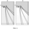
- the motorway driving mode which is illustrated in Figure 3 and 4 , may be selected by the image data processing device 16, when the received situation-signal indicates motorway driving of the vehicle 20.
- the image data processing device 16 may be configured to generate a zoom view of the received image data.
- the term zoom view may, for example, refer to a view focussing on a specific portion of the captured image data, e.g. relating to a specific portion of the external environment of the vehicle 20.
- the zoom view may include an enlarged and/or magnified representation of parts of the captured image data.
- the class V view may be decreased (e.g. reduced) compared to the default mode and /or the manoeuvring mode.
- the received image data may be processed such that the information on the front and the lateral vehicle's surroundings is minimized and the information on the rear vehicle's surroundings is maximized.
- the image data processing device 16 may further be configured to decrease a contrast, brightness and/or digital gain of the received image data compared to a contrast, brightness and/or digital gain in the default mode.
- the manoeuvring mode may be selected by the image data processing device 16, when the received situation-signal indicates a manoeuvring of the vehicle 20.
- the image data processing device 16 may be configured to generate a wide-angle view of the received image data.
- the class V view may be increased (e.g. magnified) compared to the default mode and/or motorway driving mode.
- the class IV view and/or class II view may be decreased (e.g. reduced) compared to the default mode and/or motorway driving mode.
- the image data processing device 16 may further be configured to increase a contrast, brightness and/or digital gain of the received image data compared to a contrast, brightness and/or digital gain in the default mode.
- the coupling may be asymmetrical, i.e. the contrast may be increased much stronger (for manoeuvring) than it can be decreased (for motorway driving and/or long-distance drives).
- the vehicle 20 may comprise a display device 18.
- the display device 18 may be connected with the image data processing device 16, e.g. by a respective signal connection (dotted line).
- the display device 18 may be part of the vision system 10 of the vehicle 20.
- the vision system 10 may further comprise the display device 18.
- the display device 18 may be configured to display the processed image data (e.g. in real-time, i.e. the situation displayed on the display device 18 preferably corresponds to the actual situation outside the vehicle 20).
- the display device 18 may be configured to receive the processed image data from the image data processing device 16.
- the display device 18 may comprise a display (e.g. a LCD display) and/or monitor.
- the display and/or monitor may be a touch sensitive (e.g. configured as a touch screen).
- the processed image data may be displayed on a monitor and/or display of the display device 18.
- the display device 18 may be arranged at a dashboard of the vehicle 20. Alternatively, the display device 18 may be arranged at an A-pillar of the vehicle 20.
- the display device 18 and/or the whole vision system 10 may be part of a mirror replacement system of the vehicle 20. Thus, the display device 18 may be configured to display an area of the vehicle's surroundings usually visible via a (absent) mirror of the vehicle 20.
- the display device 18 may be permanently active during operation of the vehicle 20.
- the display device 18 and/or the whole vision system 10 may be operable to display a surround view (or bird's eye view) of the vehicle's surroundings.
- the display device 18 may comprise a dimmer to adjust a brightness of the display and/or the monitor of the display device 18.
- the dimmer may be formed as a knob and/or button at the display device 18.
- the dimmer may, however, also be formed as a (virtual) key displayed on the (touch sensitive) display and/or monitor.
- the display device 18 may be configured to generate and/or output a display-brightness-signal.
- the display-brightness-signal thereby, may indicate a (current) brightness of the display and/or monitor of the display device 18.
- the display-brightness-signal may be proportional to a displacement or setting of the dimmer.
- the display-brightness-signal may, in particular, indicate a brightness of a backlight of a display and/or monitor of the display device 18.
- the image data processing device 16 may be configured to process the received image data dependent on the received display-brightness-signal.
- the image data processing device 16 may be configured to process the received image data differently depending on the received display-brightness-signal.
- the image processing settings may be coupled with the dimmer, i.e. the manual brightness adjustment of the display.
- the image data processing device 16 may be configured to increase a contrast of the received image data, when the display-brightness-signal indicates an increase of the brightness of the display and/or to decrease a contrast of the received image data, when the display-brightness-signal indicates a decrease of the brightness of the display.
- the display-brightness-signal may be coupled asymmetrically to the image processing settings.
- the display device 18 and/or the vehicle 20 may comprise a control device 17.
- the control device 17 may include one or more of a touchscreen, a button, or a switch.
- the control device 17 may be arranged at and/or integrated in the display device 18.
- the control device 17 may be part of the vision system 10 of the vehicle 20.
- the control device 17 may be configured to generate and/or output a user-request signal, e.g. based on inputs and/or actuations of the control device 17.
- the user-request signal may indicate a command and/or request of a user, e.g. associated with the (post-)processing of the received image data.
- the user-request signal may indicate a selection and/or adjustment of an image data processing mode; a change of image processing settings; and/or a change and/or selection of a view (e.g. a zoom or wide-angle view).
- the image data processing device 16 may be configured to process the received image data dependent on the received user-request signal.
- the processing of the image data processing device 16 may be actively altered and/or adjusted by a user.
- the image data processing device 16 may be configured to adjust image processing settings dependent on the received user-request signal.
- the driver can thus preferably control the extent of the image processing settings manually.
- the image processing settings of the night mode may be adjusted manually by the driver.
- the image data processing device 16 may be configured to adjust the selected image data processing mode dependent on the received user-request signal and/or to select another image data processing mode dependent on the received user-request signal.
- the user may (manually) request a change of the reverse driving mode to the manoeuvring mode, e.g. by performing a corresponding control action at the control device 17 (e.g. by pressing a manoeuvring mode button of the control device 17).
- the control device 17 may then generate and output a respective user-request signal, indicating the afore-mentioned change of the image data processing mode, and the image data processing device 16 may be configured to change the respective image data processing mode based on the received user-request signal.
- the image data processing device 16 may be configured to adjust the contrast, digital gain, noise filtering, white balance, luminance, brightness, and/or sharpness of the received image data dependent on the received user-request signal.
- the user may (manually) request a change of the contrast of the (displayed) image data, e.g. by performing a corresponding control action at the control device 17 (e.g. by operating a contrast key of the control device 17).
- the control device 17 may then generate and output a respective user-request signal, indicating the afore-mentioned change of the contrast, and the image data processing device 16 may be configured to change the contrast of the received image data based on the received user-request signal.
- the image data processing device 16 may be configured to adjust a section of the received image data to be displayed dependent on the received user-request signal.
- the image data processing device 16 may be configured to adjust an image range and/or view generated from the received image data to be displayed dependent on the received user-request signal.
- the image data processing device 16 may be configured to generate a zoom view or wide-angle view of the received image data dependent on the received user-request signal.
- the user may (manually) request a change of the view of a currently (displayed) zoom view to a wide-angle view, e.g. by performing a corresponding control action at the control device 17 (e.g.
- control device 17 may then generate a respective user-request signal, indicating the afore-mentioned view change, and the image data processing device 16 may be configured to generate a wide-angle view of the received image data based on the received user-request signal.
- Figure 4 shows schematic representations of processed image data in the default, manoeuvring, and motor driving mode, wherein the processed image data comprises different field of views.
- the processed image data (and the received image data) comprises image data related to a class II view, a class IV view, and a class V view of the vehicle's surroundings according to the Directive 2003/97/EC and 2007/38/EC.
- the different field of views may be merged to a combined view, wherein the relative portions of the different field of views in the combined view may vary according to the respective image processing mode. For example, in the manoeuvring mode, the portion of the class V view may be increased compared to the default mode.
- the (identical) class V view or class V view image data may be displayed larger on the display device 18 as in the default mode.
- the portion of the class IV view and class II view may be decreased compared to the default mode.
- the class II and class IV views may be displayed smaller on the display device 18 compared to the situation in the default mode.
- the portion of the class V view may be decreased (e.g. reduced) compared to the default mode. Consequently, here, the class V view or class V view image data may be displayed smaller on the display device 18 as in the default mode.
Landscapes
- Engineering & Computer Science (AREA)
- Multimedia (AREA)
- Signal Processing (AREA)
- Mechanical Engineering (AREA)
- Chemical & Material Sciences (AREA)
- Combustion & Propulsion (AREA)
- Transportation (AREA)
- Closed-Circuit Television Systems (AREA)
- Studio Devices (AREA)
Applications Claiming Priority (1)
| Application Number | Priority Date | Filing Date | Title |
|---|---|---|---|
| DE102023127318.3A DE102023127318B4 (de) | 2023-10-06 | 2023-10-06 | Aktivierung und Optimierung eines Nachtmodus in Kamera-Monitor-Anwendungen |
Publications (1)
| Publication Number | Publication Date |
|---|---|
| EP4534351A1 true EP4534351A1 (fr) | 2025-04-09 |
Family
ID=92932576
Family Applications (1)
| Application Number | Title | Priority Date | Filing Date |
|---|---|---|---|
| EP24203467.6A Pending EP4534351A1 (fr) | 2023-10-06 | 2024-09-30 | Activation et optimisation d'un mode de nuit dans des applications de surveillance de caméra |
Country Status (4)
| Country | Link |
|---|---|
| US (1) | US20250119653A1 (fr) |
| EP (1) | EP4534351A1 (fr) |
| CN (1) | CN119788971A (fr) |
| DE (1) | DE102023127318B4 (fr) |
Citations (3)
| Publication number | Priority date | Publication date | Assignee | Title |
|---|---|---|---|---|
| US20190034752A1 (en) * | 2017-07-25 | 2019-01-31 | Mekra Lang Gmbh & Co. Kg | Indirect View System For a Vehicle |
| DE102018207388A1 (de) * | 2018-05-14 | 2019-11-14 | Continental Automotive Gmbh | Verfahren und Vorrichtung zur Erzeugung eines Anzeigebildes in einem Kraftfahrzeug |
| US20230156309A1 (en) * | 2021-11-18 | 2023-05-18 | Canon Kabushiki Kaisha | Image processing apparatus, image processing method, and image capturing apparatus |
Family Cites Families (7)
| Publication number | Priority date | Publication date | Assignee | Title |
|---|---|---|---|---|
| US8340870B2 (en) * | 2008-09-16 | 2012-12-25 | Honda Motor Co., Ltd. | Vehicle maneuver assistance device |
| TWM353849U (en) * | 2008-09-17 | 2009-04-01 | Jyh-Chiang Liou | Integrated driving assistance apparatus |
| DE102011083786A1 (de) * | 2011-09-29 | 2013-04-04 | Robert Bosch Gmbh | Fahrzeug-Kamerasystem mit automatischem Farbabgleich |
| KR101816423B1 (ko) * | 2016-07-12 | 2018-01-08 | 현대자동차주식회사 | 사이드 미러 대체 디스플레이 장치 및 이의 출력 밝기 제어 방법 |
| EP3880519B1 (fr) * | 2018-11-12 | 2024-04-03 | Volvo Truck Corporation | Dispositif de garde latérale, ensemble et véhicule comprenant un tel dispositif de garde latérale et procédé de manoeuvre d'un tel véhicule |
| US11153950B2 (en) * | 2019-02-14 | 2021-10-19 | Orlaco Products B.V. | Replacement mirror system with IR LED overheating management |
| KR102170191B1 (ko) * | 2019-09-26 | 2020-10-27 | 박호준 | 듀얼 카메라를 이용한 차량 주행 보조 장치 |
-
2023
- 2023-10-06 DE DE102023127318.3A patent/DE102023127318B4/de active Active
-
2024
- 2024-09-30 EP EP24203467.6A patent/EP4534351A1/fr active Pending
- 2024-10-04 US US18/906,883 patent/US20250119653A1/en active Pending
- 2024-10-08 CN CN202411390840.3A patent/CN119788971A/zh active Pending
Patent Citations (3)
| Publication number | Priority date | Publication date | Assignee | Title |
|---|---|---|---|---|
| US20190034752A1 (en) * | 2017-07-25 | 2019-01-31 | Mekra Lang Gmbh & Co. Kg | Indirect View System For a Vehicle |
| DE102018207388A1 (de) * | 2018-05-14 | 2019-11-14 | Continental Automotive Gmbh | Verfahren und Vorrichtung zur Erzeugung eines Anzeigebildes in einem Kraftfahrzeug |
| US20230156309A1 (en) * | 2021-11-18 | 2023-05-18 | Canon Kabushiki Kaisha | Image processing apparatus, image processing method, and image capturing apparatus |
Also Published As
| Publication number | Publication date |
|---|---|
| DE102023127318A1 (de) | 2025-04-10 |
| US20250119653A1 (en) | 2025-04-10 |
| DE102023127318B4 (de) | 2025-04-30 |
| CN119788971A (zh) | 2025-04-08 |
Similar Documents
| Publication | Publication Date | Title |
|---|---|---|
| US9123179B2 (en) | Surrounding image display system and surrounding image display method for vehicle | |
| US20120002052A1 (en) | Obstacle detection apparatus, obstacle detection system having same, and obstacle detection method | |
| US20190092239A1 (en) | Image-pickup apparatus, image-pickup display method, and image-pickup display program | |
| EP2590397A2 (fr) | Égalisation d'image automatique pour systèmes de caméras vidéos à visualisation panoramique | |
| JP2004058828A (ja) | 車両前方表示システム | |
| JP2019125920A (ja) | モニター表示システム及びその表示方法 | |
| JP2016523204A (ja) | ミラー代替手段、並びに、車両 | |
| WO2017195684A1 (fr) | Dispositif de reconnaissance visuelle pour un véhicule | |
| EP3076655B1 (fr) | Dispositif de modification de paramétrages de formation d'image, système de formation d'image, et procédé de modification de paramétrages de formation d'image | |
| WO2011000392A1 (fr) | Procédé et système de caméra permettant d'améliorer le contraste d'une image de caméra | |
| US20250319818A1 (en) | Method for the Harmonized Display of Camera Images in a Motor Vehicle, and Correspondingly Designed Motor Vehicle | |
| JP7051667B2 (ja) | 車載装置 | |
| EP3674139A1 (fr) | Système de rétroviseur électronique | |
| EP4534351A1 (fr) | Activation et optimisation d'un mode de nuit dans des applications de surveillance de caméra | |
| CN114097216B (zh) | 图像处理装置 | |
| EP4181520A1 (fr) | Commande de del ir automatique pour système de rétroviseur caméra | |
| JP2017028349A (ja) | 映像処理装置、運転支援表示システム、及び映像処理方法 | |
| CN221090665U (zh) | 车载防眩目后视系统及车辆 | |
| JP2005033709A (ja) | 車両用周辺監視装置 | |
| JP3027979B2 (ja) | 車載カメラ用オプトエレクトロニックフィルタ | |
| JP7009334B2 (ja) | 画像表示装置、画像表示システム | |
| DE102023005536B4 (de) | Aktivierung und Optimierung eines Nachtmodus in Kamera-Monitor-Anwendungen | |
| DE102023005537B4 (de) | Aktivierung und Optimierung eines Nachtmodus in Kamera-Monitor-Anwendungen | |
| KR200484997Y1 (ko) | 내시경 응용한 차량 사이드 미러 장치 | |
| EP4339027B1 (fr) | Dispositif d'affichage d'image côté arrière de véhicule |
Legal Events
| Date | Code | Title | Description |
|---|---|---|---|
| PUAI | Public reference made under article 153(3) epc to a published international application that has entered the european phase |
Free format text: ORIGINAL CODE: 0009012 |
|
| STAA | Information on the status of an ep patent application or granted ep patent |
Free format text: STATUS: THE APPLICATION HAS BEEN PUBLISHED |
|
| AK | Designated contracting states |
Kind code of ref document: A1 Designated state(s): AL AT BE BG CH CY CZ DE DK EE ES FI FR GB GR HR HU IE IS IT LI LT LU LV MC ME MK MT NL NO PL PT RO RS SE SI SK SM TR |
|
| STAA | Information on the status of an ep patent application or granted ep patent |
Free format text: STATUS: REQUEST FOR EXAMINATION WAS MADE |
|
| 17P | Request for examination filed |
Effective date: 20250925 |
|
| RAP3 | Party data changed (applicant data changed or rights of an application transferred) |
Owner name: MAN TRUCK & BUS SE Owner name: MOTHERSON INNOVATIONS COMPANY LIMITED |