EP4534432A1 - Découpe, partie extérieure, conteneur d'emballage combiné avec un conteneur et une partie extérieure, procédé de fabrication d'un conteneur d'emballage combiné, procédé d'ouverture d'un contenaneur d'emballage combiné - Google Patents
Découpe, partie extérieure, conteneur d'emballage combiné avec un conteneur et une partie extérieure, procédé de fabrication d'un conteneur d'emballage combiné, procédé d'ouverture d'un contenaneur d'emballage combiné Download PDFInfo
- Publication number
- EP4534432A1 EP4534432A1 EP24199763.4A EP24199763A EP4534432A1 EP 4534432 A1 EP4534432 A1 EP 4534432A1 EP 24199763 A EP24199763 A EP 24199763A EP 4534432 A1 EP4534432 A1 EP 4534432A1
- Authority
- EP
- European Patent Office
- Prior art keywords
- outer part
- container
- face
- blank
- region
- Prior art date
- Legal status (The legal status is an assumption and is not a legal conclusion. Google has not performed a legal analysis and makes no representation as to the accuracy of the status listed.)
- Pending
Links
Images


Classifications
-
- B—PERFORMING OPERATIONS; TRANSPORTING
- B65—CONVEYING; PACKING; STORING; HANDLING THIN OR FILAMENTARY MATERIAL
- B65D—CONTAINERS FOR STORAGE OR TRANSPORT OF ARTICLES OR MATERIALS, e.g. BAGS, BARRELS, BOTTLES, BOXES, CANS, CARTONS, CRATES, DRUMS, JARS, TANKS, HOPPERS, FORWARDING CONTAINERS; ACCESSORIES, CLOSURES, OR FITTINGS THEREFOR; PACKAGING ELEMENTS; PACKAGES
- B65D25/00—Details of other kinds or types of rigid or semi-rigid containers
- B65D25/34—Coverings or external coatings
- B65D25/36—Coverings or external coatings formed by applying sheet material
-
- B—PERFORMING OPERATIONS; TRANSPORTING
- B65—CONVEYING; PACKING; STORING; HANDLING THIN OR FILAMENTARY MATERIAL
- B65D—CONTAINERS FOR STORAGE OR TRANSPORT OF ARTICLES OR MATERIALS, e.g. BAGS, BARRELS, BOTTLES, BOXES, CANS, CARTONS, CRATES, DRUMS, JARS, TANKS, HOPPERS, FORWARDING CONTAINERS; ACCESSORIES, CLOSURES, OR FITTINGS THEREFOR; PACKAGING ELEMENTS; PACKAGES
- B65D1/00—Rigid or semi-rigid containers having bodies formed in one piece, e.g. by casting metallic material, by moulding plastics, by blowing vitreous material, by throwing ceramic material, by moulding pulped fibrous material or by deep-drawing operations performed on sheet material
- B65D1/22—Boxes or like containers with side walls of substantial depth for enclosing contents
- B65D1/26—Thin-walled containers, e.g. formed by deep-drawing operations
-
- B—PERFORMING OPERATIONS; TRANSPORTING
- B65—CONVEYING; PACKING; STORING; HANDLING THIN OR FILAMENTARY MATERIAL
- B65D—CONTAINERS FOR STORAGE OR TRANSPORT OF ARTICLES OR MATERIALS, e.g. BAGS, BARRELS, BOTTLES, BOXES, CANS, CARTONS, CRATES, DRUMS, JARS, TANKS, HOPPERS, FORWARDING CONTAINERS; ACCESSORIES, CLOSURES, OR FITTINGS THEREFOR; PACKAGING ELEMENTS; PACKAGES
- B65D1/00—Rigid or semi-rigid containers having bodies formed in one piece, e.g. by casting metallic material, by moulding plastics, by blowing vitreous material, by throwing ceramic material, by moulding pulped fibrous material or by deep-drawing operations performed on sheet material
- B65D1/22—Boxes or like containers with side walls of substantial depth for enclosing contents
- B65D1/26—Thin-walled containers, e.g. formed by deep-drawing operations
- B65D1/265—Drinking cups
-
- B—PERFORMING OPERATIONS; TRANSPORTING
- B65—CONVEYING; PACKING; STORING; HANDLING THIN OR FILAMENTARY MATERIAL
- B65D—CONTAINERS FOR STORAGE OR TRANSPORT OF ARTICLES OR MATERIALS, e.g. BAGS, BARRELS, BOTTLES, BOXES, CANS, CARTONS, CRATES, DRUMS, JARS, TANKS, HOPPERS, FORWARDING CONTAINERS; ACCESSORIES, CLOSURES, OR FITTINGS THEREFOR; PACKAGING ELEMENTS; PACKAGES
- B65D25/00—Details of other kinds or types of rigid or semi-rigid containers
- B65D25/14—Linings or internal coatings
-
- B—PERFORMING OPERATIONS; TRANSPORTING
- B65—CONVEYING; PACKING; STORING; HANDLING THIN OR FILAMENTARY MATERIAL
- B65D—CONTAINERS FOR STORAGE OR TRANSPORT OF ARTICLES OR MATERIALS, e.g. BAGS, BARRELS, BOTTLES, BOXES, CANS, CARTONS, CRATES, DRUMS, JARS, TANKS, HOPPERS, FORWARDING CONTAINERS; ACCESSORIES, CLOSURES, OR FITTINGS THEREFOR; PACKAGING ELEMENTS; PACKAGES
- B65D2565/00—Wrappers or flexible covers; Packaging materials of special type or form
- B65D2565/38—Packaging materials of special type or form
- B65D2565/381—Details of packaging materials of special type or form
- B65D2565/385—Details of packaging materials of special type or form especially suited for or with means facilitating recycling
Definitions
- the invention relates to a blank, a sleeve-shaped outer part formed from a blank for encasing a container, in particular a cup-shaped container, and a combination packaging container formed from a container and an outer part.
- the invention further relates to a method for producing a combination packaging container, and a method for opening a combination packaging container.
- Recycling should enable the pure separation of different materials to improve recycling quality.
- the pure separation of different materials should be made as simple as possible so that any human oversights or errors during the recycling process can be compensated for as much as possible.
- used products and product packaging should be processed into reusable products and product packaging in a simple and sustainable manner.
- the WO 2020/245148 A1 describes a sleeve-shaped outer part formed from a blank, wherein the blank is wound into a jacket and the end sections of which are connected to one another in an overlapping area.
- the sleeve-shaped outer part together with a cup-shaped inner container, forms a combination packaging container.
- a predetermined separation area comprises an actuating means with a detection section for separating separation sections located on both sides. In a combination packaging container designed in this way, the predetermined separation area is intended to be separated after use of the container, which is why separation of the components and subsequent recycling or reuse is not guaranteed.
- the object of the present invention was to overcome the disadvantages of the prior art and to provide a blank, an outer part and a combination packaging container in which the sleeve-shaped outer part can be easily removed from the container for recycling purposes and in which it is also ensured that a user carries out this separation, while at the same time aiming to improve the closability and durability of container closures, in particular of reusable containers.
- the term “container” encompasses a variety of conceivable shapes, configurations, and intended uses. It can be a cup-shaped container, but also a tub-shaped, bowl-shaped, or bottle-shaped container.
- the invention relates to a blank for an outer part for encasing a container, in particular a cup-shaped container, which has a container shell which has an open end and an end closed by a base, wherein the blank has a basic shape which is essentially in the form of a segment of a circular ring, wherein the blank has a first end section and a second end section, wherein the blank can be wound into a shell and the first end section and the second end section can be coupled to one another in an overlapping region, wherein the blank further has a first end face and a second end face and wherein the first end face and the second end face are spaced apart from one another, wherein the blank has a longitudinal extension in a direction starting from the first end face to the second end face.
- the blank is provided with a fold line and a fold region, wherein the fold line is formed concentrically with respect to a circle center of the circular ring-segment-shaped basic shape in a flat, i.e., unwound, state of the blank.
- the fold region viewed in the longitudinal direction, is arranged between the fold line and the second end face.
- the fold region is foldable along the fold line. Folding here refers in particular to crimping, flanging, or fan-shaped or fan-like folding.
- the blank according to the invention has the surprising advantage that the folding area and the folding line can be used to separate the blank and a container, in particular a cup-shaped container, wrapped with the blank. must be removed to allow access to the contents contained in the container. This ensures improved separation and recycling in a particularly simple and visually appealing way.
- the blank can form high-quality and attractive outer packaging for a container, whereby the blank can also serve as proof of tamper-evident evidence and is thus considered “tamper-evident.”
- the folded fold area contributes to the protection of a closure element, such as a sealing plate or a thin lid, thereby increasing its stability and durability, particularly with regard to accidental puncture.
- sealing areas or sealing edges are protected and thus subject to little or no stress. This further contributes to the longevity and improves the protection of the contents contained in the container, for example, pasty or liquid contents such as dairy products, but also powdered contents or bulk materials of any kind.
- the blank is particularly, but not exclusively, suitable for wrapping reusable containers, especially reusable plastic containers or plastic cups. After the required separation from the wrapped container for use, the blank can be recycled in a largely pure state, while the container itself can be reused.
- the blank can be a part cut from a sheet or a sheet-like element, for example, from paper, cardboard, or even a thin plastic sheet.
- Composite materials made of paper, cardboard, and/or plastic, or even with a thin metal layer, are also conceivable.
- Aluminum-containing foils are also conceivable.
- the invention also relates to an outer part for encasing a container, in particular a cup-shaped container, which has a container shell which has an open end and an end closed by a bottom, wherein the outer part is formed from a blank, in particular from a blank according to the claims, which blank has a substantially circular ring-segment-shaped basic shape, which blank has a first end section and a second end section, wherein the blank is formed into a shell is wound and the first end portion and the second end portion are coupled to one another in an overlap region, wherein the outer part further has a first end face and a second end face and the first end face and the second end face are spaced apart from one another, wherein the outer part has a longitudinal extension in a direction starting from the first end face to the second end face.
- the jacket of the outer part has a fold line and a fold region, or a crimp region, wherein the fold line is formed concentrically to the jacket of the outer part with respect to a longitudinal axis of the jacket of the outer part, and wherein the fold region, in the unfolded state and viewed in the longitudinal extent, is arranged between the fold line and the second end face, and wherein the fold region is foldable or crimpable along the fold line in the radial direction to the longitudinal axis of the jacket of the outer part, such that the open end can be at least partially covered or closed by the fold region.
- Folding here means, in particular, crimping, flanging, or fan-shaped or fan-like folding.
- the fold line and/or the fold area may already be pre-folded, pre-crimped or pre-flanged before the outer part is wrapped around a container, or the fold line and/or the fold area may only be folded, crimped or flanged after the outer part has been wrapped around a container.
- the outer part according to the invention offers the surprising advantage that, thanks to the folding area and the folding line, the outer part and a container, particularly a cup-shaped container, wrapped with the outer part must be separated from each other to allow access to a product contained in the container.
- the outer part can form a high-quality and attractive outer packaging for a container, whereby the outer part can also fulfill a function as proof of originality and is thus considered "tamper evident.”
- the folded folding area contributes to the protection of a closure element, for example, a sealing plate or a thin lid, thus increasing its stability and durability, particularly with regard to accidental puncture.
- a sealing plate or a similar closure element the sealing areas or sealing edges protected and thus subjected to little or no wear. This further contributes to its longevity and improves the protection of the contents of the container, such as dairy products.
- the outer part is particularly, but not exclusively, suitable for wrapping reusable containers, in particular reusable plastic containers or plastic cups or reusable metal containers or the like. After the separation from the wrapped container required for use, the outer part can be recycled in a largely pure state, while the container can be reused.
- the fold line or the folding area above it extends over a large part of the length or the entire length of the second end face. This has the advantage that a comparatively large area or even the entire peripheral area of the open end of the container can be covered and protected by the fold. It can also be the case that the fold line extends only over part of the length of the first end face, for example, excluding the edge zone at the end sections in the overlapping area.
- the height of the fold area between the fold line and the second end face can be comparatively small, so that the folded fold area can only cover part of the open end or a closure element. However, the height can also be so large that it can cover a large part of the open end or a closure element, or the entire open end or the entire closure element.
- the height of the fold area can also be constant, but can also vary along its length.
- the outer part may comprise a cellulose fiber-containing material or be formed from a cellulose fiber-containing material. This can increase recyclability and reusability.
- the outer part may also comprise plastics, composite materials, or the like.
- Cellulose fiber-containing materials with a metallized surface, or a metallized layer, and/or with a lacquered surface are also conceivable. This may, for example, improve foldability and/or allow the outer part to be used as a sealing plate.
- the outer part may comprise a Metal foil. This is especially true when the outer part serves both to enclose the container and as a closure element, particularly as a sealing plate, for sealing the open end of the container.
- Another advantageous feature is a design in which the folding area, when folded radially to the longitudinal axis, has a multitude of folds, i.e., it is crimped, flanged, or fan-folded multiple times. This can achieve a visually appealing result. Furthermore, the material of the blank is reinforced, or doubled, in the fold area, thus further contributing to increased stability and improved longevity.
- the folding area can be formed with a plurality of further folding lines, wherein the further folding lines are not arranged parallel to the longitudinal axis of the casing of the outer part in an unfolded state, and wherein the further folding lines promote the formation of the folds when folded radially to the longitudinal axis.
- This can promote particularly regular folding during folding or crimping. This further contributes to a visually appealing appearance and also facilitates folding.
- folds can also be more durable and therefore of higher quality because they are less likely to unfold spontaneously.
- the additional fold lines can be formed in the outer part before it is wrapped around a container.
- the additional fold lines can also be created by an assembly system, such as a crimping machine.
- the fold line and/or the other fold lines may be material weakening lines, in particular perforations or punchings. Grooves, ribs, or pressings are also conceivable. This can further facilitate the formation of folds and prevent or reduce spontaneous unfolding.
- a predetermined separation area is provided in the jacket of the outer part, in particular in the overlapping area or in the vicinity of the overlapping area, which predetermined separation area extends in a direction starting from the first end face to the second end face or starting from the first end face to the fold line.
- Separation zones are known to experts in many different forms.
- the term "outline" is also commonly used.
- a separation zone such as the one in the WO 2020/245148 A1 by the applicant of the same name.
- the overlapping area of the end sections of the outer part also serves as the intended separation area.
- the overlapping area can be formed, for example, as a detachable adhesive connection between the overlapping end sections.
- the fold line is circular in shape. This is the case, at least in the outer part before it has been wound into a jacket, or in the cut-out state.
- first end face and/or the second end face may be circularly arc-shaped, and/or for the first end face and/or the second end face to be wavy or sinusoidal.
- first and second end faces are advantageously arranged parallel or at least substantially parallel to one another. It has also proven advantageous for wavy or sinusoidal end faces to substantially follow a circular arc shape, or rather the basic circular ring-segment-shaped shape of the outer part. A certain concentricity of the design has proven to be expedient.
- the folding area may have a tab or be designed as a tab, which tab is grippable by a user for opening or separating the outer part from an inner cup.
- the tab may form a predetermined separation area or be designed as part of a predetermined separation area. It may also be the case that a tab is dimensioned such that, when folded, it can cover all or a large part of the open end or a closure element. It is also conceivable that Formation of two tabs which are opposite one another in the wound state and which, in their folded state, can be brought into engagement with one another or can be coupled or fixed to one another so that they form a closure element.
- the combination packaging container according to the invention with a folded or crimped folding area of the outer part brings with it the surprising advantage that the folding area and the folding line make it possible to separate the outer part and the container, which is wrapped with the outer part in particular in the form of a cup, from one another in order to allow access to the contents contained in the container. Improved separation and recycling can be ensured in a particularly simple and visually appealing way.
- the outer part can form high-quality and attractive outer packaging for a container, whereby the outer part can also serve as proof of tamper-evident and is thus considered “tamper-evident.”
- the folded fold area contributes to the protection of a closure element, such as a sealing plate or a thin lid, thereby increasing its stability and durability, particularly with regard to accidental puncture.
- a closure element such as a sealing plate or a thin lid
- the sealing areas or sealing edges are protected and thus subject to little or no stress. This further contributes to longevity and improves the protection of the contents contained in the container, for example, dairy products.
- the outer part is particularly, but not exclusively, suitable for wrapping reusable containers, especially reusable plastic containers or plastic cups. After the separation from the wrapped container required for use, the outer part can be recycled in a largely pure state, while the container itself can be reused. It is also conceivable, in principle, for the outer part to be fixed, in particular glued, to the casing in certain areas.
- This design allows the outer part to contribute to protecting the closure element and prevent unwanted premature detachment or damage to the closure element. Furthermore, it can also be useful if the folding of the folding area also prevents or limits radial movement of the outer part relative to the container.
- the closure element can be a film, for example a sealing plate or sealing film.
- the closure element can alternatively or additionally be designed as a lid, for example a screw lid or a hinged lid.
- a closure element designed as a striker lid or a bouncer lid is also conceivable.
- the open end can be designed with a sealing edge, a flange, a collar, a striker edge, a thread, etc. In any case, it can be expedient if a region of the open end projects radially beyond the container shell and also beyond the shell of the outer part, relative to the longitudinal axis or the cone axis.
- the closure element can be covered with the folded folding area in such a way that removal of the closure element from the open end is only possible after unfolding the folding area or after removing the outer part from the container.
- closure element it is also conceivable for the closure element to be connected to the casing of the outer part, and for the closure element to be designed in such a way that it can be removed simultaneously with the removal of the outer part from the container.
- This has the advantage of facilitating use because both the outer part and the closure element can be removed in a single operation.
- the outer part is designed with a folding area, this folding area or possibly an additional one on the folding area can be connected or glued to the closure element, in particular to a sealing film, so that the sealing film can be removed together with the folding area.
- This can also facilitate recycling. This is particularly true if the closure element and the outer part remain connected to one another even after removal, or if the closure element and the outer part are at least substantially made of materials that can be recycled together.
- the shell of the outer part may extend over a part of the container shell, preferably between one-quarter and two-thirds of the container shell.
- part of the container height may be covered by the outer part, with the part of the container shell facing the container bottom remaining uncovered by the outer part and thus remains visible to the observer.
- the outer shell may extend over part of the container shell when viewed longitudinally. As a result, part of the container's height is covered by the outer shell. This has the advantage of improving sustainability by saving material. Furthermore, the visual appearance is appealing and distinctive.
- the outer part's jacket may extend over the entire container shell, i.e., envelop the entire container shell.
- the outer part's jacket may also extend over the closed end or the container base, covering it completely or partially.
- the folds, flanges, or crimp areas may also be formed on the container base.
- the container it is conceivable for the container to be a reusable container, in particular a reusable container comprising a plastic material. This has the advantage of further improving the sustainability of the combination packaging container. Furthermore, it may also be advantageous if the plastic material is a recycled material, or at least partially made from a recycled material. However, it may also be the case that the container is a disposable container.
- the folding area may have a tab that can be grasped by a user to open or separate the outer part from an inner cup.
- the tab may form a separation area or be designed as part of a separation area.
- the container shell of the container and the shell of the outer part are each substantially frustoconical and arranged around a common conical axis, and that a first angle between the container shell of the container and the conical axis is equal to or smaller than a second angle between the shell of the outer part and the conical axis.
- the longitudinal axis and the cone axis may be identical or congruent.
- the open end and/or the closure element has a collar projecting beyond the container shell in the radial direction to the cone axis, i.e. at 90° to the cone axis when viewing the container, wherein a third angle is formed between the cone axis and an imaginary intersection line, which imaginary intersection line extends from an outermost point of the collar to the cone axis and intersects the first end face.
- the third angle is the same size or at least approximately the same size as the second angle.
- An outermost point of the collar is a point furthest away from the longitudinal axis or from the cone axis, viewed in the radial direction.
- the collar with a symmetrical design, to have several such outermost points, in particular a circumferential outermost circle, on which circle the outermost points lie. This has the advantage of enabling a good connection or coupling between the outer part and the container.
- the collar may be designed with a flange, a thread or a striking edge.
- Such folding can also be referred to as crimping.
- the method according to the invention for producing a combination packaging container offers the surprising advantage that—particularly when the method is carried out in the described sequence—a combination packaging container as described above and with the advantages described above can be produced efficiently.
- the still unfilled and unsealed container is first covered with the outer parts, with the folding areas still unfolded, so that several such combination containers can be stacked inside each other.
- individual containers can be picked up from the stack and filled, closed, in particular sealed, and folded in the folding area.
- the container could first be covered with the outer part, or the outer part could be attached to the container, and only then could the container be filled and sealed.
- the open end of the container must be designed in such a way that a closure can still be applied even with the outer part installed and the folding area not yet folded.
- Forming an outer part from the blank by wrapping the container can be done by wrapping it directly onto the container.
- the container can be placed on a winding mandrel.
- the outer part could be formed by axially sliding the outer part onto the container, with the first end facing the bottom and the second end facing the open end of the inner container.
- the forming of the outer part and the joining of the first end section and the second end section in the overlapping area could be performed in a separate process step, and the thus formed outer part could be pushed onto the inner container from below by axial displacement in a subsequent process step.
- the container may be fixed and/or positioned in the region of the bottom of the container by coupling a coupling element to an alignment means, in particular to a groove or to a raised portion, before being wrapped with the outer part or before the outer part is pushed on axially.
- the invention also relates to a method for opening a combination packaging container, in particular a combination packaging container according to one of the claims, with a container, in particular a cup-shaped container, wherein the container has a container jacket which has an open end, which open end is closed with a closure element, and which has an end closed with a base, and with an outer part, in particular with an outer part according to one of the claims, which outer part encloses the container, wherein the outer part is formed from a blank, in particular from a blank according to the claims.
- the blank has a substantially circular ring-segment-shaped basic shape and has a first end section and a second end section, wherein the blank is wound into a jacket and the first end section and the second end section are coupled to one another in an overlapping region, wherein the outer part further has a first end face and a second end face and the first end face and the second end face are spaced apart from one another, wherein the outer part has a longitudinal extension in a direction starting from the first end face to the second end face, and wherein the jacket of the outer part has a fold line and a fold region, wherein the fold line is concentric with respect to a longitudinal axis of the jacket of the outer part to the jacket of the outer part, and wherein the folding region is arranged between the folding line and the second end face, viewed in the longitudinal extension, and wherein the folding region is folded along the folding line in the radial direction to the longitudinal axis of the jacket of the outer part, so that the open end and/or a region of the closure element is partially or completely
- the separation of the outer part from the container by opening the intended separation area can be complete, partial, or even partial.
- the outer part or part of the outer part is separated in such a way that the closure element can be removed after removal.
- the inventive method for opening a combination packaging container offers the surprising advantage that the user is shown, or rather guaranteed, that they are performing the initial opening of the originally sealed container. Furthermore, the user is virtually forced to detach the outer part from the container, thus encouraging recycling, as they would otherwise have no access to the contents of the container. This contributes significantly to sustainability, especially when the opening or initial opening process is performed in the described order.
- a flat blank 13 is shown, wherein the blank 13 can be wound into a sleeve-shaped outer part 12 or into a jacket.
- the flat blank 13 has a substantially circular ring-segment-shaped basic shape, wherein the blank 13 has a first end section 14 and a second end section 15.
- the two end sections 14, 15 are preferably each aligned along an imaginary line to the circle center of the circular ring-segment-shaped basic shape.
- the blank 13 can be wound into a sheath.
- the first end section 14 and the second end section 15 can be coupled to one another in an overlap region 16.
- the end sections 14, 15 can be connected to one another in an overlap region 16 (illustrated in a simplified manner).
- the first end section 14 of the blank 13 ends with a first longitudinal edge 17, and the second end section 15, in turn, ends with a second longitudinal edge 18.
- the two longitudinal edges 17, 18 can preferably each be aligned along an imaginary line to the circle center of the circular ring segment-shaped basic shape.
- the blank 13 can have a longitudinal edge length 33 in the region of the first end section 14, in particular at the first longitudinal edge 17.
- the two longitudinal edges 17, 18 run approximately parallel to one another, with the overlap region 16 being formed therebetween with an overlap width, as viewed in the circumferential direction of the casing.
- the second end section 15 is folded over the first end section 14 on the outside. It goes without saying that an arrangement is also conceivable in which the first end section 14 is folded over the second end section 15 on the outside.
- the blank 13, or an outer part 12 formed from the blank 13, further comprises a first end face 19 and a second end face 20, wherein the first end face 19 and the second end face 20 are spaced apart from one another, wherein the blank 13 or the outer part 12 has a longitudinal extension 22 in a direction starting from the first end face 19 to the second end face 20.
- the end faces are preferably substantially concentric with respect to the circle center of the circular ring segment-shaped basic shape.
- the two end faces 19, 20, which are spaced apart from one another, define an overall height 21 of the shell when the outer part 12 is erected. In particular, if the shell of the outer part 12 is conical, the overall height 21, when viewed in axial section, corresponds geometrically to a height of the cone.
- the longitudinal extent 22 for a conical shell of the outer part 12 is geometrically the length of the shell line.
- a blank 13 that is essentially in the shape of a segment of a circular ring inevitably results in a conical shell.
- the maximum longitudinal extent 22 for a conical shell of the outer part 12 is generally greater than the overall height 21 of the shell.
- the previously described longitudinal axis 8 can also define the common longitudinal axis for the outer part 12, in particular when the outer part 12 is in its mounted position on the container 2.
- the overall height 21 of the shell is slightly lower than the container height 9 of the container 2 in the same spatial direction - namely in the direction of the longitudinal axis 8.
- the blank 13 has a fold line 23 and a fold region 24, wherein the fold line 23 - in an unwound or in a flat state - is concentric with respect to a circle center of the circular ring segment-shaped basic shape, and the fold region 24 is arranged between the fold line 23 and the second end face 20, viewed in the longitudinal extent 22, and can be folded along the fold line 23.
- the fold line 23 extends over a large part of the length 25 or the entire length 25 of the second end face 20. In the illustrated embodiment, the fold line 23 extends over the entire length 25 of the second end face 20.
- Fig. 1 a variant is outlined in which the fold line 23 does not extend over the entire length 25 of the second end face 20, but in which the second end face 20 is not formed with the fold area 24 in the area adjacent to the end sections 14, 15, or the fold line 23 ends at least on one side in the overlap area 16. This, of course, is representative of a multitude of conceivable designs.
- the outer part 12 may comprise a cellulose fiber-containing material or be formed from a cellulose fiber-containing material.
- the folding region 24, in its state folded in the radial direction to the longitudinal axis 8, in particular in a fan-shaped folded, flanged or crimped state, has a plurality of folds 26. This is particularly the case in the Fig. 3 and 4 shown.
- the folding area 24, as in the Fig. 1 shown, is formed with a plurality of further fold lines 27, wherein the further fold lines 27 in an unfolded state are not arranged parallel with respect to the longitudinal axis 8 of the casing of the outer part 12 and wherein the further fold lines 27 in their folded state in the radial direction to the longitudinal axis 8, in particular folded in a fan shape, flanged or crimped, promote the formation of the folds 26 or crimping.
- first end face 19 and/or the second end face 20 may be formed in the shape of a circular arc, and/or the first end face 19 and/or the second end face 20 may be formed in the shape of a wave or sinusoid. It may also be that the fold line 23 is formed in the shape of a circular arc.
- the first end face 19 and the second end face 20 may be formed as shown in the Fig. 1 It can also be that the first end face 19 is circularly arc-shaped and that the second end face 20 is wave-shaped or are formed in a sinusoidal curve. It goes without saying that this embodiment is merely exemplary of various conceivable shapes. In any case, the first end face 19 and the second end face 20 essentially follow a circular arc shape and are essentially concentric with respect to a circle center of the circular ring segment-shaped basic shape.
- FIG. 2 and 3 An embodiment of a combination packaging container 1 is shown as an example for a variety of possible different shapes, wherein the combination packaging containers 1 are in particular cup-shaped or bowl-shaped.
- the combination packaging container 1 is in the Fig. 2 and 3 shown partially sectioned through the longitudinal axis 8.
- the combination packaging container 1 comprises a container 2, in particular cup-shaped or bowl-shaped, with a base 3 and a container shell 4.
- the container 2 further has an open end 5 on its side facing away from the base 3. Furthermore, in the region of its open end 5, a flange 6 projecting outwards beyond the container shell 4 can be provided.
- the base 3 forms a closed end 7 for the container shell 4.
- the container 2 has a substantially conical or truncated cone-shaped basic shape.
- the combination packaging container 1 When viewing the combination packaging container 1 in the front view shown, the combination packaging container 1 has a total height 10, which extends from the base 3 up to the highest region of the second end face 20 of the outer part 12. The total height 10 is thus greater than the container height 9 and also greater than the overall height 21 of the outer part 12.
- the container 2 is preferably formed from a component produced in a deep-drawing process, which can be manufactured quickly and, above all, in a short cycle time.
- the deep-drawing process is sufficiently well known and will therefore not be discussed in detail.
- the deep-drawing process is particularly suitable for producing the container 2 from a layer of a formable material to be formed using a deep-drawing tool, with a sufficient wall thickness that ensures tightness during storage, use, and even disposal.
- This manufacturing process allows relatively thin walls of the inner container 2 to be manufactured.
- the container 2 can also be formed using other manufacturing methods, such as an injection molding process.
- a longitudinal axis 8 extends axially between the open end 5 and the end 7 closed by the base 3.
- This longitudinal axis 8 can also represent a central axis if the design is symmetrical.
- a closure element 29 for example, a sealing plate.
- the flange 6 forms a sealing flange.
- the container 2 In the axial direction and thus in the direction of the longitudinal axis 8, the container 2 has a container height 9 between its open end 5, in particular the flange 6, and the base 3, whereby the receiving volume of the container 2 is determined depending on the cross-sectional dimensions.
- the container height 9 in conjunction with the cross-sectional dimensions thus defines a receiving space of the container 2.
- the container shell 4 is understood to be that section of the container 2 which extends predominantly axially between the open end 5, in particular the flange 6, and the base 3.
- the container 2 with its container shell 4 is designed such that it tapers conically from the open end 5 toward the base 3, i.e., is essentially frustoconical.
- the longitudinal axis 8 corresponds to the cone axis 34.
- the combination packaging container 1 further comprises an outer part 12 which is sleeve-shaped or jacket-shaped and surrounds the container 2 in the region of its container jacket 4 at least in sections or regions.
- the sleeve-shaped outer part 12 is preferably formed from a cellulose material, such as cardboard, with sufficient strength with regard to the absorption and transmission of, in particular, axially acting compressive forces, and is wound from a flat blank 13 into a sleeve.
- the blank 13 is usually printed in its undeformed, flat position and, if necessary, provided with an additional coating.
- the material used for the blank 13 is usually a cellulose material, although this can also be cardboard or strong paper produced using a recycling process.
- the cardboard is additionally coated or sealed with a water-repellent material in the area of the cut edges. This is particularly advantageous when the combination packaging container 1 is exposed to increased moisture ingress. Coating the cardboard used for the outer part 12 with a water-repellent layer prevents the cardboard from swelling in a humid environment and ultimately detaching from the container shell 4 of the combination packaging container 1.
- the container 2 may preferably be a reusable container, which in particular is or comprises a plastic material or a recycled plastic material.
- the jacket of the outer part 12 has a fold line 23 and a fold region 24, wherein the fold line 23 is formed concentrically to the jacket of the outer part 12 with respect to a longitudinal axis 8 of the jacket of the outer part 12, and wherein the fold region 24 is arranged between the fold line 23 and the second end face 20 as viewed in the longitudinal extent 22, and wherein the fold region 24 is folded along the fold line 23 in the radial direction to the longitudinal axis 8 of the jacket of the outer part 12, in particular folded in a fan shape, flanged or crimped, so that the open end 5 and/or a region 30 of the closure element 29 is partially or completely covered by the fold region 24.
- the fold line 23 is formed concentrically to the jacket of the outer part 12 with respect to a longitudinal axis 8 of the jacket of the outer part 12, and wherein the fold region 24 is arranged between the fold line 23 and the second end face 20 as viewed in the longitudinal extent 22, and wherein the fold region 24 is folded along the fold line 23 in the radial direction to
- the combination packaging container 1 is covered with the outer part 12, but the folding area 24 is not yet folded here, partially or completely projects beyond the open end 5 and/or the area 30 of the closure element 29.
- Fig. 3 is the combination packaging container 1 is sheathed with the outer part 12, and the folding region 24 is folded or crimped along the folding line 23, wherein the folding region 24 still projects at least slightly beyond the open end 5 of the container 2 in the axial direction, so that the open end 5 and/or a region 30 of the closure element 29 is partially or completely covered by the folding region 24.
- closure element 29 is covered with the folded, in particular fan-shaped folded, flanged or crimped folding region 24 in such a way that removal of the closure element 29 from the open end 5 is only possible after unfolding the folding region 24 or after removing the outer part 12 from the container 2.
- closure element 29 may be connected to the casing of the outer part 12, and the closure element 29 may be configured such that removal is possible simultaneously with removal of the outer part 12 from the container 2.
- the closure element 29 may be designed as a sealing plate, which may be glued or otherwise connected to the casing of the outer part 12, so that the sealing plate is removed when the outer part 12 is separated.
- the jacket of the outer part 12 may extend over a part of the container jacket 4, preferably between one quarter and two thirds of the container jacket 4.
- Outer parts 12 are shown with different high surface lines or different maximum longitudinal extensions 22. Accordingly, the parts of the container 2 visible to an observer are of different sizes.
- the container shell 4 of the container 2 and the shell of the outer part 12 can be arranged as shown in the Fig. 2 to 4 shown be essentially frustoconical and arranged around a common conical axis 34.
- a first angle 35 between the container shell 4 of the container 2 and the cone axis 34 may be smaller than a second angle 36 between the shell of the outer part 12 and the cone axis 34.
- Fig. 2 and 3 shown partial axial section that the open end 5 and the closure element 29 have a collar 31 projecting over the container shell 4 of the container 2 in the radial direction to the cone axis 34, wherein a third angle 37 is formed between the cone axis 34 and an imaginary cutting line 38, which imaginary cutting line 38 extends from a radially outermost point of the collar 31 to the cone axis 34 and intersects the first end face 19, wherein the third angle 37 is the same size or approximately the same size as the second angle 36.
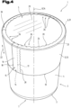
- Fig. 4 shows a three-dimensional view of an embodiment of a combination packaging container 1, whereby the example is representative of a multitude of conceivable shapes. Reference is made to the preceding descriptions, and to avoid unnecessary repetition, the special features of the illustrated variants are discussed below.
- the combination packaging container 1 shown is encased in an outer part 12.
- the container 2 is closed with a closure element 29 designed as a sealing plate or film, and a collar 31 or a flange 6 in the region of the open end 5 protrudes radially toward the longitudinal axis 8 or the cone axis 34, respectively.
- the open end 5 or the closure element 29 are partially covered by the folded or crimped folding area 24.
- the container 2 can be fixed and/or positioned in the region of the bottom 3 of the container 2 before being wrapped with the outer part 12 or before the outer part 12 is pushed on axially by coupling a coupling element with an alignment means, in particular with a groove or with a raised portion.
Landscapes
- Engineering & Computer Science (AREA)
- Mechanical Engineering (AREA)
- Ceramic Engineering (AREA)
- Packages (AREA)
Applications Claiming Priority (1)
| Application Number | Priority Date | Filing Date | Title |
|---|---|---|---|
| ATA50746/2023A AT526840B1 (de) | 2023-09-14 | 2023-09-14 | Kombi-Verpackungsbehälter mit einem Behälter und einem Außenteil |
Publications (1)
| Publication Number | Publication Date |
|---|---|
| EP4534432A1 true EP4534432A1 (fr) | 2025-04-09 |
Family
ID=92263656
Family Applications (1)
| Application Number | Title | Priority Date | Filing Date |
|---|---|---|---|
| EP24199763.4A Pending EP4534432A1 (fr) | 2023-09-14 | 2024-09-11 | Découpe, partie extérieure, conteneur d'emballage combiné avec un conteneur et une partie extérieure, procédé de fabrication d'un conteneur d'emballage combiné, procédé d'ouverture d'un contenaneur d'emballage combiné |
Country Status (2)
| Country | Link |
|---|---|
| EP (1) | EP4534432A1 (fr) |
| AT (1) | AT526840B1 (fr) |
Citations (5)
| Publication number | Priority date | Publication date | Assignee | Title |
|---|---|---|---|---|
| DE29708178U1 (de) * | 1997-05-06 | 1998-09-17 | Gizeh Verpackungen GmbH & Co. KG, 51702 Bergneustadt | Becher |
| WO2005056403A1 (fr) * | 2003-12-05 | 2005-06-23 | Charles Wilson | Enveloppe pour contenant |
| WO2020245148A1 (fr) | 2019-06-07 | 2020-12-10 | Greiner Packaging Ag | Pièce externe en forme de manchette ainsi que conteneur d'emballage combiné muni de celle-ci et procédé de séparation du conteneur d'emballage combiné |
| DE202020000644U1 (de) * | 2020-02-17 | 2021-05-18 | Gizeh Verpackungen Gmbh & Co. Kg | Verpackungsbecher |
| WO2022180079A1 (fr) * | 2021-02-25 | 2022-09-01 | Greiner Packaging Ag | Pièce externe en forme de manchon et contenant d'emballage combiné muni de celle-ci, et procédé pour séparer le contenant d'emballage combiné |
Family Cites Families (3)
| Publication number | Priority date | Publication date | Assignee | Title |
|---|---|---|---|---|
| US4150747A (en) * | 1977-05-09 | 1979-04-24 | The Continental Group, Inc. | Composite can |
| DE102011014844A1 (de) * | 2011-03-23 | 2012-09-27 | Optipack Gmbh | Behälter mit Banderole |
| CN112644838A (zh) * | 2020-12-02 | 2021-04-13 | 湖北克拉弗特实业有限公司 | 一种纸杯 |
-
2023
- 2023-09-14 AT ATA50746/2023A patent/AT526840B1/de active
-
2024
- 2024-09-11 EP EP24199763.4A patent/EP4534432A1/fr active Pending
Patent Citations (5)
| Publication number | Priority date | Publication date | Assignee | Title |
|---|---|---|---|---|
| DE29708178U1 (de) * | 1997-05-06 | 1998-09-17 | Gizeh Verpackungen GmbH & Co. KG, 51702 Bergneustadt | Becher |
| WO2005056403A1 (fr) * | 2003-12-05 | 2005-06-23 | Charles Wilson | Enveloppe pour contenant |
| WO2020245148A1 (fr) | 2019-06-07 | 2020-12-10 | Greiner Packaging Ag | Pièce externe en forme de manchette ainsi que conteneur d'emballage combiné muni de celle-ci et procédé de séparation du conteneur d'emballage combiné |
| DE202020000644U1 (de) * | 2020-02-17 | 2021-05-18 | Gizeh Verpackungen Gmbh & Co. Kg | Verpackungsbecher |
| WO2022180079A1 (fr) * | 2021-02-25 | 2022-09-01 | Greiner Packaging Ag | Pièce externe en forme de manchon et contenant d'emballage combiné muni de celle-ci, et procédé pour séparer le contenant d'emballage combiné |
Also Published As
| Publication number | Publication date |
|---|---|
| AT526840B1 (de) | 2024-08-15 |
| AT526840A4 (de) | 2024-08-15 |
Similar Documents
| Publication | Publication Date | Title |
|---|---|---|
| EP4265536B1 (fr) | Pièce externe en forme de manchette ainsi que conteneur d'emballage combiné muni de celle-ci et procédé de séparation du conteneur d'emballage combiné | |
| AT506750A1 (de) | Verfahren zur herstellung eines kombi - verpackungsbehälters sowie eines mantelförmigen aussenteils | |
| EP4298025B1 (fr) | Pièce externe en forme de manchon et contenant d'emballage combiné muni de celle-ci, et procédé pour séparer le contenant d'emballage combiné | |
| EP2254808B1 (fr) | Emballage composé d'un contenant et d'un couvercle | |
| WO2010010130A2 (fr) | Emballage refermable comportant une membrane pelable | |
| EP2206655B1 (fr) | Couvercle destiné à fermer une ouverture de récipient, emballage doté d'un récipient et d'un tel couvercle ainsi que procédé de scellage d'un récipient doté d'un tel couvercle | |
| DE9410586U1 (de) | Verpackung für Zigarettenbündel mit mehr als einem Öffnungsmittel | |
| WO2024013328A1 (fr) | Tube d'emballage recyclable | |
| EP2838807B1 (fr) | Récipient d'emballage combiné | |
| DE9111080U1 (de) | Verpackungsdose | |
| AT526840B1 (de) | Kombi-Verpackungsbehälter mit einem Behälter und einem Außenteil | |
| EP1486424A1 (fr) | Récipient d'emballage en plastique | |
| EP4298024B1 (fr) | Partie externe en forme de manchon, récipient d'emballage combiné équipé de celle-ci, et procédé de séparation du récipient d'emballage combiné | |
| AT525891B1 (de) | Außenteil und damit ausgestatteter Kombi-Verpackungsbehälter, Verfahren zur Herstellung und | |
| DE102013015581B3 (de) | Dichtscheibe zur lnduktionsversiegelung eines Behälters | |
| DE9305183U1 (de) | Tiefkühl-Schalenverpackung | |
| AT506749B1 (de) | Verfahren zur herstellung eines kombi-verpackungsbehälters | |
| DE29708178U1 (de) | Becher | |
| EP3107817B1 (fr) | Couvercle de fermeture muni d'une garantie d'inviolabilité et unité d'emballage munie dudit couvercle | |
| DE3043546A1 (de) | Zuschnitt fuer eine unbeschichtete behaelterschale | |
| DE102023200841A1 (de) | Wiederverschließbarer Behälter | |
| DE2339103B2 (de) | Schachtel mit einem Klarsichtfenster | |
| AT504479B1 (de) | Kombi-verpackungsbehälter | |
| DE202010002872U1 (de) | Faltschachtel und Zuschnitt zur Herstellung der Faltschachtel |
Legal Events
| Date | Code | Title | Description |
|---|---|---|---|
| PUAI | Public reference made under article 153(3) epc to a published international application that has entered the european phase |
Free format text: ORIGINAL CODE: 0009012 |
|
| STAA | Information on the status of an ep patent application or granted ep patent |
Free format text: STATUS: THE APPLICATION HAS BEEN PUBLISHED |
|
| AK | Designated contracting states |
Kind code of ref document: A1 Designated state(s): AL AT BE BG CH CY CZ DE DK EE ES FI FR GB GR HR HU IE IS IT LI LT LU LV MC ME MK MT NL NO PL PT RO RS SE SI SK SM TR |
|
| STAA | Information on the status of an ep patent application or granted ep patent |
Free format text: STATUS: REQUEST FOR EXAMINATION WAS MADE |
|
| 17P | Request for examination filed |
Effective date: 20251008 |