EP4534433A2 - Sac à porter en plastique - Google Patents
Sac à porter en plastique Download PDFInfo
- Publication number
- EP4534433A2 EP4534433A2 EP25159650.8A EP25159650A EP4534433A2 EP 4534433 A2 EP4534433 A2 EP 4534433A2 EP 25159650 A EP25159650 A EP 25159650A EP 4534433 A2 EP4534433 A2 EP 4534433A2
- Authority
- EP
- European Patent Office
- Prior art keywords
- side edge
- tapered
- wall
- transition
- layer
- Prior art date
- Legal status (The legal status is an assumption and is not a legal conclusion. Google has not performed a legal analysis and makes no representation as to the accuracy of the status listed.)
- Pending
Links
Images


Classifications
-
- B—PERFORMING OPERATIONS; TRANSPORTING
- B65—CONVEYING; PACKING; STORING; HANDLING THIN OR FILAMENTARY MATERIAL
- B65D—CONTAINERS FOR STORAGE OR TRANSPORT OF ARTICLES OR MATERIALS, e.g. BAGS, BARRELS, BOTTLES, BOXES, CANS, CARTONS, CRATES, DRUMS, JARS, TANKS, HOPPERS, FORWARDING CONTAINERS; ACCESSORIES, CLOSURES, OR FITTINGS THEREFOR; PACKAGING ELEMENTS; PACKAGES
- B65D31/00—Bags or like containers made of paper and having structural provision for thickness of contents
- B65D31/08—Bags or like containers made of paper and having structural provision for thickness of contents with block bottoms
-
- B—PERFORMING OPERATIONS; TRANSPORTING
- B65—CONVEYING; PACKING; STORING; HANDLING THIN OR FILAMENTARY MATERIAL
- B65D—CONTAINERS FOR STORAGE OR TRANSPORT OF ARTICLES OR MATERIALS, e.g. BAGS, BARRELS, BOTTLES, BOXES, CANS, CARTONS, CRATES, DRUMS, JARS, TANKS, HOPPERS, FORWARDING CONTAINERS; ACCESSORIES, CLOSURES, OR FITTINGS THEREFOR; PACKAGING ELEMENTS; PACKAGES
- B65D33/00—Details of, or accessories for, sacks or bags
- B65D33/06—Handles
- B65D33/10—Handles formed of similar material to that used for the bag
- B65D33/105—U-shaped
-
- B—PERFORMING OPERATIONS; TRANSPORTING
- B32—LAYERED PRODUCTS
- B32B—LAYERED PRODUCTS, i.e. PRODUCTS BUILT-UP OF STRATA OF FLAT OR NON-FLAT, e.g. CELLULAR OR HONEYCOMB, FORM
- B32B27/00—Layered products comprising a layer of synthetic resin
- B32B27/06—Layered products comprising a layer of synthetic resin as the main or only constituent of a layer, which is next to another layer of the same or of a different material
- B32B27/065—Layered products comprising a layer of synthetic resin as the main or only constituent of a layer, which is next to another layer of the same or of a different material of foam
-
- B—PERFORMING OPERATIONS; TRANSPORTING
- B32—LAYERED PRODUCTS
- B32B—LAYERED PRODUCTS, i.e. PRODUCTS BUILT-UP OF STRATA OF FLAT OR NON-FLAT, e.g. CELLULAR OR HONEYCOMB, FORM
- B32B27/00—Layered products comprising a layer of synthetic resin
- B32B27/06—Layered products comprising a layer of synthetic resin as the main or only constituent of a layer, which is next to another layer of the same or of a different material
- B32B27/08—Layered products comprising a layer of synthetic resin as the main or only constituent of a layer, which is next to another layer of the same or of a different material of synthetic resin
-
- B—PERFORMING OPERATIONS; TRANSPORTING
- B32—LAYERED PRODUCTS
- B32B—LAYERED PRODUCTS, i.e. PRODUCTS BUILT-UP OF STRATA OF FLAT OR NON-FLAT, e.g. CELLULAR OR HONEYCOMB, FORM
- B32B27/00—Layered products comprising a layer of synthetic resin
- B32B27/32—Layered products comprising a layer of synthetic resin comprising polyolefins
-
- B—PERFORMING OPERATIONS; TRANSPORTING
- B32—LAYERED PRODUCTS
- B32B—LAYERED PRODUCTS, i.e. PRODUCTS BUILT-UP OF STRATA OF FLAT OR NON-FLAT, e.g. CELLULAR OR HONEYCOMB, FORM
- B32B5/00—Layered products characterised by the non- homogeneity or physical structure, i.e. comprising a fibrous, filamentary, particulate or foam layer; Layered products characterised by having a layer differing constitutionally or physically in different parts
- B32B5/18—Layered products characterised by the non- homogeneity or physical structure, i.e. comprising a fibrous, filamentary, particulate or foam layer; Layered products characterised by having a layer differing constitutionally or physically in different parts characterised by features of a layer of foamed material
-
- B—PERFORMING OPERATIONS; TRANSPORTING
- B65—CONVEYING; PACKING; STORING; HANDLING THIN OR FILAMENTARY MATERIAL
- B65D—CONTAINERS FOR STORAGE OR TRANSPORT OF ARTICLES OR MATERIALS, e.g. BAGS, BARRELS, BOTTLES, BOXES, CANS, CARTONS, CRATES, DRUMS, JARS, TANKS, HOPPERS, FORWARDING CONTAINERS; ACCESSORIES, CLOSURES, OR FITTINGS THEREFOR; PACKAGING ELEMENTS; PACKAGES
- B65D31/00—Bags or like containers made of paper and having structural provision for thickness of contents
- B65D31/04—Bags or like containers made of paper and having structural provision for thickness of contents with multiple walls
-
- B—PERFORMING OPERATIONS; TRANSPORTING
- B65—CONVEYING; PACKING; STORING; HANDLING THIN OR FILAMENTARY MATERIAL
- B65D—CONTAINERS FOR STORAGE OR TRANSPORT OF ARTICLES OR MATERIALS, e.g. BAGS, BARRELS, BOTTLES, BOXES, CANS, CARTONS, CRATES, DRUMS, JARS, TANKS, HOPPERS, FORWARDING CONTAINERS; ACCESSORIES, CLOSURES, OR FITTINGS THEREFOR; PACKAGING ELEMENTS; PACKAGES
- B65D31/00—Bags or like containers made of paper and having structural provision for thickness of contents
- B65D31/10—Bags or like containers made of paper and having structural provision for thickness of contents with gusseted sides
-
- B—PERFORMING OPERATIONS; TRANSPORTING
- B65—CONVEYING; PACKING; STORING; HANDLING THIN OR FILAMENTARY MATERIAL
- B65D—CONTAINERS FOR STORAGE OR TRANSPORT OF ARTICLES OR MATERIALS, e.g. BAGS, BARRELS, BOTTLES, BOXES, CANS, CARTONS, CRATES, DRUMS, JARS, TANKS, HOPPERS, FORWARDING CONTAINERS; ACCESSORIES, CLOSURES, OR FITTINGS THEREFOR; PACKAGING ELEMENTS; PACKAGES
- B65D33/00—Details of, or accessories for, sacks or bags
- B65D33/02—Local reinforcements or stiffening inserts, e.g. wires, strings, strips or frames
-
- B—PERFORMING OPERATIONS; TRANSPORTING
- B32—LAYERED PRODUCTS
- B32B—LAYERED PRODUCTS, i.e. PRODUCTS BUILT-UP OF STRATA OF FLAT OR NON-FLAT, e.g. CELLULAR OR HONEYCOMB, FORM
- B32B2439/00—Containers; Receptacles
- B32B2439/02—Open containers
- B32B2439/06—Bags, sacks, sachets
Definitions
- the present invention relates to a plastic carrier bag, in particular one that is reusable and recyclable.
- Plastic carrier bags are generally more advantageous from an ecological and economic perspective than paper carrier bags if they are frequently reusable and easily recycled. Reusable plastic carrier bags must meet special stability criteria, especially since they are often larger and have carrying loops on the front and back. Conventional loop bags are found, for example, in the DE 10116 920 A1 , the WO 01/51372 A1 and the DE 40 12 897 A1 These state-of-the-art loop bags often lack sufficient mechanical stability for the repeated carrying of heavy loads.
- the present invention was therefore based on the object of providing plastic carrier bags, in particular large-sized reusable plastic carrier bags, which do not have the disadvantages of the carrier bags of the prior art and which are particularly suitable for the repeated reliable transport of even heavy loads and which can also be manufactured in a simple and cost-effective manner in machine series production.
- the plastic carrier bag according to the invention described above is characterized in that the at least one inner layer, in particular the inner layer, of the front wall and the at least one inner layer, in particular the inner layer, of the rear wall are formed in one piece, that the outer layers of the front and rear walls are formed in one piece and that the front wall and the rear wall merge into one another at the bottom end by folding over, in particular forming a bottom fold in this transition, wherein the transition, in particular the bottom fold, extends laterally from a first to an opposite second end, wherein when the front and rear walls are in contact with one another up to the transition, in particular the bottom fold (also called a "stackable storage state"), the lateral extent of the transition, in particular of the bottom fold, between the first and second ends is smaller than the lateral extent of the front and rear walls between the respective first and second side edges at the opening end, wherein the extent of the front and rear walls between the respective first and second side edges in the region of the lower third, in particular of the lower quarter, relative to the extension between the opening
- lateral dimension generally refers to the width of the side walls as well as the width of the front and rear walls, in other words, the distance between the opposite side edges of the side, front, and rear walls.
- the longitudinal dimension of the plastic carrier bag according to the invention accordingly extends perpendicularly thereto between the opening end and the fold or bottom fold.
- the descriptions of the plastic carrier bag according to the invention are based on a state in which the front and rear walls lie flat against one another on a level surface.
- the plastic carrier bags according to the invention can be stacked on top of one another in a flat state.
- This state can also be referred to as a "stackable storage state.”
- the bottom fold in the stackable storage state particularly preferably represents an outward-facing bottom fold.
- tapered/floor surface areas of the front and rear walls lie in the plane of the front and rear walls in the stackable storage state and are part of them, and that these tapered/floor surface areas become part of the floor area in the erected filling state, they are to be referred to as tapered/floor surface areas in the sense of the invention.
- plastic carrier bags with a large capacity are accessible using large-scale industrial production technology.
- This is achieved by providing side walls whose sections, tapering towards the bottom end, become part of a, in particular substantially rectangular or square, base surface during the filling process.
- this, in particular substantially rectangular or square base surface can also be obtained in the empty state by simply reaching into the bag interior and pulling apart the front and rear walls.
- the plastic carrier bag according to the invention is advantageously free-standing with an open opening cross-section, so that it can be filled with both hands.
- the first and second side walls each have a side fold, in particular one facing inwards. These side folds preferably extend to the transition, particularly preferably to the bottom fold, and preferably begin at the opening end of the plastic carrier bag.
- An embodiment has proven particularly advantageous in which the first and second side edges of the first side wall approach each other, in particular continuously, in the tapered/base area and converge in particular in the transition area, preferably the base fold, and in which the first and second side edges of the second side wall approach each other, in particular continuously, in the tapered/base area and converge in particular in the transition area, preferably the base fold.
- the first and second side walls preferably have a triangular basic shape in the tapered/base area. In other words, the opposite side edges of the first and second side walls converge in the tapered/base area and meet at the base end or at the transition from the front to the rear wall, in particular they open into the base fold.
- first and second side walls In the area of the opposing side edges of the first and second side walls, these are welded to the front and rear walls in the tapered/bottom area, preferably to the inside of the front and rear walls, particularly in the area of the respective side edges of the front and rear walls.
- this area can also be semicircular, rectangular, or square, for example, with the triangular configuration being preferred.
- the front wall tapers in a straight line from the beginning of the tapered/bottom area on the first side edge, facing the opening end, to the first end of the transition, in particular the bottom fold.
- the front wall tapers in a straight line from the beginning of the tapered/bottom area on the second side edge, facing the opening end, to the second end of the transition, in particular the bottom fold.
- the rear wall can taper in a straight line from the beginning of the tapered/bottom area on the first side edge, facing the opening end, to the first end of the transition, in particular the bottom fold.
- the rear wall tapers in a straight line from the beginning of the tapered/bottom area tapered straight at the second side edge to the second end of the transition, especially the bottom fold.
- the first and second side panels are conveniently based on separate material cuts. These material cuts can be individually adapted to the size and shape of the front and back panels or to the design of the bag's base body, which consists of the front and back panels.
- Very practical embodiments of the plastic carrier bags according to the invention also provide, in particular, that the extension from the first to the second side edge of the first side wall substantially corresponds, in particular corresponds, to the sum of the extension of the tapered/bottom surface area of the front wall, calculated from the transition, in particular the bottom fold, and the extension of the tapered/bottom surface area of the rear wall, calculated from the transition, in particular the bottom fold.
- the extension from the first to the second side edge of the second side wall substantially corresponds, in particular corresponds, to the sum of the extension of the tapered/bottom surface area of the front wall, calculated from the transition, in particular the bottom fold, and the extension of the tapered/bottom surface area of the rear wall, calculated from the transition, in particular the bottom fold.
- the front wall tapers in a straight line from the beginning of the tapered/bottom area on the first side edge facing the opening end to the first end of the transition, in particular the bottom fold, and/or, in particular and, that the front wall tapers in a straight line from the beginning of the tapered/bottom area on the second side edge facing the opening end to the second end of the transition, in particular the bottom fold, and that the rear wall tapers in a straight line from the beginning of the tapered/bottom area on the first side edge facing the opening end to the first end of the transition, in particular the bottom fold, and/or, in particular and, that the rear wall tapers in a straight line from the beginning of the tapered/bottom area on the second side edge facing the opening end to the second end of the transition, in particular the bottom fold rejuvenated.
- the front wall tapers in a concave shape from the beginning of the tapered/bottom surface area on the first side edge facing the opening end to the first end of the transition, in particular the bottom fold, and/or, in particular and, that the front wall tapers in a concave shape from the beginning of the tapered/bottom surface area on the second side edge facing the opening end to the second end of the transition, in particular the bottom fold, and that the rear wall tapers in a concave shape from the beginning of the tapered/bottom surface area on the first side edge facing the opening end to the first end of the transition, in particular the bottom fold, and/or, in particular and, that the rear wall tapers in a concave shape from the beginning of the tapered/bottom surface area on the second side edge facing the opening end to the second end of the transition, in particular the bottom fold,
- a convex-shaped taper can also be provided.
- the front wall tapers convexly from the start of the tapered/bottom surface area on the first side edge facing the opening end to the first end of the transition, in particular the bottom fold, and/or, in particular and, that the front wall tapers convexly from the start of the tapered/bottom surface area on the second side edge facing the opening end to the second end of the transition, in particular the bottom fold, and that the rear wall tapers convexly from the start of the tapered/bottom surface area on the first side edge facing the opening end to the first end of the transition, in particular the bottom fold, and/or, in particular and, that the rear wall tapers convexly from the start of the tapered/bottom surface area on the second side edge facing the opening end to the second end of the transition, in particular the bottom fold.
- the front wall tapers at the beginning of the tapered/bottom surface area on the first side edge facing the opening end in the direction of the opposite second side edge in a first section and in the section adjoining up to the first end of the transition tapers less sharply or no longer and/or, in particular and, that the front wall tapers at the beginning of the tapered/bottom surface area on the second side edge facing the opening end in the direction of the opposite first side edge in a first section and in the section adjoining up to the second end of the transition, in particular the bottom fold, tapers less sharply or no longer and that the rear wall tapers at the beginning of the tapered/bottom surface area on the first side edge facing the opening end in the direction of the opposite second side edge in a first section and in the section adjoining up to the first end of the transition, in particular the bottom fold less sharply or no longer tapered and/or, in particular, that the rear wall tapers at the beginning of the tapered/bottom surface area on the second side edge
- the tapered/bottom surface area can be initiated by changing the course of the first and second side edges of the front and rear walls by 90° in each case with respect to the course of these side edges beyond the tapered/bottom surface area, wherein This curve then changes again by 90° towards the transition from the front to the rear wall.
- the width of the tapered/floor area remains constant.
- a particularly high degree of mechanical stability is also achieved by the first side wall, the multi-layer front wall and the multi-layer rear wall being welded to one another adjacent to or in the region of the first end of the transition, in particular the bottom fold, and/or, in particular, by the second side wall, the multi-layer front wall and the multi-layer rear wall being welded to one another adjacent to or in the region of the second end of the transition, in particular the bottom fold.
- the first side wall, the front wall and the rear wall are welded to one another in a first area adjacent to or in the region of the first end of the transition, in particular the bottom fold.
- the eight-layer welded areas are obtained.
- the previously specified embodiments generally result in a particularly stable base surface when erected and filled, and in particular in a plastic carrier bag that can withstand high mechanical loads and is often reusable.
- the plastic carrier bags according to the invention possess a pronounced mechanical stability and sturdiness even when the first and second side walls, unlike the front and rear walls, are designed as single-layered.
- first and second side walls are designed as multi-layered, in particular double-layered. This can further increase stability.
- even single-layered first and second side walls already provide even greater stability and, in particular, increased Stability is achieved by having a seam at the opening end. This seam can, for example, be designed and maintained in the same way as the reinforcement areas of the front and rear walls, i.e. with the aid of a continuation section adjoining the side wall which is folded over.
- this continuation section can be simply folded over onto the inside or outside, in particular the inside, i.e. forming only one layer.
- the seam can also be formed by a separate strip of plastic material.
- the continuation section and the strip of plastic material are preferably joined to the inside or outside of the first and second side walls by welding.
- Such plastic carrier bags according to the invention achieve the object underlying the invention particularly reliably, in which the holding loop connected to the front wall and the holding loop connected to the rear wall is welded in its first and second connection areas to the single-layer or multi-layer, in particular multi-layer, plastic film strip of the reinforcement area and also to the at least one inner layer, in particular the inner layer, and the outer layer, and wherein the single-layer or multi-layer, in particular multi-layer, plastic film strip of the reinforcement area of the front wall is fastened to the inner or outer layer from or at a distance from the first side edge in the direction of or up to the second side edge by means of welding, and wherein the single-layer or multi-layer, in particular multi-layer, plastic film strip of the reinforcement area of the rear wall is fastened to the inner or outer layer from or at a distance from the first side edge in the direction of or up to the second side edge by means of welding, wherein the first and second connection areas of the holding loop connected to the front wall and the first and second connection areas of the holding loop connected to the rear
- Particularly suitable plastic carrier bags according to the invention are also characterized in that in the section which is not the tapered/bottom area, the first side wall is welded in the region of its first side edge to the front wall, in particular along its first side edge, and in the region of the second side edge to the rear wall, in particular along its first side edge, wherein in the section which is not the tapered/bottom area, the second side wall is welded in the region of its first side edge to the front wall, in particular along its second side edge, and in the region of the second side edge to the rear wall, in particular along its second side edge.
- the plastic carrier bags according to the invention are preferably made of thermoplastics, with polyolefinic thermoplastics, especially polyethylene, being preferred. In these cases, the connection by welding usually represents a thermoplastic weld. Accordingly, the plastic carrier bags according to the invention are particularly preferably made entirely of thermoplastics, especially polyolefinic thermoplastics such as polyethylene. This results in single-variety plastic bags that are particularly sustainably recyclable.
- the outer layer of the front and back walls of the plastic carrier bag according to the invention usually represents a single layer. If there is another layer on the inside and adjacent to the outer layer, this is to be counted as one of the inside layers or represents the inner layer. If the continuation section is integral with the outer layer, this continuation section must also necessarily be a single layer.
- the single-layer nature of the outer layer of the front and back walls does not preclude the outer layer from being multi-layered and, for example, from being present as a coextruded film.
- a single-layer outer layer can also have a laminated layer on the inside and/or outside without losing the character of the single layer. In multi-layer systems, the layers are accordingly closely bonded.
- outer layer and the inner layer or the majority of the inside layers are accordingly, in a preferred embodiment, connected to one another only by welding along their side edges.
- outer layer and the inner layer or the majority of the inner layers are partially connected to one another, e.g. via isolated welding or adhesive points, in particular welding points.
- the holding loop connected to the front wall via its first and second connection areas and the holding loop connected to the rear wall via its first and second connection areas in the area from the respective first to the second connection area at least in sections has a first flexible, in particular tubular, hollow body and/or a single- or multi-layer material strip, in particular plastic material strip, which does not form a hollow body and which is at least in sections, in particular substantially completely, enveloped by a second flexible, in particular tubular, hollow body.
- the first flexible, in particular tubular, hollow body is formed from a first flexible plastic material strip with opposite first and second longitudinal side edges, the opposite first and second longitudinal side edges of which are welded and/or glued to one another in an overlapping region and/or, preferably and, in which the second flexible, in particular tubular, hollow body is formed from a second flexible plastic material strip with opposite first and second longitudinal side edges, the opposite first and second longitudinal side edges of which are welded and/or glued to one another in a second overlapping region.
- the first and second flexible plastic material strips for example in the form of polyolefin film strips, in particular polyethylene film strips, can have a rectangular shape when spread out flat.
- the longitudinal edges of these material strips can then be moved toward each other to form the first and second, in particular tubular, hollow bodies and connected to each other in the overlapping region.
- the first longitudinal side edge can rest against the second longitudinal side edge both above and below the latter in an overlapping region.
- a particularly high degree of strength is achieved in particular by the fact that the first plastic material strip of the first flexible, in particular tubular, hollow body and the second plastic material strip of the second flexible, in particular tubular, hollow body are welded and/or glued to one another at least in sections, in particular along the first and second overlapping regions. It has often proven expedient to weld the first and second plastic material strips in the first and/or second overlapping region in a single process step, i.e. essentially simultaneously. This creates a uniform weld seam extending along the holding loop, in particular a tubular one.
- This embodiment has the further advantage that the first and the second flexible hollow body are connected to one another in the region of this uniform weld seam, which results in further increased mechanical strength.
- the first and the second hollow body, in particular a tubular one can also be connected to one another in regions or continuously along their entire length, in particular along a connecting strip, without the first and second overlapping regions themselves overlapping in this connection region.
- the first flexible, in particular tubular, hollow body is formed from a first flexible plastic material strip with opposite first and second longitudinal side edges and that the second flexible, in particular tubular, hollow body is formed from a second flexible plastic material strip with opposite first and second longitudinal side edges, wherein in the overlapping region of the first and second longitudinal side edges of the first flexible plastic material strip, the first longitudinal side edge of the first plastic material strip is welded and/or glued to the first longitudinal side edge of the second material strip and this first longitudinal side edge of the second plastic material strip is welded to the second longitudinal side edge of the first plastic material strip and wherein in the overlapping region of the first and second longitudinal side edges of the second flexible plastic material strip, the second longitudinal side edge of the first plastic material strip is welded to the second longitudinal side edge of the second material strip and this second longitudinal side edge of the first plastic material strip is welded to the first longitudinal side edge of the second plastic material strip and/or glued.
- a further advantageous refinement in particular of the preceding embodiment, provides that in the first and/or second connection area of the first and/or second retaining loop, in particular the flat-pressed first and/or second retaining loop, the connection side is that side of the retaining loop, in particular the flat-pressed first and second, which does not have the overlapping areas of the opposite first and second longitudinal side edges of the first and second flexible plastic material strips of the first and second flexible hollow bodies. It has surprisingly been shown that particularly good mechanical stability and tear resistance are achieved in this way.
- the second flexible, in particular tubular, hollow body of the holding loop of the front and/or rear wall in particular the second flexible plastic material strip forming or containing the second flexible, in particular tubular, hollow body of the holding loop of the front and/or rear wall, is based on a plastic material that is at least partially transparent, in particular polyethylene, which is printable or printed on the inside, in particular by means of a counter-printing process. Since, in the described embodiment, the print is present on the inside of the second hollow body of the holding loop, it is not impaired when worn, for example by abrasion.
- the first flexible, in particular tubular, hollow body or the single- or multi-layer material strip, in particular a plastic material strip, which does not form a hollow body, of the holding loop of the front and/or rear wall is printable or printed on the outside at least in sections
- the second flexible, in particular tubular, hollow body of the holding loop is based on or consists of a plastic material, in particular polyethylene, which is at least partially transparent.
- the preceding embodiments of the plastic carrier bag according to the invention also allow the holding loop(s) to be used as an information or advertising medium carrier or for the attachment of design elements.
- the outer layer of the front and/or rear wall is based on or consists of a plastic material, in particular polyethylene, which is at least partially transparent and which is printable or printed on the inside, at least partially, in particular by means of a counterprinting process.
- the plastic carrier bag according to the invention alternatively or additionally comprises at least one inner layer, in particular the inner layer, of the front and/or rear wall, which is at least partially printable or printed on the outside, and wherein the outer layer is based on or consists of a plastic material, in particular polyethylene, which is at least partially transparent.
- a particularly high degree of stability and tear resistance is also achieved by using a non-foamed plastic film, preferably a non-foamed polyolefin film, particularly preferably a non-foamed polyethylene film and in particular a non-foamed LD polyethylene film, for an outer layer of a plastic carrier bag according to the invention in the aforementioned embodiments.
- a non-foamed plastic film preferably a non-foamed polyolefin film, particularly preferably a non-foamed polyethylene film and in particular a non-foamed LD polyethylene film
- the combination of a foamed plastic inner layer and a non-foamed plastic outer layer surprisingly leads to particularly mechanically resilient and permanently stable plastic carrier bags.
- plastic carrier bags are particularly preferred in which the first flexible, in particular tubular, hollow body or the single- or multi-layer material strip of the holding loop of the front and/or rear wall, which does not form a hollow body, in particular the first flexible plastic material strip, is formed or consists of foamed polymer material, preferably foamed polyethylene, and particularly preferably foamed LD polyethylene, and wherein preferably the second flexible, in particular tubular, hollow body of the holding loop of the front and/or rear wall, in particular the second flexible plastic material strip, is formed or consists of non-foamed polymer material, preferably non-foamed polyethylene, and particularly preferably non-foamed LD polyethylene.
- the outer layer, the single- or multi-layer, in particular double-layer, plastic film strip of the reinforcement area, in particular the continuation section of the inner or outer layer, and/or the at least one inner layer, in particular the inner layer, of the front and/or rear wall are expediently in film form.
- a particularly high degree of stability and tear resistance is also achieved in the above-mentioned embodiments of a plastic carrier bag according to the invention in that the first and second connection areas of the holding loops connected to the front wall and/or to the rear wall, which are obtained in particular by welding, are spaced apart from the first and/or second connecting strips, in particular do not have an overlap with the first and/or second connecting strips.
- Polypropylene can also be used as an alternative to polyethylene.
- Copolymers with ethylene or propylene as the main component are also suitable, wherein for the further comonomers, for example, propylene or ethylene and/or butene, for example 1-butene, or butadiene can be used.
- the outer layer, the single- or multi-layer, in particular double-layer, plastic film strip of the reinforcement area, in particular the continuation section of the outer layer, and the at least one inner layer, in particular the inner layer, of the front and rear walls as well as the holding loops connected to the front wall and to the rear wall, in particular their first and/or second flexible plastic material strips and/or the single- or multi-layer material strips not forming a hollow body, as well as the first and second side walls are formed or consist of polyolefins, preferably polyethylene, particularly preferably HD or LD polyethylene, in particular LD polyethylene.
- a uniform plastic material such as polypropylene or polyethylene, preferably polyethylene, and particularly preferably low-density polyethylene, is used for all components of the plastic carrier bag according to the invention, for example, for the inner and outer layers of the front and rear walls, for the holding loops of the front and rear walls, and for the first and second side walls.
- a uniform plastic material such as polypropylene or polyethylene, preferably polyethylene, and particularly preferably low-density polyethylene
- the at least one inner layer, in particular the inner layer, of the front and/or, in particular, rear wall comprises or represents a foamed plastic film, preferably a foamed polyolefin film, particularly preferably a foamed polyethylene film and in particular a foamed LD polyethylene film.
- a foamed plastic film preferably a foamed polyolefin film, particularly preferably a foamed polyethylene film and in particular a foamed LD polyethylene film.
- the first flexible, in particular tubular, hollow body or the one- or multi-layer material strips which do not form a hollow body comprise or consist of a foamed plastic film, preferably a foamed polyolefin film, particularly preferably a foamed polyethylene film and in particular a foamed LD polyethylene film.
- LD polyethylene is particularly preferred among polyethylenes.
- the holding loop connected to the front wall and/or to the rear wall, in particular on the inside is welded and/or glued in its first and second connection areas, directly or indirectly, to the single-layer or multi-layer, in particular multi-layer, plastic film strip of the reinforcement area, and to the at least one inner layer, in particular the inner layer, and the outer layer, wherein in these first and second connection areas at least the inside of the second hollow body of the holding loop, in particular the inwardly facing side of the second flexible plastic material strip, is welded and/or glued to the outside of the first hollow body or the facing side of the single-layer or multi-layer material strip not forming a hollow body, in particular the outwardly facing side of the first flexible plastic material strip.
- connection to the at least one inner layer, in particular the inner layer, and the outer layer is usually made indirectly, i.e., via the adjacent adjacent layer.
- connection to the at least one inner layer, in particular the inner layer, or the outer layer, as well as the layer(s) of the plastic film strip of the reinforcement area is usually made indirectly, i.e., via the adjacent adjacent layer.
- the molten material of the layers involved may become mixed during welding, making it impossible to clearly assign the material to the layers.
- the second flexible, in particular tubular, hollow body, in particular the second flexible plastic material strip, of the retaining loop of the front and/or rear wall has an embossed pattern at least in sections, in particular over its entire surface.
- embossed patterns can be reliably and permanently produced, for example, when using thermoplastic materials, such as polyolefins, through the application of heat and pressure.
- the plastic carrier bags according to the invention it has proven pragmatic to form the opening edge by a fold at the upper end of the outer layer or in the transition area from the outer layer to the continuation section.
- the outer layer of the front and/or rear wall is additionally welded and/or glued to the outer side of the at least one inner layer, in particular the inner layer, along the extension from or at a distance from the first side edge in the direction of or up to the second side edge, in particular with a continuous longitudinal weld, to form a second connecting strip, wherein this second connecting strip is preferably spaced closer to the lower edge of the reinforcement region than to its upper edge, in particular at or adjacent to the lower edge of the reinforcement region.
- the first and second connecting strips are substantially overlapping, at least in sections, preferably completely.
- the plastic carrier bag according to the invention in particular the single-layer plastic carrier bag according to the invention, can be designed in such a way that the outer layer, the single-layer or multi-layer, in particular double-layer, plastic film strip of the reinforcement area, in particular the continuation section of the inner or outer layer, and/or the at least one inner layer, in particular the inner layer, of the front and/or rear wall, the first and the second side wall as well as the holding loops connected to the front wall and/or the rear wall, in particular their first and/or second flexible plastic material strips or the multi-layer, non-hollow material strips contain or consist of recycled plastic material, in particular recycled polyolefins, for example polyethylene.
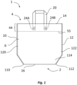
- Figure 1 shows a schematic front view of a plastic carrier bag (1) according to the invention.
- the double-layered front wall (6) merges integrally into the double-layered rear wall (8) by folding over, forming a bottom fold (16) in the transition.
- the bottom fold (16) has a lateral extension from the first end (110) to the opposite second end (112) that is less than the lateral extension of the front and rear walls in the region of the opening end (4).
- the front and rear walls (6, 8) have, in the region of the opening end (4), a reinforcement region (44, 46) extending to the opening end, each containing a double-layered plastic film strip (106, 108) fastened to the inside of the front wall (6) and to the inside of the rear wall (8) respectively, and extending from the first side edge (10) to the second side edge (12).
- This double-layered plastic film strip (106, 108) can be a separate component, but preferably represents an integral, i.e. one-piece, part of the outer layer and is accordingly formed from a continuation section of the outer layer of the front or rear wall. This continuation section initially forms the opening edge (14) by folding over.
- this continuation section is welded along a connecting strip (55) to the inner layer (28) and, via this, also to the outer layer (30).
- the front wall (6) and the rear wall (8) are each connected to the bag body by a holding loop (20, 22) via their first and second connection areas (24A, 24B; 26A, 26B).
- the first and second connection areas (24A, 24B; 26A, 26B) of the holding loops (20, 22) for the front and rear walls lie entirely in the respective reinforcement areas (44, 46) and do not overlap with the connecting strip (55).
- Figure 2 shows a schematic side view of the cut of a first side wall (102) of the plastic carrier bag (1) according to the invention according to Fig. 1 .
- the first and second side edges (116, 118) run parallel to each other in the area beginning with the upper end (4) of the plastic carrier bag (1) according to the invention.
- the plastic carrier bag (1) according to the invention merges into the tapered/bottom area (114, 114') (see Fig. 1 )
- the parallel course of these side edges ends and they converge symmetrically to meet at a point (16') lying on the longitudinal center axis of the side wall.
- these tapered sections (124, 126) of the first and second side walls (102, 104) have a triangular shape. If this side wall is a gusseted wall, the gusset runs regularly along the longitudinal center axis.
- FIG. 3 a schematic perspective view of the plastic carrier bag (1) according to the invention according to Fig. 1 in the erected, filled state.
- the base surface is formed by parts of the front and rear walls (6, 8) in the tapered/base surface area (114, 114') as well as by the triangular tapered/base surface areas (124, 126) of the first and second side walls (102, 104).
- the side walls (102, 104) are welded along their side edges (116, 118; 116', 118') to the inner sides of the front and rear walls (6, 8), likewise along their side edges (10, 12; 10', 12'), forming weld seams (120, 122; 120', 122').
- Figure 6 shows the upper region of the plastic carrier bag (1) according to the invention.
- the extension sections (36, 38) are folded over the inner layers (28, 32) and also folded inward again, thus forming a double layer.
- These double-layered extension sections (36, 38) are welded to one another, to the inside of the inner layer (28, 32) to form the connecting regions (52, 52'), and furthermore, the inner layer (28, 32) is also welded to the respective outer layer (30, 34) to form the connecting regions (54, 54').
- the connecting regions (52, 52') and (54, 54') each overlap and form a uniform welded section (55, 55'), which can in particular also be obtained in a single welding step.
- FIG. 6 The holding loops (20, 22), also shown in detail, are welded on the inside to the folded, double-layered extension sections (36, 38) in the illustrated first connection areas (24A, 26A). Furthermore, in these connection areas (24A, 26A), the outer layer (30, 34), the inner layer (28, 30) and the folded extension section (36, 38) are each welded to one another. In this way, a very stable, mechanically strong plastic carrier bag (1) is obtained. Furthermore, the illustrated internal attachment of the holding loops ensures uncomplicated filling of the plastic carrier bags according to the invention.
- the carrying loops prevent the upper ends or opening edges from serving as abutting edges when filling with piece goods.
- Figure 7 shows a schematic front view of another embodiment of a plastic carrier bag according to the invention.
- This embodiment differs from the embodiment according to Figure 1 in that in the tapered/bottom surface area (114), which lies in the lower third of the plastic carrier bag according to the invention, the first and second side edges (10, 12) of the front and rear walls (6, 8) taper in a concave manner in the direction of the first and second ends (110, 112) of the bottom fold (16).
- Figure 9 shows a schematic plan view of a blank (100) for the outer layer (30, 34) of the front and rear walls (6, 8) of this embodiment of a plastic carrier bag (1) according to the invention.
- the outer layer of the front and rear walls (6, 8) are also formed in one piece here.
- extension sections 36, 38
- double-layered plastic material strip of the reinforcement area 44, 46.
- semicircular material recesses (18, 18') which, after the front and rear wall sections have been folded over, form one another, including the one-piece inner layers of the front and rear walls, and joining with the first and second side walls form the tapered/bottom surface area (114, 114').
- Figure 8 shows a schematic front view of another embodiment of a plastic carrier bag according to the invention.
- This embodiment differs from the embodiment according to Figure 1 in that in the tapered/bottom surface area (114), which lies in the lower third of the plastic carrier bag according to the invention, the first and second side edges (10, 12) of the front and rear walls (6, 8) taper seamlessly, i.e., forming a right angle each time.
- the tapered/bottom surface area (114) thus obtained then has a uniform width or lateral extent up to the bottom fold (16).
- Figure 10 shows a schematic plan view of a blank (100) for the outer layer (30, 34) of the front and rear walls (6, 8) of this embodiment of a plastic carrier bag (1) according to the invention.
- the outer layer of the front and rear walls (6, 8) are also formed in one piece here. They each also contain the respective extension sections (36, 38), which, by folding over, form the opening edge (14) and the double-layered plastic material strip of the reinforcement area (44, 46).
- rectangular material recesses (18, 18') which, after the front and rear wall sections have been folded over one another, including the one-piece inner layers of the front and rear walls, and joined together with the first and second side walls, form the tapered/bottom surface area (114, 114').
Landscapes
- Engineering & Computer Science (AREA)
- Mechanical Engineering (AREA)
- Bag Frames (AREA)
Priority Applications (1)
| Application Number | Priority Date | Filing Date | Title |
|---|---|---|---|
| EP25159650.8A EP4534433A3 (fr) | 2023-07-05 | 2023-07-05 | Sac à porter en plastique |
Applications Claiming Priority (2)
| Application Number | Priority Date | Filing Date | Title |
|---|---|---|---|
| EP23183739.4A EP4488191A1 (fr) | 2023-07-05 | 2023-07-05 | Sac à porter en plastique |
| EP25159650.8A EP4534433A3 (fr) | 2023-07-05 | 2023-07-05 | Sac à porter en plastique |
Related Parent Applications (1)
| Application Number | Title | Priority Date | Filing Date |
|---|---|---|---|
| EP23183739.4A Division EP4488191A1 (fr) | 2023-07-05 | 2023-07-05 | Sac à porter en plastique |
Publications (2)
| Publication Number | Publication Date |
|---|---|
| EP4534433A2 true EP4534433A2 (fr) | 2025-04-09 |
| EP4534433A3 EP4534433A3 (fr) | 2025-06-04 |
Family
ID=87158037
Family Applications (2)
| Application Number | Title | Priority Date | Filing Date |
|---|---|---|---|
| EP23183739.4A Pending EP4488191A1 (fr) | 2023-07-05 | 2023-07-05 | Sac à porter en plastique |
| EP25159650.8A Pending EP4534433A3 (fr) | 2023-07-05 | 2023-07-05 | Sac à porter en plastique |
Family Applications Before (1)
| Application Number | Title | Priority Date | Filing Date |
|---|---|---|---|
| EP23183739.4A Pending EP4488191A1 (fr) | 2023-07-05 | 2023-07-05 | Sac à porter en plastique |
Country Status (6)
| Country | Link |
|---|---|
| US (1) | US20250011042A1 (fr) |
| EP (2) | EP4488191A1 (fr) |
| AU (1) | AU2024204251A1 (fr) |
| CL (1) | CL2024002053A1 (fr) |
| CO (1) | CO2024008910A1 (fr) |
| MX (1) | MX2024008459A (fr) |
Citations (2)
| Publication number | Priority date | Publication date | Assignee | Title |
|---|---|---|---|---|
| DE4012897A1 (de) | 1990-02-26 | 1991-08-29 | Windmoeller & Hoelscher | Textiltragetasche aus thermoplastischem kunststoff und verfahren zu ihrer herstellung |
| DE10116920A1 (de) | 2001-04-05 | 2002-10-24 | Lemo Maschb Gmbh | Tragetasche aus Kunststoff und Verfahren zu ihrer Herstellung |
Family Cites Families (6)
| Publication number | Priority date | Publication date | Assignee | Title |
|---|---|---|---|---|
| NL98445B (fr) * | 1940-07-24 | 1946-12-16 | ||
| GB1000643A (en) * | 1963-03-29 | 1965-08-11 | Metal Box Co Ltd | Improvements in or relating to sacks |
| DE3144702A1 (de) * | 1981-11-11 | 1983-05-19 | LP-Plast Gesellschaft zur Verarbeitung von Kunststoffen mbH, 5000 Köln | Isolierbeutel |
| DE20106175U1 (de) * | 2001-04-07 | 2002-08-14 | Bischof und Klein GmbH & Co. KG, 49525 Lengerich | Seitenfaltenbeutel oder -sack aus flexiblem schweißbarem Material |
| DE202017105180U1 (de) * | 2017-08-28 | 2017-11-03 | Papier-Mettler Kg | Kunststofftragetasche und Halteschlaufe für eine Kunststofftragetasche |
| DE102020004962A1 (de) * | 2020-08-14 | 2022-02-17 | Mondi Ag | Verpackungsbeutel auf Papierbasis sowie Verfahren zur Herstellung eines Verpackungsbeutels |
-
2023
- 2023-07-05 EP EP23183739.4A patent/EP4488191A1/fr active Pending
- 2023-07-05 EP EP25159650.8A patent/EP4534433A3/fr active Pending
-
2024
- 2024-06-21 AU AU2024204251A patent/AU2024204251A1/en active Pending
- 2024-07-03 US US18/763,356 patent/US20250011042A1/en active Pending
- 2024-07-04 CO CONC2024/0008910A patent/CO2024008910A1/es unknown
- 2024-07-04 MX MX2024008459A patent/MX2024008459A/es unknown
- 2024-07-05 CL CL2024002053A patent/CL2024002053A1/es unknown
Patent Citations (2)
| Publication number | Priority date | Publication date | Assignee | Title |
|---|---|---|---|---|
| DE4012897A1 (de) | 1990-02-26 | 1991-08-29 | Windmoeller & Hoelscher | Textiltragetasche aus thermoplastischem kunststoff und verfahren zu ihrer herstellung |
| DE10116920A1 (de) | 2001-04-05 | 2002-10-24 | Lemo Maschb Gmbh | Tragetasche aus Kunststoff und Verfahren zu ihrer Herstellung |
Also Published As
| Publication number | Publication date |
|---|---|
| CL2024002053A1 (es) | 2024-12-06 |
| MX2024008459A (es) | 2025-02-10 |
| EP4488191A1 (fr) | 2025-01-08 |
| CO2024008910A1 (es) | 2025-07-07 |
| AU2024204251A1 (en) | 2025-01-23 |
| EP4534433A3 (fr) | 2025-06-04 |
| US20250011042A1 (en) | 2025-01-09 |
Similar Documents
| Publication | Publication Date | Title |
|---|---|---|
| DE69726220T2 (de) | Seitenfaltbeutel mit Reissverschluss sowie Verfahren zu seiner Herstellung | |
| DE3629563C2 (fr) | ||
| EP0383020B2 (fr) | Sac | |
| EP0627355B1 (fr) | Dispositif de fabrication de sacs tubulaires | |
| EP2354026B1 (fr) | Sachet à soufflets latéraux et procédé de fabrication d'un sachet à soufflets latéraux | |
| DE3508123A1 (de) | Verfahren zum herstellen einer tragetasche sowie tragetasche | |
| WO2005110878A1 (fr) | Sachet a fond plat, a plis lateraux rentrants | |
| DE1900337B2 (de) | Verfahren zum herstellen von tragetaschen aus kunststoffolie | |
| DE1943027U (de) | Aus einem schlauch aus thermoplastischer kunststoffolie hergestellte tasche. | |
| DE60003241T2 (de) | Tragezugbeutel mit tragegriff | |
| EP3812294B1 (fr) | Sac à poignée en matière plastique | |
| EP3889060B1 (fr) | Agencement de sachets en feuille, ainsi que procédé de formation d'un agencement de sachet en feuille | |
| EP4534433A2 (fr) | Sac à porter en plastique | |
| EP0989069B1 (fr) | Sachet tenant debout en matériau soudable | |
| EP4570691A1 (fr) | Sac à porter en plastique | |
| EP4570692A1 (fr) | Sac à porter en plastique | |
| EP3875387B9 (fr) | Sac à fond en film plastique et son utilisation ainsi que découpe pour un sac à fond en film plastique | |
| DE1948231A1 (de) | Verfahren zur Herstellung von Trinktuben | |
| EP3812295B1 (fr) | Pochette d'expédition en matière plastique ainsi qu'utilisation de la pochette d'expédition en matière plastique | |
| DE1536284A1 (de) | Tragetasche aus thermoplastischer Kunststoffolie und Verfahren zu ihrer Herstellung | |
| DE2143819A1 (de) | Tragbeutel aus kunststoffolie | |
| DE1479837B2 (de) | Tragbeutel und verfahren zu seiner herstellung | |
| DE19605259A1 (de) | Tragtasche und Verfahren zu ihrer Herstellung | |
| EP1935799B1 (fr) | Poches à ourlets | |
| DE1479837C (de) | Tragbeutel und Verfahren zu seiner Herstellung |
Legal Events
| Date | Code | Title | Description |
|---|---|---|---|
| PUAI | Public reference made under article 153(3) epc to a published international application that has entered the european phase |
Free format text: ORIGINAL CODE: 0009012 |
|
| STAA | Information on the status of an ep patent application or granted ep patent |
Free format text: STATUS: THE APPLICATION HAS BEEN PUBLISHED |
|
| AC | Divisional application: reference to earlier application |
Ref document number: 4488191 Country of ref document: EP Kind code of ref document: P |
|
| AK | Designated contracting states |
Kind code of ref document: A2 Designated state(s): AL AT BE BG CH CY CZ DE DK EE ES FI FR GB GR HR HU IE IS IT LI LT LU LV MC ME MK MT NL NO PL PT RO RS SE SI SK SM TR |
|
| REG | Reference to a national code |
Ref country code: DE Ref legal event code: R079 Free format text: PREVIOUS MAIN CLASS: B65D0030200000 Ipc: B65D0030080000 |
|
| PUAL | Search report despatched |
Free format text: ORIGINAL CODE: 0009013 |
|
| AK | Designated contracting states |
Kind code of ref document: A3 Designated state(s): AL AT BE BG CH CY CZ DE DK EE ES FI FR GB GR HR HU IE IS IT LI LT LU LV MC ME MK MT NL NO PL PT RO RS SE SI SK SM TR |
|
| RIC1 | Information provided on ipc code assigned before grant |
Ipc: B65D 30/20 20060101ALI20250428BHEP Ipc: B65D 30/18 20060101ALI20250428BHEP Ipc: B65D 30/08 20060101AFI20250428BHEP |
|
| P01 | Opt-out of the competence of the unified patent court (upc) registered |
Free format text: CASE NUMBER: APP_23932/2025 Effective date: 20250520 |
|
| REG | Reference to a national code |
Ref country code: HK Ref legal event code: DE Ref document number: 40120339 Country of ref document: HK |
|
| STAA | Information on the status of an ep patent application or granted ep patent |
Free format text: STATUS: REQUEST FOR EXAMINATION WAS MADE |
|
| 17P | Request for examination filed |
Effective date: 20251124 |