EP4534436A1 - Capuchon d'étanchéité avec un matériau actif - Google Patents
Capuchon d'étanchéité avec un matériau actif Download PDFInfo
- Publication number
- EP4534436A1 EP4534436A1 EP23201198.1A EP23201198A EP4534436A1 EP 4534436 A1 EP4534436 A1 EP 4534436A1 EP 23201198 A EP23201198 A EP 23201198A EP 4534436 A1 EP4534436 A1 EP 4534436A1
- Authority
- EP
- European Patent Office
- Prior art keywords
- cap
- container
- sealing
- sealing cap
- receptacle
- Prior art date
- Legal status (The legal status is an assumption and is not a legal conclusion. Google has not performed a legal analysis and makes no representation as to the accuracy of the status listed.)
- Pending
Links
Images




Classifications
-
- B—PERFORMING OPERATIONS; TRANSPORTING
- B65—CONVEYING; PACKING; STORING; HANDLING THIN OR FILAMENTARY MATERIAL
- B65D—CONTAINERS FOR STORAGE OR TRANSPORT OF ARTICLES OR MATERIALS, e.g. BAGS, BARRELS, BOTTLES, BOXES, CANS, CARTONS, CRATES, DRUMS, JARS, TANKS, HOPPERS, FORWARDING CONTAINERS; ACCESSORIES, CLOSURES, OR FITTINGS THEREFOR; PACKAGING ELEMENTS; PACKAGES
- B65D53/00—Sealing or packing elements; Sealings formed by liquid or plastics material
- B65D53/02—Collars or rings
-
- B—PERFORMING OPERATIONS; TRANSPORTING
- B65—CONVEYING; PACKING; STORING; HANDLING THIN OR FILAMENTARY MATERIAL
- B65D—CONTAINERS FOR STORAGE OR TRANSPORT OF ARTICLES OR MATERIALS, e.g. BAGS, BARRELS, BOTTLES, BOXES, CANS, CARTONS, CRATES, DRUMS, JARS, TANKS, HOPPERS, FORWARDING CONTAINERS; ACCESSORIES, CLOSURES, OR FITTINGS THEREFOR; PACKAGING ELEMENTS; PACKAGES
- B65D41/00—Caps, e.g. crown caps or crown seals, i.e. members having parts arranged for engagement with the external periphery of a neck or wall defining a pouring opening or discharge aperture; Protective cap-like covers for closure members, e.g. decorative covers of metal foil or paper
- B65D41/32—Caps or cap-like covers with lines of weakness, tearing-strips, tags, or like opening or removal devices, e.g. to facilitate formation of pouring openings
-
- B—PERFORMING OPERATIONS; TRANSPORTING
- B65—CONVEYING; PACKING; STORING; HANDLING THIN OR FILAMENTARY MATERIAL
- B65D—CONTAINERS FOR STORAGE OR TRANSPORT OF ARTICLES OR MATERIALS, e.g. BAGS, BARRELS, BOTTLES, BOXES, CANS, CARTONS, CRATES, DRUMS, JARS, TANKS, HOPPERS, FORWARDING CONTAINERS; ACCESSORIES, CLOSURES, OR FITTINGS THEREFOR; PACKAGING ELEMENTS; PACKAGES
- B65D50/00—Closures with means for discouraging unauthorised opening or removal thereof, with or without indicating means, e.g. child-proof closures
- B65D50/02—Closures with means for discouraging unauthorised opening or removal thereof, with or without indicating means, e.g. child-proof closures openable or removable by the combination of plural actions
- B65D50/04—Closures with means for discouraging unauthorised opening or removal thereof, with or without indicating means, e.g. child-proof closures openable or removable by the combination of plural actions requiring the combination of simultaneous actions, e.g. depressing and turning, lifting and turning, maintaining a part and turning another one
- B65D50/041—Closures with means for discouraging unauthorised opening or removal thereof, with or without indicating means, e.g. child-proof closures openable or removable by the combination of plural actions requiring the combination of simultaneous actions, e.g. depressing and turning, lifting and turning, maintaining a part and turning another one the closure comprising nested inner and outer caps or an inner cap and an outer coaxial annular member, which can be brought into engagement to enable removal by rotation
-
- B—PERFORMING OPERATIONS; TRANSPORTING
- B65—CONVEYING; PACKING; STORING; HANDLING THIN OR FILAMENTARY MATERIAL
- B65D—CONTAINERS FOR STORAGE OR TRANSPORT OF ARTICLES OR MATERIALS, e.g. BAGS, BARRELS, BOTTLES, BOXES, CANS, CARTONS, CRATES, DRUMS, JARS, TANKS, HOPPERS, FORWARDING CONTAINERS; ACCESSORIES, CLOSURES, OR FITTINGS THEREFOR; PACKAGING ELEMENTS; PACKAGES
- B65D51/00—Closures not otherwise provided for
- B65D51/24—Closures not otherwise provided for combined or co-operating with auxiliary devices for non-closing purposes
- B65D51/244—Closures not otherwise provided for combined or co-operating with auxiliary devices for non-closing purposes provided with oxygen absorbers
-
- B—PERFORMING OPERATIONS; TRANSPORTING
- B65—CONVEYING; PACKING; STORING; HANDLING THIN OR FILAMENTARY MATERIAL
- B65D—CONTAINERS FOR STORAGE OR TRANSPORT OF ARTICLES OR MATERIALS, e.g. BAGS, BARRELS, BOTTLES, BOXES, CANS, CARTONS, CRATES, DRUMS, JARS, TANKS, HOPPERS, FORWARDING CONTAINERS; ACCESSORIES, CLOSURES, OR FITTINGS THEREFOR; PACKAGING ELEMENTS; PACKAGES
- B65D51/00—Closures not otherwise provided for
- B65D51/24—Closures not otherwise provided for combined or co-operating with auxiliary devices for non-closing purposes
- B65D51/28—Closures not otherwise provided for combined or co-operating with auxiliary devices for non-closing purposes with auxiliary containers for additional articles or materials
- B65D51/30—Closures not otherwise provided for combined or co-operating with auxiliary devices for non-closing purposes with auxiliary containers for additional articles or materials for desiccators
-
- B—PERFORMING OPERATIONS; TRANSPORTING
- B65—CONVEYING; PACKING; STORING; HANDLING THIN OR FILAMENTARY MATERIAL
- B65D—CONTAINERS FOR STORAGE OR TRANSPORT OF ARTICLES OR MATERIALS, e.g. BAGS, BARRELS, BOTTLES, BOXES, CANS, CARTONS, CRATES, DRUMS, JARS, TANKS, HOPPERS, FORWARDING CONTAINERS; ACCESSORIES, CLOSURES, OR FITTINGS THEREFOR; PACKAGING ELEMENTS; PACKAGES
- B65D2401/00—Tamper-indicating means
- B65D2401/15—Tearable part of the closure
Definitions
- the present invention relates to a sealing cap configured to close an opening of a container.
- the invention also relates to a closure and a container comprising such a sealing cap, and to a specific use thereof.
- closures or caps providing both a sealing function and an atmosphere regulation function, to close containers containing sensitive products such as pharmaceutical products.
- a cavity provided in a body of the closure receives an active material, for example a desiccant or an oxygen scavenger, intended to regulate the atmosphere in a container equipped with the closure.
- the cavity of the body is closed by a gas-permeable cover, which retains the active material inside the cavity.
- the gas-permeable cover may typically be a cardboard or a porous membrane.
- a problem of such closures is that the regulation capacity of the active material is used even before the closures are fixed on containers in a gas-tight manner. It is difficult to have a precise control of the activity of the active material contained in the closures at the time of their assembly on containers, which therefore does not ensure with certainty the shelf life of sensitive products contained in the containers.
- One solution to limit variations in activity of the active material is to provide moisture or oxygen-proof packaging for transport and storage of the closures before their initial assembly on containers. However, the provision of such specific packaging increases the production cost of the closures.
- a subject of the invention is a sealing cap configured to close an opening of a container, the sealing cap comprising:
- the expression "the sealing cap is fixed on the container” means that the fixing is ensured by the cooperation of the fixing elements of the cap body and the container.
- the fixing elements may be of any suitable type, in particular the sealing cap may be fixed on the container by screwing, by cooperation between a thread of the sealing cap and a corresponding thread of the container capable of being screwed relative to each other; or the sealing cap may be fixed on the container by clipping, by cooperation between a snap-fastening element of the sealing cap and a corresponding snap-fastening element of the container capable of being clipped relative to each other.
- the expression "gas-tightly" means that, in the first position of the receptacle, the gas-permeable wall of the receptacle is not exposed to the atmosphere outside the cavity of the cap body. In other words, in the first position of the receptacle, substantially no gas reaches the inner volume of the cavity in which the gas-permeable wall of the receptacle is received.
- the level of gas-tightness of the cavity in the first position of the receptacle may be characterized by the Water Vapor Transmission Rate (WVTR) of the assembly comprising the cap body and the receptacle held in the first position by the at least one holding element, measured according to standard ASTM-D7709 - Method A, where the inner volume of the receptacle placed in the cavity of the cap body represents the "bottle” to be filled with desiccant according to Method A, and the receptacle held in the first position by the at least one holding element represents the "closure” closing the "bottle” according to Method A.
- WVTR Water Vapor Transmission Rate
- the Water Vapor Transmission Rate (WVTR) of the assembly comprising the cap body and the receptacle held in the first position by the at least one holding element measured according to standard ASTM-D7709 - Method A, is less than or equal to 4 mg/day, preferably less than or equal to 2 mg/day, preferably less than or equal to 1 mg/day, at 40°C and 75%RH.
- the level of gas-tightness of the cavity in the first position of the receptacle may be characterized by the duration of preservation of an active material (such as a desiccant or an oxygen scavenger) received in the inner volume of the receptacle placed in the cavity of the cap body, said cavity being closed by the receptacle held in the first position by the at least one holding element.
- an active material such as a desiccant or an oxygen scavenger
- the moisture content of the desiccant is less than 10%, preferably less than 5%, preferably less than 3%, when measured after six months of storage of the sealing cap at 25°C and 65%RH.
- the moisture content of a desiccant is the ratio of the weight of water to the weight of dry desiccant, expressed in percent by weight. The moisture content can be established according to the "Loss on Drying" test methods described for different types of desiccants in United States Pharmacopeia standard USP ⁇ 670>.
- the initial state of the active material is substantially the same as that during production. Then, the in-use life cycle of the active material once the sealing cap is fixed on a container can be reliably predicted based on the characteristics of the container and the sensitive products it contains.
- the sensitive products may be food, nutraceutical products, pharmaceutical products or diagnostic products.
- the active material capable of regulating the atmosphere in the container may be any type of active material.
- the active material may belong to a group of: humidity absorbers (or desiccants); oxygen scavengers; odor absorbers; and/or emitters of humidity or volatile olfactory organic compounds.
- the active material may be capable of releasing gaseous substances such as moisture or perfume.
- Such properties can for example be useful for applications where sensitive products require a certain humidity level.
- Such products are, for example, powders, especially for generating aerosols, gelatin capsules, herbal medicine, gels and creams including cosmetics, and food products.
- the at least one holding element when the sealing cap is removed from the container, is configured to move the receptacle relative to the cap body from the second position to the first position. In this way, the movement of the receptacle between the first and second positions is reversible, the active material being automatically gas-tightly enclosed in the cavity of the cap body each time the sealing cap is removed from the container. This makes it possible to limit the use of the regulation capacity of the active material only when the sealing cap is fixed on a container.
- the receptacle is axially movable relative to the cap body, in the direction of a main axis of the cap body, between the first position and the second position.
- the receptacle in the second position, is in the inner volume of the container without being held relative to the cap body by the at least one holding element.
- the receptacle in the configuration where the sealing cap is fixed on a container and the gas-permeable wall is exposed to the atmosphere in the container, the receptacle is dropped in the container.
- the cap body and the receptacle comprise complementary sealing surfaces which are in sealing contact when the receptacle is in the first position. More precisely, when the receptacle is in the first position, the complementary sealing surfaces of the cap body and the receptacle are kept in sealing contact with each other by the at least one holding element.
- the complementary sealing surfaces of the cap body and the receptacle may be frustoconical surfaces or flat surfaces. According to one feature, the complementary sealing surfaces of the cap body and the receptacle are surfaces of revolution about the main axis of the cap body, in particular annular surfaces.
- the at least one holding element comprises a connecting part, which is configured to connect the at least one holding element to the cap body, and a movable part, which is movable relative to the connecting part under the action of a pushing force applied by the cap body during fixation of the sealing cap on the container.
- the cap body comprises a projecting element configured to apply a pushing force on the at least one holding element during fixation of the sealing cap on the container, so that the movable part moves relative to the connecting part and releases the receptacle from the first position to the second position.
- the cap body comprises a projecting element configured to apply a pushing force on the at least one holding element when the sealing cap is in a configuration fixed on the container, so that the movable part holds the receptacle in the second position.
- the at least one holding element may be integrally formed with the sealing member.
- the sealing cap may comprise a multifunction component playing both the role of a sealing member between the cap body and the container, and the role of at least one holding element acting on the position of the receptacle.
- the multifunction component may comprise a central part forming the sealing member between the cap body and the container, at least one outer tab forming a connecting part of the at least one holding element, and at least one inner flap forming a movable part of the at least one holding element.
- the sealing member comprises a flat sealing surface forming an inner surface of the sealing cap positioned transversally to a main axis of the cap body so as to provide a gas-tight seal between the sealing cap and an upper surface of the container opening.
- a flat sealing surface positioned transversally to the main axis makes it possible to adapt to a wide range of containers.
- At least one among the sealing member and the at least one holding element is made of a thermoplastic elastomer (TPE), preferably of a thermoplastic vulcanizate (TPE-V or TPV).
- TPE thermoplastic elastomer
- the constituent thermoplastic elastomer (TPE) of the multifunction component is selected so that the sealing member is flexible enough to absorb surface irregularities of the upper surface of the container opening which may result, e.g., from its manufacturing process, such as molding defects or cutting marks, and also so that the movement of the movable part of the at least one holding element relative to the connecting part can take place without fatigue of the material.
- Thermoplastic vulcanizates in which crosslinked rubber parts are homogeneously dispersed in a thermoplastic phase through dynamic vulcanization, such as those based on a mixture of ethylene propylene diene monomer (EPDM) rubber and polypropylene (PP), are particularly advantageous in that they combine good flexibility and good gas barrier properties.
- EPDM ethylene propylene diene monomer
- PP polypropylene
- At least one among the sealing member and the at least one holding element is made of a thermoplastic elastomer (TPE), preferably of a thermoplastic vulcanizate (TPV), having a Shore A hardness of between 30 and 80.
- TPE thermoplastic elastomer
- TPV thermoplastic vulcanizate
- Shore A hardness of a thermoplastic elastomer may be measured according to standard ASTM D2240.
- Another subject of the invention is a closure comprising a sealing cap as described above.
- the sealing cap is an inner cap configured to attach the closure to a container, and the closure further comprises an outer cap, the sealing cap being coaxially nested in the outer cap.
- the cap body comprises a cap thread configured to be screwed onto a corresponding container thread around a screwing axis
- the closure comprising a child-resistant engagement mechanism between the outer cap and the sealing cap, configured to drive the outer cap and the sealing cap in unison in a direction of unscrewing the cap thread relative to the container thread, upon application on the outer cap of a rotational torque in the direction of unscrewing and at least one additional force, to remove the closure from the container.
- the closure comprises a child-resistant engagement mechanism between the outer cap and the sealing cap, configured to drive the outer cap and the sealing cap in unison in a direction of unscrewing the cap thread relative to the neck thread, upon application on the outer cap of a rotational torque in the direction of unscrewing and at least one additional force, to remove the closure from the bottle.
- the child-resistant engagement mechanism comprises coupling elements which are brought in mutual engagement under the effect of the at least one additional force against an elastic action of at least one elastic element of the closure, in such a way that the coupling elements are automatically disengaged when the at least one additional force is released.
- the outer cap is elastically deformable, the coupling elements being brought in mutual engagement by reversible elastic deformation of the outer cap.
- the closure comprises a tamper-evident member, connected to one cap among the outer cap and the sealing cap by a frangible structure.
- the tamper-evident member may be a safety strip connected to one cap among the outer cap and the sealing cap by the frangible structure, the safety strip being arranged between the outer cap and the sealing cap so as to block at least one degree of freedom of relative movement of the outer cap and the sealing cap.
- the tamper-evident member may be a portion of a top wall of the outer cap connected to a surrounding region of the top wall by the frangible structure.
- the sealing cap comprises a first top wall and a first sidewall
- the outer cap comprises a second top wall and a second sidewall
- the sealing cap being coaxially nested in the outer cap with possibility of relative axial movement so that the first and second top walls can be displaced relative to each other in the direction of the screwing axis
- the closure further comprising:
- the at least one protruding element is configured to break the frangible structure by coming in abutting contact with the tamper-evident member upon axial displacement of the first and second top walls toward each other in the direction of the screwing axis.
- the closure comprises a mounting engagement mechanism between the outer cap and the sealing cap, configured to drive the outer cap and the sealing cap in unison in a direction of screwing the cap thread onto the neck thread, upon application on the outer cap of a rotational torque in the direction of screwing, to mount the closure on the container without breaking the frangible structure.
- Another subject of the invention is a container with a sealing cap as described above, the sealing cap being fixedly attached onto the container and closing an opening of the container.
- Another subject of the invention is a use of a container as described above for containing moisture-sensitive items, such as tablets or capsules containing a pharmaceutical composition; nutraceuticals; herbalism products; diagnostic products.
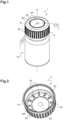
- the sealing cap 2 is used as an inner part of a child-resistant and tamper-evident closure 1, configured to close an opening 12 of a container 10. More precisely, the inner sealing cap 2 of the closure 1 is configured to be screwed onto the container 10, the opening 12 of which is provided with an external thread 14 as visible for example in Figure 8 .
- the shape of the container 10 shown in the figures only serves as an example, it being understood that the container 10 can have any shape, as long as it is provided with an opening surrounded, either externally as shown in the figures, or else internally, by a thread 14 on which the inner sealing cap 2 of the closure 1 can be screwed.
- the container is provided with a neck portion.
- the container in the shape of a bottle with a relatively narrow neck, or in the shape of a straight cylinder.
- annular container thread which may be a continuous thread or an interrupted thread.
- the closure 1 comprises two caps which are nested inside each other.
- the outer cap 6 which comprises a top wall 61 and a sidewall 63.
- the sidewall 63 can be provided with suitable means to increase the grip for a user.
- a plurality of ribs are provided on the sidewall 63, extending axially in the direction of a main axis X of the closure.
- the top wall 61 comprises a tamper-evident member 64, which is connected to a surrounding region 65 by a frangible structure 66.
- the frangible structure comprises four distinct frangible bridges 66 regularly distributed around the periphery of the tamper-evident member 64.
- the frangible structure 66 may be formed by a material of reduced thickness fully surrounding the tamper-evident member 64.
- the geometry of the outer cap 6 represented in Figure 1 only serves as an example, and other geometries are also possible.
- the inner sealing cap 2 comprises a cap body 3 with a top wall 31 and a sidewall 33.
- the top wall 31 is provided with a protruding element 36.
- the protruding element 36 has a geometry which corresponds to the geometry of the tamper-evident member 64 being part of the top wall 61 of the outer cap 6.
- the protruding element 36 is configured to remove the tamper-evident member 64 by breaking the frangible bridges 66 between the tamper-evident member 64 and the surrounding region 65, upon axial displacement of the outer cap 6 toward the cap body 3 of the inner sealing cap 2 in the direction of the main axis X.
- the rupture of the frangible bridges 66 results from an axial stretching stress applied thereto in the direction of the main axis X.
- the cap body 3 of the inner sealing cap 2 is provided with an inner cap thread 34 which is configured to cooperate with the container thread 14 of the container 10.
- the closure 1 can be screwed onto the neck of the container 10 by rotation in a screwing direction R 1 which, in this example, is a clockwise direction.
- the inner sealing cap 2 comprises a receptacle 4, which defines a chamber 40 for receiving an active material 8 capable of regulating the atmosphere in the container 10, in particular a desiccant and/or an oxygen scavenger.
- the chamber 40 is delimited by a bottom wall 41 and a sidewall 43, and is closed by a gas-permeable cover 48 which retains the active material 8 inside the chamber.
- the gas-permeable cover 48 is a cardboard held at its periphery by a thinner extension 45 of the sidewall 43 which has been crimped.
- the gas-permeable cover 48 may be a porous membrane secured to the distal end of the sidewall 43, e.g. by heat-sealing, ultrasonic welding, overmolding, etc.
- the receptacle 4 is held in a cavity 30 of the cap body 3 by a holding element 5, which is a third part of the inner sealing cap 2 in addition to the cap body 3 and the receptacle 4.
- the holding element 5 is a multifunction component including several parts with dedicated functions.
- the holding element 5 comprises a central part playing the role of a sealing member 51, configured to provide a gas-tight seal between the cap body 3 and the container 10 when the inner sealing cap 2 is in a configuration fixed on the container 10.
- the sealing member 51 comprises a flat sealing surface 52 forming an inner surface of the inner sealing cap 2 positioned transversally to the main axis X, so as to provide a gas-tight seal between the inner sealing cap 2 and an upper surface 16 of the container opening 12.
- a flat sealing surface 52 positioned transversally to the main axis X makes it possible to adapt to a wide range of containers.
- the holding element 5 also comprises, regularly distributed over the circumference of the sealing member 51, a plurality of outer tabs 53 and a plurality of inner flaps 54.
- Each outer tab 53 forms a connecting part of the holding element 5 configured to be received in a corresponding inner groove 39 of the cap body, in such a way that the holding element 5 is maintained relative to the cap body 3 with possibility of movement in the direction of the main axis X.
- Each inner flap 54 forms a movable part of the holding element 5, configured to move relative to the connecting tabs 53 under the action of a pushing force P applied by the cap body 3 upon fixing the inner sealing cap 2 on the container 10.
- each inner groove 39 of the cap body is connected to an aperture 39'. Thanks to this structure, it is possible to obtain the cap body 3 easily by injection molding, the risks of damage during release of the part from the injection mold being low because the inner grooves 39 can be obtained without molding undercuts.
- the selection of the constitutive material(s) of the holding element 5 is key to ensure that the various functions of this component are carried out in a reliable and lasting manner, including the sealing function performed by the sealing member 51 at the interface between the cap body 3 and the container 10, the anchoring function relative to the cap body 3 performed by the outer connecting tabs 53, the holding and releasing functions of the receptacle 4 relative to the cap body 3 performed by the inner movable flaps 54.
- the whole of the holding element may be made of a thermoplastic elastomer (TPE), preferably a thermoplastic vulcanizate (TPV), having a Shore A hardness and a thickness selected to ensure all of the above functions.
- each part 51, 53, 54 of the holding element may be made of a specific material specially adapted to its function.
- the whole of the holding element may be made of a thermoplastic vulcanizate (TPV) having a Shore A hardness of 60 and a thickness of 1.5 mm.
- TPV thermoplastic vulcanizate
- a non-limitative example of a suitable material for the holding element 5 is a thermoplastic vulcanizate selected in the TPV - Elastron ® V Series designed for use in medical applications, which are based on mixtures of EPDM and PP, e.g., the products Elastron ® P.V101, such as Elastron ® P.V101.A60.B having a Shore A hardness of 60 measured according to standard ASTM D2240.
- the inner sealing cap 2 is configured to expose the gas-permeable wall 48 of the receptacle to the exterior of the cavity 30 only when the inner sealing cap 2 is fixed on the container 10, making it possible to use the regulation capacity of the active material 8 only when the container 10 is gas-tightly closed by the inner sealing cap 2.
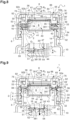
- the holding element 5 is configured to hold the receptacle 4 relative to the cap body 3 in such a way that, before the inner sealing cap 2 is fixed on the container 10, the receptacle 4 is held by the inner flaps 54 in a first position, visible in Figure 8 , in which the gas-permeable wall 48 is gas-tightly enclosed in the cavity 30.
- the cap body 3 and the receptacle 4 comprise complementary annular sealing surfaces 37 and 47 of frustoconical shape, respectively defined by a flared edge 30' of the cavity 30 and by an outer peripheral shoulder 44 of the receptacle 4.
- the frustoconical sealing surfaces 37 and 47 are in sealing contact when the receptacle 4 is in the first position.
- the holding element 5 is also configured to hold the receptacle 4 relative to the cap body 3 in such a way that, when the inner sealing cap 2 is fixed on the container 10, the receptacle 4 is released by the inner flaps 54 to a second position, visible in Figure 9 , in which the gas-permeable wall 48 is exposed to the atmosphere in the container 10.
- the cap body 3 comprises an annular pressure rib 35 provided on a transverse wall 38 of the cap body arranged transversely to the main axis X.
- the pressure rib 35 is positioned facing the part of the holding element 5 corresponding to the inner flaps 54 and is designed to apply a pushing force P on the inner flaps 54 when the inner sealing cap 2 is in the process of being fixed on the container 10 and the surface 52 of the sealing member 51 comes in sealing contact with the container 10. Under the action of the pushing force P, the inner flaps 54 move relative to the connecting tabs 53 by bending at the level of the pressure rib 35, thus releasing the receptacle 4 from the first position to the second position.
- the degree of bending movement of the inner flaps 54 relative to the connecting tabs 53 at the level of the pressure rib 35 depends on the height of the pressure rib 35 in the direction of the main axis X and on the radial position of the pressure rib 35.
- the height h 1 of the pressure rib 35 in the direction of the main axis is selected so that, in the second position, the receptacle 4 is still held with respect to the cap body 3 by the inner flaps 54.
- the inner flaps 54 move the receptacle 4 relative to the cap body 3 back from the second position to the first position because the pushing force P applied by the pressure rib 35 on the inner flaps 54 is released.
- the receptacle 4 is thus axially movable relative to the cap body 3 in the direction of the main axis X between the first position and the second position, the movement being driven by the inner flaps 54 of the holding element as a function of the state of the inner sealing cap 2 relative to the container 10, i.e., either fixed on or removed from the container.
- the transverse wall 38 of the cap body may also be provided with an annular groove 381 facing the part of the holding element 5 corresponding to the sealing member 51 and defining a gap G 1 in the direction of the main axis X between the cap body and a bottom of the inner grooves 39 receiving the outer connecting tabs 53.
- the presence of the annular groove 381 gives more clearance for the holding element 5 to deform and facilitates the bending movement of the inner flaps 54 relative to the outer connecting tabs 53 under the effect of the pushing force P.
- the pushing force P is applied by the pressure rib 35, it being understood that the inner edge of the annular groove 381 closest to the pressure rib 35 also applies a pressure force P on the holding element 5.
- the pressure rib 35 may be omitted and the inner edge of the annular groove 381 may form the projecting element configured to apply a pushing force P on the holding element 5.
- the combination of the pressure rib 35 and the inner edge of the annular groove 381 to apply a pushing force ensures optimum bending deformation of the holding element 5.
- the pushing force P generates a bending of the inner flaps 54 of the holding element 5 when the sealing member 51 of the holding element 5 comes into contact with the upper surface 16 of the container opening 12 and is compressed between the transverse wall 38 of the cap body and the upper surface 16 of the container opening.
- the sidewall 63 of the outer cap 6 comprises a radially inwardly extending bead 62 which, in the mounted state of the outer cap 6 on the inner sealing cap 2, forms a positive lock with a radially outwardly extending flange 32 provided on the sidewall 33 of the cap body 3.
- the inner bead 62 and the outer flange 32 cooperate in a such a way as to firmly hold the outer cap 6 on the inner sealing cap 2, so that it can no longer be removed from the inner sealing cap 2.
- the closure 1 also comprises a child-resistant engagement mechanism between the outer cap 6 and the inner sealing cap 2.
- the outer cap 6 includes, on that side of the top wall 61 which, in the mounted state, faces the top wall 31 of the cap body 3, a plurality of radial ribs 76 regularly distributed on the surrounding region 65 and configured to cooperate with corresponding wedge-shaped elements 92 with beveled inclined surface provided on the top wall 31 of the inner sealing cap 2, between the protruding element 36 and the apertures 39'.
- the initial mounting configuration of the closure 1, suitable for the initial mounting of the closure on a container 10 is such that the radial ribs 76 are in contact with straight edges 92a of the wedge-shaped elements 92, with possibility of axial movement of the radial ribs 76 in the interspace between the wedge-shaped elements 92 in the direction of the main axis X, whereas the tamper-evident member 64 rests on the protruding element 36.
- the tamper-evident member 64 is configured to be detached from the surrounding region 65 upon application on the outer cap 6 of an axial pushing force F in the direction of the main axis X, so that the protruding element 36 is displaced in pushing abutment against the tamper-evident member 64, thus breaking the frangible bridges 66, while at the same time the radial ribs 76 are displaced in the interspace between the wedge-shaped elements 92 toward slanted edges 92b of the wedge-shaped elements 92.
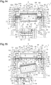
- An opening of the closure 1 requires that the radial ribs 76 of the outer cap 6 are brought in engagement with the slanted edges 92b of the wedge-shaped elements 92 of the inner sealing cap 2, which is only possible after the outer cap 6 has been axially displaced toward the inner sealing cap 2, in particular under the action of an axial pushing force F applied on the top wall 61 in the direction of the main axis X, as shown in Figure 10 . More precisely, under the action of the axial force F applied on the surrounding region 65, the outer cap 6 is displaced axially toward the inner sealing cap 2, and the tamper-evident member 64 is detached from the surrounding region 65 under the pressure exerted by the protruding element 36.
- the mounting (or closing) of the closure 1 onto a container is easy to achieve and only requires a simple rotational movement of the outer cap 6 in the direction of screwing R 1
- the opening of the closure 1 requires a complex operation starting with an axial displacement of the outer cap 6 toward the inner sealing cap 2 under an axial pressure force F in the direction of the main axis X, followed by a rotational movement in the direction of unscrewing R 2 while maintaining the axial pressure force F.
- Such complex operation establishes a highly effective child resistance of the closure 1.
- Figures 12 and 13 show a variant of a receptacle suitable for the inner sealing cap 2 of the first embodiment.
- the receptacle 104 comprises on its outer surface a plurality of notches 142 which are regularly distributed over the sidewall 143 and which extend between the outer peripheral shoulder 144 and the extension 145.
- the notches 142 form passages promoting gas exchange between the active material 8 inside the receptacle 104 and the atmosphere in the container 10.
- the presence of such gas passages defined by the notches 142 is all the more important as the clearance resulting from the opening of the inner flaps 54 in the second position is narrow.
- the receptacle 104 has notches 142 extending substantially parallel to the main axis X.
- the notches 142 of the receptacle may be oriented transversally to the main axis X.
- the notches 142 of the receptacle may be oriented helically around the main axis X or according to any other orientation allowing to create complex and/or tortuous passages. In this way, the notches 142 can be used to avoid leaks of particles of active material 8 out of the receptacle, in addition to promoting gas exchange between the active material 8 and the atmosphere in the container 10.
- the notches 142 of the receptacle may be designed to create passages so complex and/or tortuous that the cardboard 148 can be omitted, the active material 8 then being kept in the chamber 140 of the receptacle and the cavity 30 of the cap body thanks to the impossibility for the active material to exit the cavity 30 through the complex and/or tortuous passages defined by the notches 142.
- the closure 1 of the second embodiment differs from the first embodiment in that the structures of the cap body 3 and the holding element 5 are configured to drop the receptacle 4 into the container 10 when the inner sealing cap 2 is fixed on the container 10.
- the degree of bending movement of the inner flaps 54 relative to the connecting tabs 53 is increased compared to the first embodiment, by providing the pressure rib 35 with a height h 2 in the direction of the main axis X higher than the height h 1 of the first embodiment.
- the degree of flexion of the inner flaps 54 can also be increased by adjusting the radial position of the pressure rib 35, in addition or as a replacement for the increase in the height h 2 of the pressure rib 35.
- the transverse wall 38 of the cap body 3 does not comprise any groove similar to the groove 381 of the first embodiment, because the height h 2 of the pressure rib 35 already provides sufficient clearance between the transverse wall 38 and the bottom of the inner grooves 39 for the holding element 5 to deform.
- the gap G 2 in the direction of the main axis X between the cap body 3 and a bottom of the inner grooves 39 receiving the outer connecting tabs 53 is equal to the height h 2 of the pressure rib 35.
- the constitutive materials of the closure and the container of the invention, as well as the active material received in the cavity of the closure for regulation of the atmosphere inside the container, are selected according to the intended use of the container.
- the cap body 3, the receptacle 4 and the outer cap 6 are advantageously manufactured by injection molding of suitable polymer material(s), which may be one and the same polymer material, or different polymer materials selected according to the intended function of each element, or even according to the intended function of each portion of each element.
- suitable polymers for the cap body 3, the receptacle 4 and the outer cap 6 include polyolefin-based polymers, in particular polyethylene or polypropylene.
- the cap body 3 and the receptacle 4 may be made of high-density polyethylene (HDPE), whereas the outer cap 6 may be made of polypropylene (PP) or polyoxymethylene (POM).
- Polypropylene (PP) and polyoxymethylene (POM) are polymer materials that are advantageous for the outer cap 6, especially as they are materials that are brittle enough to allow the rupture of the frangible structure 66, but they are also flexible materials.
- the constitutive material of the holding element 5 may also be a specific polymer, especially with a Young's coefficient lower than that of the cap body 3.
- the holding element 5 may be made of a thermoplastic elastomer (TPE), preferably a thermoplastic vulcanizate (TPV), having a Shore A hardness of between 30 and 80.
- TPVs include those based on a mixture of ethylene propylene diene monomer (EPDM) and polypropylene (PP).
- the invention provides a sealing cap suitable for different sizes of container openings which, when fixed onto a container, makes it possible to safely preserve sensitive products stored in the container, while increasing the in-use life cycle of the active material. In this way, the shelf life of products contained in the container can be precisely controlled, while maintaining low production costs.
- a closure comprising a sealing cap according to the invention and an outer cap also makes it possible to combine the three functions of being child-resistant, tamper-evident and providing active control of the atmosphere in a container. Because of its high safety, a container with a closure according to the invention is advantageously used for storing tablets or capsules containing a pharmaceutical composition; nutraceuticals; herbalism products; or diagnostic products.
- the pressure rib of the cap body may have different cross sections (e.g., rounded, triangular), different heights and different radial positions.
- the receptacle may still be held by the at least one holding element in the second position, or it may be totally dropped in the container in the second position.
- the sealing member and the at least one holding element may be independent components instead of being formed by one and the same multifunctional component as shown in the figures.
- the plurality of connecting tabs and movable flaps belonging to the same multifunctional component may also be replaced by connecting tabs and movable flaps belonging to discrete holding elements distributed over the circumference of the sealing cap, at the interface between the cap body and the receptacle.
- the sealing member between the cap body of the inner sealing cap and the container may have a frustoconical sealing surface, instead of flat sealing surface.
- the tamper-evident member may be a safety strip, instead of a tamper-evident disc as shown in the figures.
- the safety strip may be integral with one among the inner sealing cap and the outer cap, while being connected by a frangible structure to the other one among the inner sealing cap and the outer cap.
- the frangible structure may also comprise a continuous thinned portion of material, instead of a plurality of frangible bridges.
- the cap body of the inner sealing cap may be fixed on the container by other fixing means than screwing, e.g. the threads 14 and 34 may be replaced by clipping elements such as a bead on the container configured to be clipped in a corresponding groove of the first side wall of the cap body.
- the container may also comprise an internal thread on its inner surface, instead of an external thread on its outer surface as shown in the figures, with the cap thread being provided on the outer face of the first side wall of the cap body.
- the sealing member is independent from the at least one holding element and may for example be provided on the inner face of an external sealing skirt coming around the neck of the container so as to be pressed against the outer surface of the container upon screwing the cap thread onto the neck thread.
- the geometry, the number, and the arrangement of the coupling elements of the child-resistant engagement mechanism and mounting engagement mechanism may also be different from those described above. It is notably understood that the invention may be implemented with any type of child-resistant engagement mechanism, e.g., a "push-and-turn” child-resistant mechanism, a “squeeze-and-turn” child-resistant mechanism, a “push-and-squeeze-and-turn” child-resistant mechanism, as long as the removal of the tamper-evident member releases at least one degree of freedom of relative movement between the outer cap 6 and the inner sealing cap 2.
- the child-resistant mechanism may also comprise an elastic element, such as a spring arranged between the inner sealing cap and the outer cap, for automatically disengaging the coupling elements of the child-resistant mechanism, e.g., when the axial force F is released in the embodiments described above.
- the child-resistant and tamper-evident functions may also be directly integrated within the cap body 3, in cooperation with corresponding elements provided on the container, e.g., as disclosed in EP2842886A1 .
Landscapes
- Engineering & Computer Science (AREA)
- Mechanical Engineering (AREA)
- Closures For Containers (AREA)
Priority Applications (2)
| Application Number | Priority Date | Filing Date | Title |
|---|---|---|---|
| EP23201198.1A EP4534436A1 (fr) | 2023-10-02 | 2023-10-02 | Capuchon d'étanchéité avec un matériau actif |
| PCT/EP2024/077740 WO2025073760A1 (fr) | 2023-10-02 | 2024-10-02 | Capuchon d'étanchéité et fermeture le comprenant |
Applications Claiming Priority (1)
| Application Number | Priority Date | Filing Date | Title |
|---|---|---|---|
| EP23201198.1A EP4534436A1 (fr) | 2023-10-02 | 2023-10-02 | Capuchon d'étanchéité avec un matériau actif |
Publications (1)
| Publication Number | Publication Date |
|---|---|
| EP4534436A1 true EP4534436A1 (fr) | 2025-04-09 |
Family
ID=88237529
Family Applications (1)
| Application Number | Title | Priority Date | Filing Date |
|---|---|---|---|
| EP23201198.1A Pending EP4534436A1 (fr) | 2023-10-02 | 2023-10-02 | Capuchon d'étanchéité avec un matériau actif |
Country Status (2)
| Country | Link |
|---|---|
| EP (1) | EP4534436A1 (fr) |
| WO (1) | WO2025073760A1 (fr) |
Citations (4)
| Publication number | Priority date | Publication date | Assignee | Title |
|---|---|---|---|---|
| US2487620A (en) * | 1946-03-08 | 1949-11-08 | Waller Fred | Desiccator |
| EP2842886A1 (fr) | 2008-10-24 | 2015-03-04 | Clariant Production (France) S.A.S. | Capuchon vissé, corps de récipient et récipient |
| CN216187559U (zh) * | 2021-09-24 | 2022-04-05 | 塞纳医药包装材料(昆山)有限公司 | 一种防潮盖及防潮包装瓶 |
| US11498731B2 (en) * | 2016-06-22 | 2022-11-15 | Airnov, Inc. | Tamper-evident closure, container with such closure and its use |
-
2023
- 2023-10-02 EP EP23201198.1A patent/EP4534436A1/fr active Pending
-
2024
- 2024-10-02 WO PCT/EP2024/077740 patent/WO2025073760A1/fr active Pending
Patent Citations (4)
| Publication number | Priority date | Publication date | Assignee | Title |
|---|---|---|---|---|
| US2487620A (en) * | 1946-03-08 | 1949-11-08 | Waller Fred | Desiccator |
| EP2842886A1 (fr) | 2008-10-24 | 2015-03-04 | Clariant Production (France) S.A.S. | Capuchon vissé, corps de récipient et récipient |
| US11498731B2 (en) * | 2016-06-22 | 2022-11-15 | Airnov, Inc. | Tamper-evident closure, container with such closure and its use |
| CN216187559U (zh) * | 2021-09-24 | 2022-04-05 | 塞纳医药包装材料(昆山)有限公司 | 一种防潮盖及防潮包装瓶 |
Also Published As
| Publication number | Publication date |
|---|---|
| WO2025073760A1 (fr) | 2025-04-10 |
Similar Documents
| Publication | Publication Date | Title |
|---|---|---|
| US12006110B2 (en) | Tamper-evident closure | |
| US11801989B2 (en) | Container for medical and/or pharmaceutical products | |
| US10518941B2 (en) | Dispensing closure | |
| WO2005074571A2 (fr) | Joint a levre souple pour ensemble recipient et couvercle integre | |
| EP3016628B1 (fr) | Capuchon de flacon de substance parentérale | |
| EP3728073B1 (fr) | Dispositif limiteur de débit et bouchon pour un récipient le comprenant | |
| US20200399030A1 (en) | Closure for a container | |
| CN112236118B (zh) | 带有间隙的用于医疗产品和/或药物产品的容器 | |
| CN100564179C (zh) | 防止儿童拆卸的掀顶式容器组件及掀顶式封盖 | |
| CN118251298A (zh) | 分配闭合件 | |
| EP4534436A1 (fr) | Capuchon d'étanchéité avec un matériau actif | |
| US20250019130A1 (en) | Screw-top cap for container, and method of using and making same | |
| US20250361064A1 (en) | Tamper-evident closure | |
| CN1079072C (zh) | 用合成树脂制成的防盗盖 | |
| US20260021944A1 (en) | Sealing cap and closure comprising the same | |
| US12269652B2 (en) | Dispensing closure | |
| US12397972B1 (en) | Dispensing closure | |
| HK1056350B (en) | Package with multiple chambers and valves |
Legal Events
| Date | Code | Title | Description |
|---|---|---|---|
| PUAI | Public reference made under article 153(3) epc to a published international application that has entered the european phase |
Free format text: ORIGINAL CODE: 0009012 |
|
| STAA | Information on the status of an ep patent application or granted ep patent |
Free format text: STATUS: THE APPLICATION HAS BEEN PUBLISHED |
|
| AK | Designated contracting states |
Kind code of ref document: A1 Designated state(s): AL AT BE BG CH CY CZ DE DK EE ES FI FR GB GR HR HU IE IS IT LI LT LU LV MC ME MK MT NL NO PL PT RO RS SE SI SK SM TR |
|
| STAA | Information on the status of an ep patent application or granted ep patent |
Free format text: STATUS: REQUEST FOR EXAMINATION WAS MADE |
|
| 17P | Request for examination filed |
Effective date: 20251009 |
|
| GRAP | Despatch of communication of intention to grant a patent |
Free format text: ORIGINAL CODE: EPIDOSNIGR1 |
|
| STAA | Information on the status of an ep patent application or granted ep patent |
Free format text: STATUS: GRANT OF PATENT IS INTENDED |