EP4534466A2 - Unité de déclenchement destinée à actionner un dispositif de freinage d'ascenseur - Google Patents
Unité de déclenchement destinée à actionner un dispositif de freinage d'ascenseur Download PDFInfo
- Publication number
- EP4534466A2 EP4534466A2 EP25158860.4A EP25158860A EP4534466A2 EP 4534466 A2 EP4534466 A2 EP 4534466A2 EP 25158860 A EP25158860 A EP 25158860A EP 4534466 A2 EP4534466 A2 EP 4534466A2
- Authority
- EP
- European Patent Office
- Prior art keywords
- release
- elevator
- roller
- clamping
- guide rail
- Prior art date
- Legal status (The legal status is an assumption and is not a legal conclusion. Google has not performed a legal analysis and makes no representation as to the accuracy of the status listed.)
- Granted
Links
Images


Classifications
-
- B—PERFORMING OPERATIONS; TRANSPORTING
- B66—HOISTING; LIFTING; HAULING
- B66B—ELEVATORS; ESCALATORS OR MOVING WALKWAYS
- B66B5/00—Applications of checking, fault-correcting, or safety devices in elevators
- B66B5/02—Applications of checking, fault-correcting, or safety devices in elevators responsive to abnormal operating conditions
- B66B5/16—Braking or catch devices operating between cars, cages, or skips and fixed guide elements or surfaces in hoistway or well
- B66B5/18—Braking or catch devices operating between cars, cages, or skips and fixed guide elements or surfaces in hoistway or well and applying frictional retarding forces
Definitions
- the invention relates to a triggering unit for actuating an elevator braking device according to the preamble of claim 1.
- Elevators are typically equipped with an elevator brake that slows or catches the car in the event of an excessively high travel speed. Possible causes of excessive acceleration of the car include a malfunction in the control system of a drive or its brake, or a broken cable.
- the elevator brake device can be triggered in various ways.
- the braking device In classic, purely mechanical triggering units, the braking device is usually activated by an overspeed governor mounted in the shaft. In this respect, the WO 97/31852 be referred to.
- a self-contained governor rope is installed in the elevator shaft, which is deflected by the overspeed governor and a tension pulley.
- the governor rope is connected at one point to the brake mechanism of the elevator car or the brake element of the brake mechanism. Accordingly, it is entrained by the elevator car when it moves. An unacceptably high travel speed then causes the overspeed governor to decelerate the governor rope. Since the governor rope moves more slowly in the elevator shaft than the elevator car and the attached brake element, the governor rope exerts a tensile force on the brake element. This activates the brake mechanism.
- a typical elevator braking device equipped with an electromagnetic trip unit is used, for example, in WO 2006/077243 A1 It shows a braking device for an elevator car, the braking element of which is held in an active position by a retaining element as long as the elevator car is not to be braked.
- the retaining element is an electromagnet that attracts the braking element, designed as a brake roller, and thus prevents it from coming into contact with the guide rail of the elevator.
- the electromagnet is switched off and the braking element is pressed towards the guide rail by a compression spring.
- the brake roller rolls along the guide rail and runs into a wedge gap between the guide rail and a pressure element, which is also part of the braking system.
- the brake roller equipped with a friction surface, decelerates the elevator car.
- the electromagnet is activated. This moves the braking element, counteracting the action of the compression spring, back into a position where there is no longer any contact with the guide rail.
- the electromagnet Before the electromagnet can engage the braking element, however, it must be pushed out of the wedge gap. To do this, the elevator car is usually moved back a little.
- Such electrically triggered elevator braking devices have the advantage over traditional designs triggered by the overspeed governor rope that they can also be used, for example, to prevent what is known as unintended car movement (UCM).
- UCM stands for "unintended car movement,” i.e., the danger that an elevator car begins to creep away from its stopping position in front of the landing door during an increase in its rated load, e.g., due to several passengers boarding at a stop.
- Elevator braking device requires recertification.
- the triggering unit does not transmit any actuating force to the elevator brake device, so that it remains untriggered.
- the rocker is mounted on the trigger base in such a way that it can rotate around a fixed axis of rotation relative to the trigger base.
- the rocker typically has two overlapping, essentially opposite sections, with the axis of rotation located between them.
- the two sections of the rocker are referred to as rocker arms.
- the electromagnet acts against one of the rocker arms, preventing the other arm from rotating toward the guide rail.
- the electromagnet overcomes the spring force of the tension spring.
- the tension spring exerts a force—preferably a compressive force—on the rocker arm not in contact with the electromagnet, toward the guide rail.
- the guide rod which forms part of the slide guide, is mounted directly on the trigger body. Usually, it is rigid. This ensures particularly precise guidance.
- the braking or safety gear brakes the car usually by wedging it with the elevator guide rails, or catches the car as soon as it has been initially activated by the triggering unit and then independently takes over the braking or safety gear regime.
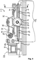
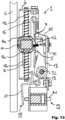
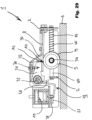
- the elevator brake device 23 is attached to the car frame during operation of the elevator and engages with its pressure body 27 one of the guide rails 6 in the elevator shaft - just as the Fig. 3 visualized.
- the elevator brake device 23 therefore moves with the elevator car in its direction of travel.
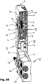
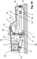
- Fig. 1 the elevator brake device 23 is in the non-triggered position. This means that the braking element 25 is not in contact with the guide rail 6. In order to achieve a braking effect, the braking element 25 must be moved against the action of the return spring 26 into a wedge gap between the pressure body 27 and the guide rail 6. As soon as the braking element 25 is in the wedge gap and the car continues to move along the guide rail 6, the braking element 25, which is designed as a circular cylinder, rolls along the guide rail 6 and automatically retracts itself further into the wedge gap. The direction of movement of the The braking element 25 runs counter to the direction of travel of the car. Since the pressure body 27 is designed such that a wedge gap exists in both directions along the guide rail 6, this is possible both during upward and downward travel of the car along the guide rail 6.
- the trigger unit 1 therefore serves the purpose of moving the braking element 25 of the elevator braking device 23 into the wedge gap in the event of an excessively high speed or acceleration.
- the coupling element 22 is connected to the release unit 1 via its clamping roller 5.
- the coupling element 22 is connected to the elevator brake device 23 via the brake element 25 of the elevator brake device 23, see Fig. 1 .
- the coupling member 22 is formed by a bar, preferably made of steel. At one end, facing the trigger unit 1, the coupling member 22 is preferably provided with an elongated hole 17, as shown, for example, in Fig. 1 shows.
- the bolt 34 protrudes through the elongated hole 17 of the coupling link 22.
- the bolt 34 is connected to the clamping roller 5 at its end facing away from the coupling link 22 in such a way that it follows a translational movement of the clamping roller 5 parallel to the guide rail 6 and cannot slip in the axial direction.
- the retaining ring 35 is optionally provided on the bolt 34.
- the bolt 34 arranged coaxially to the clamping roller 5 is located exactly in or substantially in the middle of the elongated hole 17, cf.
- Fig. 1 The center of the slot 17 indicates the area of the slot 17 from which Direction parallel to the guide rail 6 the distance to both ends of the elongated hole 17 is the same.
- the coupling member 22 is rotatably mounted on the braking element 25 of the elevator braking device 23. This means that the coupling member 22 and the braking element 25 can rotate relative to each other, with the longitudinal axis of the braking element 25, which is designed here as a circular cylinder, serving as the axis of rotation. This has the advantage that no tension occurs between the coupling member 22 and the braking element 25 when the braking element 25 is transferred into the braking state by the coupling member 22.
- the coupling element 22 In order to activate the braking device 23, the coupling element 22 must be forced by the triggering unit 1 during the travel of the elevator car along the guide rail 6 into a translational movement relative to the elevator braking device 23, which moves the braking element 25 into the wedge gap or (in the case of bidirectional operation) into one of the wedge gaps between the guide rail 6 and the pressure body 27 of the elevator braking device 23.
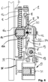
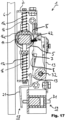
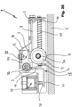
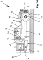
- the release unit 1 according to the invention is shown in a side view on a guide rail 6 of an elevator without the elevator brake device 23 being shown again, in the non-triggered state as it occurs during normal travel.
- the rocker 18 is formed by a bar, ideally bent several times, as it is usually ductile.
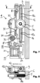
- the rocker 18 is, for example, connected via a pivot bearing 32 in accordance with. Fig. 4 attached to the trigger base body 2 of the trigger unit 1.
- the trigger clamping surface 7 is located on the rocker arm 24 of the rocker 18 facing away from the electromagnet 19. With its help, when activated, it can press directly onto the clamping roller in order to move it against the guide rail.
- the electromagnet 19 thus has the task of counteracting the spring force of the torsion spring 13 via the rocker 18, thereby preventing a pivoting movement of the release clamping surface 7 in the direction of the guide rail 6.
- the force required by the electromagnet 19 to overcome the spring force of the torsion spring 13 can thus be adjusted, at least from a design perspective, via the ratio of the lengths of the rocker arms 21 and 24.
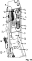
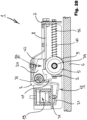
- the trigger base body 2 carries, usually rigidly, the guide rod 15a or 40 of the roller carriage guide 15.
- Two spring elements 16, here preferably in the form of helical compression springs, are threaded onto the guide rod 15a or 40. They are supported on both sides against the guide carriage 14 by means of their preferred spring plates 16a.
- the guide carriage can move in and against the direction of travel on the guide rod 15a or 40 by compressing one or the other spring element 16.
- the roller carriage guide essentially has the task of ensuring that the guide carriage always returns to its central position, which it assumes when not triggered.
- the guide carriage can then be guided on the guide rod 15a or 40 so as to be rotatable around the guide rod.
- it can also be designed in such a way that the guide rod 15a or 40 provides it with reinforced guidance, for example guiding it in a torsion-proof manner or with reduced torsional play.
- the guide carriage 14 itself has a transverse guide 14a, here preferably in the form of a transverse guide element, usually designed as a bent sheet metal part. It guides the bolt 34, on which the clamping roller 5 and the eccentric roller 9 are arranged coaxially and via which the coupling to the coupling link or connecting rod 22 is also established.
- the guide is such that the bolt can be moved up and down in such a way that the clamping roller, including the eccentric roller, can be moved toward or away from the guide rail.
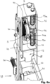
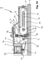
- the deenergized electromagnet 19 no longer applies any pressure to the plunger 31, so that the rocker arm 21 is no longer loaded by the plunger 31.
- the leg spring thus rotates the rocker arm, in this case clockwise, together with the release clamping surface 7, which is usually formed directly by it.
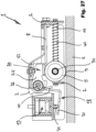
- the eccentric roller 9 is designed as a circular cylinder or circular cylinder section, ideally surrounded by a friction lining. As already mentioned, the eccentric roller 9 is rotatably mounted on the common pin 34. The rotational axis of the eccentric roller 9 is not coaxial with its own longitudinal axis. When the car continues to move along the guide rail 6 after the eccentric roller has first come into contact with the guide rail, the eccentric roller 9 rolls along the guide rail 6, thereby reducing its restrictive diameter.
- the safety gear not be triggered if only a millimeter-long movement of the elevator car is recorded. Because if the clamping roller 5 actually rolls along the guide rail 6 and moves the braking element 25 of the braking device 23 into the wedge gap via the coupling link 22, the braking element 25 would have to be moved out of the wedge gap to restart the elevator. However, this is only possible by moving the elevator car back a little.
- the clamping roller 5 moves out of the gap between the release clamping surface 7 and the guide rail 6 and into the gap between the upper main clamping surface 8 and the Guide rail 6.
- the release clamping surface 7 is an integral part of the rocker 18.
- the gap between the main clamping surface 8 and the guide rail 6 is subjected to a significantly stronger compressive force in the direction of the guide rail 6. This is achieved by the main clamping surfaces 8 being supported by a spring 30. It is also conceivable for the main clamping surfaces 8 to be an integral part of the spring 30.
- the spring 30 is, for example, a steel sheet made of spring steel, which has a U-shaped cross-section with two symmetrical legs parallel to the main clamping surfaces 8. The spring 30 is usually screwed directly to the release base body 2 and is supported on it.
- the elevator car In order to move the elevator brake device 23 and at the same time the triggering unit 1 back to the non-triggered state, the elevator car must be moved in the opposite direction to the previous direction of travel.
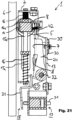
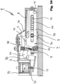
- a second embodiment is described by the Figures 23 to 25 shown.
- This second embodiment corresponds to the first embodiment in terms of its principle and functionality. Therefore, what is stated there also applies to the second embodiment, unless expressly stated otherwise by the differences described below.
- the rocker 18 with its second rocker arm 24 is on the side of the roller cage facing away from the guide rail 6 figs 4
- the electromagnet 19 presses with its plunger 31 on the first rocker arm 21 and thereby pivots the rocker 18 so that it fig 4 away from the guide rail - so in the picture below, which shows the Figure 24 counterclockwise.
- the electromagnet 19 is no longer energized, the force exerted by the plunger 31 is eliminated.
- the preload of the spring elements 13 on the slide rods 12 can have the effect that the roller cage fig 4 towards the guide rail 6.
- a further advantageous or inventive embodiment (AF) is as follows.
- AF 1 Release unit 1 for actuating an elevator brake device 23 with a release base body 2 that can be mounted on the elevator car, a release 20, and a coupling member 22, via which the release unit 1 can be connected to an elevator brake device 23, wherein the release unit 1 is preferably designed as a completely separate assembly from said elevator brake device 23, which, in the properly mounted state, is connected to the elevator brake device 23 exclusively via the coupling member 22, wherein the release unit 1 comprises a release clamping surface 7 that can be actuated by a release 20, which, after release, moves together with a clamping roller 5 transversely to the elevator travel direction in the direction of the elevator guide rail 6 assigned to it, until the clamping roller 5 is clamped between the release clamping surface 7 and the elevator rail 6 and rolls between the release clamping surface 7 and the elevator rail 6, characterized in that preferably directly next to or coaxial with the clamping roller 5, at least one eccentric roller 9 is provided, which is designed and mounted eccentrically in such a way that it comes into contact with the guide rail 6 earlier than the clamping roller 5
- AF 4 Release unit 1 according to one of the preceding AFs in conjunction with AF 2, characterized in that the guide carriage 14 forms an anchoring point - preferably located on an arm projecting from it in the direction away from the guide rail 6 - for a return spring 10, the other end of which is anchored to the eccentric roller 9 and which pulls the eccentric roller 9 into its ready position.
- AF 5 Release unit 1 according to one of the preceding AFs, characterized in that the guide rod 15a is mounted directly on the release base body 2.
- AF 7 Release unit 1 according to one of the preceding AFs, characterized in that a main clamping surface 8 adjoins the release clamping surface 7 on both sides, seen in both directions of travel, which is anchored separately from the release clamping surface 7 on the release base body 2 and wherein the release clamping surface 7 and the main clamping surfaces 8 are arranged and designed such that the clamping roller 5 rolls over each end of the release clamping surface 7 into the gap between a main clamping surface 8 and the guide rail 6, regardless of whether an upward or downward travel is currently being carried out.
Landscapes
- Engineering & Computer Science (AREA)
- Mechanical Engineering (AREA)
- Maintenance And Inspection Apparatuses For Elevators (AREA)
Applications Claiming Priority (3)
| Application Number | Priority Date | Filing Date | Title |
|---|---|---|---|
| DE202022100182.0U DE202022100182U1 (de) | 2022-01-13 | 2022-01-13 | Auslöseeinheit zum Betätigen einer Aufzugbremsvorrichtung |
| EP22843211.8A EP4463410B1 (fr) | 2022-01-13 | 2022-12-20 | Unité de déclenchement destinée à actionner un dispositif de freinage d'ascenseur |
| PCT/EP2022/087065 WO2023134982A1 (fr) | 2022-01-13 | 2022-12-20 | Unité de déclenchement destinée à actionner un dispositif de freinage d'ascenseur |
Related Parent Applications (2)
| Application Number | Title | Priority Date | Filing Date |
|---|---|---|---|
| EP22843211.8A Division-Into EP4463410B1 (fr) | 2022-01-13 | 2022-12-20 | Unité de déclenchement destinée à actionner un dispositif de freinage d'ascenseur |
| EP22843211.8A Division EP4463410B1 (fr) | 2022-01-13 | 2022-12-20 | Unité de déclenchement destinée à actionner un dispositif de freinage d'ascenseur |
Publications (3)
| Publication Number | Publication Date |
|---|---|
| EP4534466A2 true EP4534466A2 (fr) | 2025-04-09 |
| EP4534466A3 EP4534466A3 (fr) | 2025-06-18 |
| EP4534466B1 EP4534466B1 (fr) | 2026-02-18 |
Family
ID=80221946
Family Applications (2)
| Application Number | Title | Priority Date | Filing Date |
|---|---|---|---|
| EP22843211.8A Active EP4463410B1 (fr) | 2022-01-13 | 2022-12-20 | Unité de déclenchement destinée à actionner un dispositif de freinage d'ascenseur |
| EP25158860.4A Active EP4534466B1 (fr) | 2022-01-13 | 2022-12-20 | Unité de déclenchement destinée à actionner un dispositif de freinage d'ascenseur |
Family Applications Before (1)
| Application Number | Title | Priority Date | Filing Date |
|---|---|---|---|
| EP22843211.8A Active EP4463410B1 (fr) | 2022-01-13 | 2022-12-20 | Unité de déclenchement destinée à actionner un dispositif de freinage d'ascenseur |
Country Status (4)
| Country | Link |
|---|---|
| EP (2) | EP4463410B1 (fr) |
| CN (1) | CN118632815A (fr) |
| DE (1) | DE202022100182U1 (fr) |
| WO (1) | WO2023134982A1 (fr) |
Families Citing this family (1)
| Publication number | Priority date | Publication date | Assignee | Title |
|---|---|---|---|---|
| US20250145413A1 (en) * | 2022-02-04 | 2025-05-08 | Cobianchi Liftteile Ag | Brake catching device |
Citations (3)
| Publication number | Priority date | Publication date | Assignee | Title |
|---|---|---|---|---|
| WO1997031852A1 (fr) | 1996-03-01 | 1997-09-04 | Cobianchi Liftteile Ag | Parachute a prise instantanee et machoire de frein, notamment pour cabines d'ascenseur |
| WO2006077243A1 (fr) | 2005-01-21 | 2006-07-27 | Wittur Ag | Dispositif de freinage ou d'arret d'une cabine d'ascenseur |
| DE202019105584U1 (de) | 2019-10-10 | 2019-10-22 | Wittur Holding Gmbh | Auslöseeinheit zum Betätigen einer Aufzugbremsvorrichtung |
Family Cites Families (3)
| Publication number | Priority date | Publication date | Assignee | Title |
|---|---|---|---|---|
| DE102013111385A1 (de) * | 2013-10-15 | 2015-04-16 | Manfred Lienemann | Auslösevorrichtung einer Fangvorrichtung für eine Aufzugskabine einer Aufzugsanlage |
| EP4103502B1 (fr) * | 2020-02-14 | 2025-11-05 | Wittur Holding GmbH | Unité de déclenchement pour actionner un dispositif de freinage d'ascenseur |
| ES2921363B2 (es) * | 2021-02-16 | 2023-04-14 | Orona S Coop | Sistema de activación electromecánico para paracaídas de aparatos elevadores |
-
2022
- 2022-01-13 DE DE202022100182.0U patent/DE202022100182U1/de active Active
- 2022-12-20 EP EP22843211.8A patent/EP4463410B1/fr active Active
- 2022-12-20 CN CN202280088963.4A patent/CN118632815A/zh active Pending
- 2022-12-20 EP EP25158860.4A patent/EP4534466B1/fr active Active
- 2022-12-20 WO PCT/EP2022/087065 patent/WO2023134982A1/fr not_active Ceased
Patent Citations (4)
| Publication number | Priority date | Publication date | Assignee | Title |
|---|---|---|---|---|
| WO1997031852A1 (fr) | 1996-03-01 | 1997-09-04 | Cobianchi Liftteile Ag | Parachute a prise instantanee et machoire de frein, notamment pour cabines d'ascenseur |
| WO2006077243A1 (fr) | 2005-01-21 | 2006-07-27 | Wittur Ag | Dispositif de freinage ou d'arret d'une cabine d'ascenseur |
| EP1853504A1 (fr) | 2005-01-21 | 2007-11-14 | Wittur AG | Dispositif de freinage ou d'arret d'une cabine d'ascenseur |
| DE202019105584U1 (de) | 2019-10-10 | 2019-10-22 | Wittur Holding Gmbh | Auslöseeinheit zum Betätigen einer Aufzugbremsvorrichtung |
Also Published As
| Publication number | Publication date |
|---|---|
| CN118632815A (zh) | 2024-09-10 |
| EP4463410B1 (fr) | 2026-04-29 |
| EP4534466A3 (fr) | 2025-06-18 |
| DE202022100182U1 (de) | 2022-01-20 |
| WO2023134982A1 (fr) | 2023-07-20 |
| EP4463410A1 (fr) | 2024-11-20 |
| EP4534466B1 (fr) | 2026-02-18 |
Similar Documents
| Publication | Publication Date | Title |
|---|---|---|
| EP1733992B1 (fr) | Dispositif parachute | |
| EP4463409B1 (fr) | Unité de libération pour actionner un dispositif de frein d'ascenseur | |
| EP1902993B1 (fr) | Mécanisme de retour automatique pour un dispositif de freinage de type ABS | |
| EP2828188B1 (fr) | Dispositif antichute dans une installation d'ascenseur | |
| WO2021069739A1 (fr) | Unité de déclenchement destinée à actionner un dipsositif de freinage d'ascenseur | |
| WO2017125293A1 (fr) | Dispositif de freinage pour une cabine d'un système d'ascenseur | |
| EP3672898B1 (fr) | Entraînement auxiliaire pour dispositif de freinage de sécurité | |
| EP1853504B9 (fr) | Dispositif de freinage ou d'arret d'une cabine d'ascenseur | |
| EP3519339B1 (fr) | Actionneur électromécanique pour actionner un frein d'un système d'ascenseur | |
| EP1400476B1 (fr) | Parachute pour ascenseurs | |
| EP3693316B1 (fr) | Dispositif de sécurité d'ascenseur pourvu de déclencheur économe en énergie | |
| EP4077190B1 (fr) | Dispositif d'arrêt pour un ascenseur | |
| EP0899231B1 (fr) | Dispositif de freinage à double action | |
| EP4534466B1 (fr) | Unité de déclenchement destinée à actionner un dispositif de freinage d'ascenseur | |
| DE102007052280B4 (de) | Richtungsunabhängig ansprechender Geschwindigkeitsbegrenzer | |
| EP2043937B1 (fr) | Dispositif de freinage ou de blocage destiné à la sécurisation temporaire d'un espace de sécurité et similaires | |
| EP3927641B1 (fr) | Système de déclenchement pour un dispositif d'arrêt, installation d'ascenseur et procédé pour faire fonctionner une installation d'ascenseur | |
| EP3798174A1 (fr) | Dispositif de déclenchement pour un parachute |
Legal Events
| Date | Code | Title | Description |
|---|---|---|---|
| PUAI | Public reference made under article 153(3) epc to a published international application that has entered the european phase |
Free format text: ORIGINAL CODE: 0009012 |
|
| STAA | Information on the status of an ep patent application or granted ep patent |
Free format text: STATUS: THE APPLICATION HAS BEEN PUBLISHED |
|
| AC | Divisional application: reference to earlier application |
Ref document number: 4463410 Country of ref document: EP Kind code of ref document: P |
|
| AK | Designated contracting states |
Kind code of ref document: A2 Designated state(s): AL AT BE BG CH CY CZ DE DK EE ES FI FR GB GR HR HU IE IS IT LI LT LU LV MC ME MK MT NL NO PL PT RO RS SE SI SK SM TR |
|
| PUAL | Search report despatched |
Free format text: ORIGINAL CODE: 0009013 |
|
| AK | Designated contracting states |
Kind code of ref document: A3 Designated state(s): AL AT BE BG CH CY CZ DE DK EE ES FI FR GB GR HR HU IE IS IT LI LT LU LV MC ME MK MT NL NO PL PT RO RS SE SI SK SM TR |
|
| RIC1 | Information provided on ipc code assigned before grant |
Ipc: B66B 5/18 20060101AFI20250512BHEP |
|
| STAA | Information on the status of an ep patent application or granted ep patent |
Free format text: STATUS: REQUEST FOR EXAMINATION WAS MADE |
|
| 17P | Request for examination filed |
Effective date: 20250703 |
|
| GRAP | Despatch of communication of intention to grant a patent |
Free format text: ORIGINAL CODE: EPIDOSNIGR1 |
|
| STAA | Information on the status of an ep patent application or granted ep patent |
Free format text: STATUS: GRANT OF PATENT IS INTENDED |
|
| INTG | Intention to grant announced |
Effective date: 20251030 |
|
| GRAS | Grant fee paid |
Free format text: ORIGINAL CODE: EPIDOSNIGR3 |
|
| GRAA | (expected) grant |
Free format text: ORIGINAL CODE: 0009210 |
|
| STAA | Information on the status of an ep patent application or granted ep patent |
Free format text: STATUS: THE PATENT HAS BEEN GRANTED |
|
| AC | Divisional application: reference to earlier application |
Ref document number: 4463410 Country of ref document: EP Kind code of ref document: P |
|
| AK | Designated contracting states |
Kind code of ref document: B1 Designated state(s): AL AT BE BG CH CY CZ DE DK EE ES FI FR GB GR HR HU IE IS IT LI LT LU LV MC ME MK MT NL NO PL PT RO RS SE SI SK SM TR |
|
| REG | Reference to a national code |
Ref country code: CH Ref legal event code: F10 Free format text: ST27 STATUS EVENT CODE: U-0-0-F10-F00 (AS PROVIDED BY THE NATIONAL OFFICE) Effective date: 20260218 Ref country code: GB Ref legal event code: FG4D Free format text: NOT ENGLISH |
|
| REG | Reference to a national code |
Ref country code: DE Ref legal event code: R096 Ref document number: 502022007118 Country of ref document: DE |
|
| REG | Reference to a national code |
Ref country code: IE Ref legal event code: FG4D Free format text: LANGUAGE OF EP DOCUMENT: GERMAN |
|
| REG | Reference to a national code |
Ref country code: NL Ref legal event code: FP |