EP4534470A1 - Système d'exploitation - Google Patents
Système d'exploitation Download PDFInfo
- Publication number
- EP4534470A1 EP4534470A1 EP23202053.7A EP23202053A EP4534470A1 EP 4534470 A1 EP4534470 A1 EP 4534470A1 EP 23202053 A EP23202053 A EP 23202053A EP 4534470 A1 EP4534470 A1 EP 4534470A1
- Authority
- EP
- European Patent Office
- Prior art keywords
- crane
- vehicle
- logs
- loading
- fuel consumption
- Prior art date
- Legal status (The legal status is an assumption and is not a legal conclusion. Google has not performed a legal analysis and makes no representation as to the accuracy of the status listed.)
- Pending
Links
Images


Classifications
-
- B—PERFORMING OPERATIONS; TRANSPORTING
- B66—HOISTING; LIFTING; HAULING
- B66C—CRANES; LOAD-ENGAGING ELEMENTS OR DEVICES FOR CRANES, CAPSTANS, WINCHES, OR TACKLES
- B66C1/00—Load-engaging elements or devices attached to lifting or lowering gear of cranes or adapted for connection therewith for transmitting lifting forces to articles or groups of articles
- B66C1/10—Load-engaging elements or devices attached to lifting or lowering gear of cranes or adapted for connection therewith for transmitting lifting forces to articles or groups of articles by mechanical means
- B66C1/42—Gripping members engaging only the external or internal surfaces of the articles
- B66C1/58—Gripping members engaging only the external or internal surfaces of the articles and deforming the articles, e.g. by using gripping members such as tongs or grapples
- B66C1/585—Log grapples
-
- B—PERFORMING OPERATIONS; TRANSPORTING
- B66—HOISTING; LIFTING; HAULING
- B66C—CRANES; LOAD-ENGAGING ELEMENTS OR DEVICES FOR CRANES, CAPSTANS, WINCHES, OR TACKLES
- B66C1/00—Load-engaging elements or devices attached to lifting or lowering gear of cranes or adapted for connection therewith for transmitting lifting forces to articles or groups of articles
- B66C1/68—Load-engaging elements or devices attached to lifting or lowering gear of cranes or adapted for connection therewith for transmitting lifting forces to articles or groups of articles mounted on, or guided by, jibs
-
- B—PERFORMING OPERATIONS; TRANSPORTING
- B66—HOISTING; LIFTING; HAULING
- B66C—CRANES; LOAD-ENGAGING ELEMENTS OR DEVICES FOR CRANES, CAPSTANS, WINCHES, OR TACKLES
- B66C13/00—Other constructional features or details
- B66C13/18—Control systems or devices
- B66C13/46—Position indicators for suspended loads or for crane elements
-
- B—PERFORMING OPERATIONS; TRANSPORTING
- B66—HOISTING; LIFTING; HAULING
- B66C—CRANES; LOAD-ENGAGING ELEMENTS OR DEVICES FOR CRANES, CAPSTANS, WINCHES, OR TACKLES
- B66C13/00—Other constructional features or details
- B66C13/18—Control systems or devices
- B66C13/48—Automatic control of crane drives for producing a single or repeated working cycle; Program control
-
- B—PERFORMING OPERATIONS; TRANSPORTING
- B66—HOISTING; LIFTING; HAULING
- B66C—CRANES; LOAD-ENGAGING ELEMENTS OR DEVICES FOR CRANES, CAPSTANS, WINCHES, OR TACKLES
- B66C23/00—Cranes comprising essentially a beam, boom, or triangular structure acting as a cantilever and mounted for translatory of swinging movements in vertical or horizontal planes or a combination of such movements, e.g. jib-cranes, derricks, tower cranes
- B66C23/54—Cranes comprising essentially a beam, boom, or triangular structure acting as a cantilever and mounted for translatory of swinging movements in vertical or horizontal planes or a combination of such movements, e.g. jib-cranes, derricks, tower cranes with pneumatic or hydraulic motors, e.g. for actuating jib-cranes on tractors
Definitions
- Forestry machines especially vehicles must operate efficiently to address the workload and working costs.
- most of the work tasks is load and unloading of logs from the forestry area to a roadside area to be available for further transport.
- the process of loading and unloading involves a crane with a grapple tool reaching outwards to a log pile and repeatedly undergo the loading procedure to transfer a log pile to the vehicle or in a reverse manner to unload the log pile to a target area.
- the different tasks result in a certain fuel consumption or in a certain work time that depend on e.g., an outreach of the crane, the position of the vehicle, the load of the logs in the grapple tool, the speed of movement of the crane. As these parameters are subject to the local conditions, the efficiency of the vehicle is difficult to predict.
- the present invention aims to remedy those problems and to define a system and method which solves the above problems.
- the invention is a loading and unloading operation system adapted for use in a forestry vehicle, comprising a crane control unit and crane sensors, adapted to measure the turn angle of the crane, and the extension position of each hydraulic actuator of the crane, so that the crane tip location and a maximum crane outreach state is detected, an engine control unit and engine sensors, adapted to measure the RPM speed of the engine and the fuel consumption, an operator interface, the operation system adapted to display the location of logs and various adjectives of the logs and the locations and a calculated optimum position of the vehicle for loading and unloading operation, an operation CPU with CPU software, adapted to correlate the measurements and establish a fuel matrix, depending on measured values of the crane, and on the fuel consumption, calculating an estimated fuel consumption depending on the established fuel matrix and a theoretical crane reach as well as the number of logs, size and position in relation to an estimated vehicle position, displaying a calculated optimum stopping position of the vehicle for loading or unloading the logs based on the calculation and a minimal fuel consumption or a minimal operation time,
- the operation system can be part of a vehicle or can be afterwards installed in the vehicle as an add-on feature.
- the operation system ensures that the forest machine is on a location that provides an optimum fuel consumption derived from a fuel-outreach matrix or a time matrix resulting a fuel map or similar. This could also be extended to comprehend and determine an optimum unloading position or an optimum unloading distance with respect to a possible log unloading area and resulting pile properties and a log pile height.
- the operation system could also help with optimal loading/unloading crane trajectories, giving guidance of best loading/unloading trajectories derived from a fuel matrix. In addition to an optimum location, the operator could also rely on or automatically make use of these optimal crane movement trajectories, by moving the crane in a statistically determined most economical way which could be time based or fuel based.
- the crane comprises a control unit and sensors to be able to control the crane movements and detect the accuracy and correctness of the movements.
- the control unit can be integrated in the operator control unit in the cabin to be manually or automatically adjusted either by the operator or by an integrated CPU and software acting on the crane control unit.
- the sensors detect a horizontal turning angle of the crane in relation to the crane base and/or the vehicle where the crane is mounted on.
- the sensors can measure the extension of the crane hydraulic actuators and are thus enabled to detect the individual positions of the booms of the crane wherein multiple booms are connected to each other to form a crane structure.
- the control unit can detect the location of the crane tip, being the end of the last boom and an outreach state, being the elongation of the crane including the extension of the individual booms so that the geometric form of the crane is detected and displayed on the operator interface.
- the engine control unit together with the RPM sensor can measure the engine speed at any moment in time and the fuel consumption.
- the measurement is overlayed with the crane movement and the crane position at that time so that a relation between the crane status and the engine status is created.
- the operator interface displays the log location on a map like display in relation to the vehicle and crane position.
- the data for the log location is obtained either by import of map data or via data interface or manual input before working operation commences.
- the operator can manually choose the log pile to be loaded or the operator interface automatically chooses the nearest log pile for a loading operation given that the vehicle has an empty bunk space.
- the operation system uses the calculated results to determine a position of the vehicle and crane to ensure a loading operation with either optimized fuel economy or with optimized loading work time.
- the operation CPU correlates the measurements of the different control units and the located sensors to create a fuel matrix which provides a calculated fuel consumption that results from different movements of the crane, the load of the crane and the position of the crane and vehicle at the time of ongoing loading operation.
- the CPU provides a result to the operation interface that displays an optimum stopping position for the vehicle so that the fuel consumption is minimized, or the loading time is minimized.
- the CPU can also assist the vehicle operator to stop the vehicle when that position is reached.
- the operation system allows the operator of the vehicle to find an optimized position for the forwarder vehicle to start a loading or unloading process.
- the fuel consumption can be reduced, limiting the use of fuel resources.
- the operation system can also be used to optimize the loading or unloading operation to reduce the work time for operation, reducing the outreach of the crane or a height difference.
- the crane sensors can be adapted to measure the pressure of each hydraulic actuator of the crane, so that the weight of the load of the crane is detected.
- the weight can be used to further specify the fuel matrix for effects of the weight on the fuel consumption.
- the log location and the number of logs can be used to calculate an estimated weight which effects the possible fuel consumption.
- the stopping position can thus be further calculated to minimize the crane outreach or to minimize the loading time.
- the crane sensors can be adapted to detect the position of each of the crane booms and the position of the crane tip.
- the operation system can estimate and detect the position and movement of the crane and calculate the fuel matrix based on these measurements.
- the crane position can be visualized in the operator interface and the crane outreach can be calculated so that the fuel matrix application is updated depending on the crane reach.
- the power and fuel consumption due to usage of the hydraulic pump is detectable by the operation system and can be used to increase the accuracy of the fuel matrix.
- the weight estimate of the logs can be calculated, and a maximum outreach of the crane is modified depending on the weight estimate.
- the weight calculation can be facilitated by a sensor in the crane tip which detects a weight increase during lifting of the load, it is also possible to estimate the weight of the load due to a pressure increase in the hydraulic actuators at a time of lifting a load or by an increase of the workload of the hydraulic pump at a time of lifting a load with the crane.
- the outreach of the crane for an optimized fuel consumption is modified in regard to a potential weight of the load so that an estimated position of the vehicle is modified to reflect the lifting work of the crane and realize an optimization in regard to the fuel matrix or in regard to a time optimum.
- Another invention is a forestry vehicle with a loading and unloading operation system, comprising a crane and a crane control unit and crane sensors, adapted to measure the turn angle of the crane, and the extension position of each hydraulic actuator of the crane, so that the crane tip location and a maximum crane outreach state is detected, an engine control unit and engine sensors, adapted to measure the RPM speed of the engine and the fuel consumption, an operator interface, the operation system adapted to display the location of logs and various adjectives of the logs and the locations and a calculated optimum position of the vehicle for loading and unloading operation, an operation CPU with CPU software, adapted to correlate the measurements and establish a fuel matrix, depending on measured values of the crane, and on the fuel consumption, calculating an estimated fuel consumption depending on the established fuel matrix and a theoretical crane reach as well as the number of logs, size and position in relation to an estimated vehicle position, displaying a calculated optimum stopping position of the vehicle for loading or unloading the logs based on the calculation and a minimal fuel consumption or a minimal operation time,
- the operation system can be part of a vehicle or can be afterwards installed in the vehicle as an add-on feature.
- the operation system ensures that the forest machine is on a location that provides an optimum fuel consumption derived from a fuel-outreach matrix or a time matrix resulting a fuel map or similar. This could also be extended to comprehend and determine an optimum unloading position or an optimum unloading distance with respect to a possible log unloading area and resulting pile properties and a log pile height.
- the operation system could also help with optimal loading/unloading crane trajectories, giving guidance of best loading/unloading trajectories derived from a fuel matrix. In addition to an optimum location, the operator could also rely on or automatically make use of these optimal crane movement trajectories, by moving the crane in a statistically determined most economical way which could be time based or fuel based.
- the crane comprises a control unit and sensors to be able to control the crane movements and detect the accuracy and correctness of the movements.
- the control unit can be integrated in the operator control unit in the cabin to be manually or automatically adjusted either by the operator or by an integrated CPU and software acting on the crane control unit.
- the sensors detect a horizontal turning angle of the crane in relation to the crane base and/or the vehicle where the crane is mounted on.
- the sensors can measure the extension of the crane hydraulic actuators and are thus enabled to detect the individual positions of the booms of the crane wherein multiple booms are connected to each other to form a crane structure.
- the control unit can detect the location of the crane tip, being the end of the last boom and an outreach state, being the elongation of the crane including the extension of the individual booms so that the geometric form of the crane is detected and displayed on the operator interface.
- the operation system uses the calculated results to determine a position of the vehicle and crane to ensure a loading operation with either optimized fuel economy or with optimized loading work time.
- the operation CPU correlates the measurements of the different control units and the located sensors to create a fuel matrix which provides a calculated fuel consumption that results from different movements of the crane, the load of the crane and the position of the crane and vehicle at the time of ongoing loading operation.
- the CPU provides a result to the operation interface that displays an optimum stopping position for the vehicle so that the fuel consumption is minimized, or the loading time is minimized.
- the CPU can also assist the vehicle operator to stop the vehicle when that position is reached.
- the operation system allows the operator of the vehicle to find an optimized position for the forwarder vehicle to start a loading or unloading process.
- the fuel consumption can be reduced, limiting the use of fuel resources.
- the operation system can also be used to optimize the loading or unloading operation to reduce the work time for operation, reducing the outreach of the crane or a height difference.
- the forestry vehicle can comprise an automatic steering system, so that the operation system is enabled to steer the vehicle automatically to the estimated optimum stopping position and to further stop the vehicle at that position.
- the operation system calculates an optimal position based on the data from the fuel matrix which correlates fuel consumption and the position of the vehicle, the potential movement of the crane and the weight of the load to calculate and determine the stopping position of the vehicle for a loading or unloading operation.
- the operation system controls the vehicle steering system so that the current position of the vehicle is moved towards the optimal calculated stopping position and the operator is relieved from making steering corrections or calculations.
- the vehicle will come to a full stop when the operation system determines that the stopping position is reached, and that the vehicle is in the correct orientation regarding the log pile or the unload area.
- FIG. 1 depicts a forestry vehicle 100.
- the vehicle 100 is outfitted with the operation system 10.
- the vehicle 100 is used for loading, transporting, and unloading logs from a forest work site.
- the vehicle 100 comprises a crane 35 and a load bunk 101 on a rear part chassis.
- the crane 35 has multiple booms and hydraulic actuators 36 and a crane tip 40 used to attach implements for different work tasks.
- the crane 35 is rotatable around a vertical axis at a base connection to the vehicle chassis and comprises multiple booms wherein the last boom further comprises a movable extension.
- the load bunk 101 comprises multiple poles surrounding the load area and frames, connecting the poles, and fixing these to the vehicle chassis.
- the load bunk 101 has a front shield on a forward side of the vehicle 100. Loading and unloading procedure requires the operator to load the logs or cut tree trunks into and out of the load bunk 101.
- An operator cabin 65 is provided on a front part of the vehicle 100, having a seat and controls to fully operate the vehicle 100.
- the operator cabin 65 comprises an operator interface 70 being adapted to display different information to the operator.
- the information can have a wide range, displaying maps, vehicle information or control buttons and loading status of the load bunk 101.
- the cabin also comprises control surfaces to handle the crane 35 and the implement used as working tool.
- the loading unloading operation without the invention is described as follows. First, the operator steers the vehicle 100 in a position to load the logs into the load bunk 101. The crane 35 is extended, and the implement is used to grab and load the logs into the load bunk. The loading requires repeated movement of the crane 35 and especially the crane tip 40 and the implement towards the logs and towards the load bunk.
- the operation system 10 comprises a crane control unit 20 and crane sensors 30 which are connected to the hydraulic actuators 36 of the crane 35.
- the sensors 30 measure the extension of the hydraulic actuators 36 or the pressure of the hydraulic actuators 36 to determine an extended length measurement and enable to detect the status of the crane position and state of each boom and the position of the crane tip 40 in relation to the vehicle 100 and the chassis.
- the crane control unit 20 receives the measurements and delivers these to the CPU unit 80 which also receives data input from the engine control unit 50 and the engine sensors 60 about the current engine speed and current fuel consumption.
- the CPU unit 80 is receiving the data and is adapted to calculate a fuel matrix 110 via the CPU software 90 that correlates the engine speed, the fuel consumption, and the crane position, so that a current fuel consumption state is established, and can be used for further work estimating an expected fuel consumption behavior.
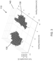
- Figure 2 depicts a first diagram showing the vehicle position in relation to a loading or unloading area.
- the diagram can be displayed to the operator on the interface 70 when the operator steers the vehicle 100 to a loading work site.
- the diagram shows a load placement area 130 depending on the actual log piles around a possible vehicle position.
- the position of the log piles or an unloading position can be entered manually into the operator interface 70 or can be directly imported from a map system used for the forestry production.
- the different cubes in Fig 2 represent the determined loading or unloading locations and can be of different color or in different shadings and be displayed a heat map with different color indicators or different graphical representations, depending on the assumed fuel consumption of the vehicle 100 regarding the load distance and a resulting crane reach for loading or unloading the logs.
- the locations of the log can also be integrated via an interface using a camera for identification of logs in the view field of the camera, being mounted on the vehicle 100.
- the center position of the vehicle 100 is the estimated optimal position of the vehicle 100 and is used to guide the operator towards that position.
- Figure 2 represents the state when the vehicle 100 is stopped at the calculated optimal position.
- the operation system 10 can display a map or an approach route to the calculated position so that the operator is guided through the correct approach and is relieved of any stress or workload to plan the approach.
- the approach can also estimate the best route, having access to the vehicles map data and thus to the terrain conditions, slopes, obstacles or soft ground conditions.
- the weight can be an estimation based on the production data, having a length and amount of logs of a specific tree type.
- the weight can also be transferred from a harvester vehicle which records the total amount and weight of the harvested trees.
- the weight estimation can then be used to calculate the hydraulic power necessary to lift the load based on the position of the vehicle 100 and the resulting crane reach.
- the operation system 10 can further optimize regarding the estimated loading time.
- the loading matrix is not calculated regarding fuel consumption but crane reach and estimated crane movement time.
- the time optimized mode may be contrary to the optimized fuel matrix 110, as the crane reach may be higher, or the hydraulic pump power consumption may be higher.
- the operation system 10 calculates a stopping position for an optimized loading time and directs the operator towards that position and advises the correct stopping moment.
Landscapes
- Engineering & Computer Science (AREA)
- Mechanical Engineering (AREA)
- Automation & Control Theory (AREA)
- Jib Cranes (AREA)
- Combined Controls Of Internal Combustion Engines (AREA)
Priority Applications (3)
| Application Number | Priority Date | Filing Date | Title |
|---|---|---|---|
| EP23202053.7A EP4534470A1 (fr) | 2023-10-06 | 2023-10-06 | Système d'exploitation |
| AU2024219375A AU2024219375A1 (en) | 2023-10-06 | 2024-09-04 | Operation system |
| CA3255556A CA3255556A1 (en) | 2023-10-06 | 2024-09-04 | Operation system |
Applications Claiming Priority (1)
| Application Number | Priority Date | Filing Date | Title |
|---|---|---|---|
| EP23202053.7A EP4534470A1 (fr) | 2023-10-06 | 2023-10-06 | Système d'exploitation |
Publications (1)
| Publication Number | Publication Date |
|---|---|
| EP4534470A1 true EP4534470A1 (fr) | 2025-04-09 |
Family
ID=88295758
Family Applications (1)
| Application Number | Title | Priority Date | Filing Date |
|---|---|---|---|
| EP23202053.7A Pending EP4534470A1 (fr) | 2023-10-06 | 2023-10-06 | Système d'exploitation |
Country Status (3)
| Country | Link |
|---|---|
| EP (1) | EP4534470A1 (fr) |
| AU (1) | AU2024219375A1 (fr) |
| CA (1) | CA3255556A1 (fr) |
Citations (3)
| Publication number | Priority date | Publication date | Assignee | Title |
|---|---|---|---|---|
| EP3568001A1 (fr) * | 2017-01-10 | 2019-11-20 | Ponsse Oyj | Procédé et agencement pour commander le fonctionnement d'un dispositif de manipulation de bois dans un engin de chantier, et engin forestier |
| EP3832584A1 (fr) * | 2018-08-02 | 2021-06-09 | Tadano Ltd. | Module d'aide au fonctionnement, application de génération d'image et machine de travail |
| EP3925921A1 (fr) * | 2019-02-14 | 2021-12-22 | Tadano Ltd. | Grue et système de génération de trajet pour grue |
-
2023
- 2023-10-06 EP EP23202053.7A patent/EP4534470A1/fr active Pending
-
2024
- 2024-09-04 AU AU2024219375A patent/AU2024219375A1/en active Pending
- 2024-09-04 CA CA3255556A patent/CA3255556A1/en active Pending
Patent Citations (3)
| Publication number | Priority date | Publication date | Assignee | Title |
|---|---|---|---|---|
| EP3568001A1 (fr) * | 2017-01-10 | 2019-11-20 | Ponsse Oyj | Procédé et agencement pour commander le fonctionnement d'un dispositif de manipulation de bois dans un engin de chantier, et engin forestier |
| EP3832584A1 (fr) * | 2018-08-02 | 2021-06-09 | Tadano Ltd. | Module d'aide au fonctionnement, application de génération d'image et machine de travail |
| EP3925921A1 (fr) * | 2019-02-14 | 2021-12-22 | Tadano Ltd. | Grue et système de génération de trajet pour grue |
Also Published As
| Publication number | Publication date |
|---|---|
| CA3255556A1 (en) | 2025-05-23 |
| AU2024219375A1 (en) | 2025-04-24 |
Similar Documents
| Publication | Publication Date | Title |
|---|---|---|
| USRE50412E1 (en) | System and method for coupling an implement to a work vehicle | |
| US12523017B2 (en) | Excavation plan creation device, working machine, and excavation plan creation method | |
| US10731318B2 (en) | System and method for coupling an implement to a work vehicle | |
| US7865285B2 (en) | Machine control system and method | |
| US11937554B2 (en) | Method and arrangement to control the operation of a wood-handling device in a work machine, and a forest machine | |
| US20230279634A1 (en) | Work machine and control device for work machine | |
| KR20210020896A (ko) | 자율 작동 작업 기계의 작동 방법 및 장치 | |
| US11462030B2 (en) | Method and system for detecting a pile | |
| US20170268198A1 (en) | Control system for work vehicle, control method, and work vehicle | |
| US11634891B2 (en) | System and method for navigating an operator to couple a self-propelled vehicle with an attachment implement therefor | |
| US20170096797A1 (en) | Operator assist features for excavating machines based on perception system feedback | |
| EP4545712A1 (fr) | Système comprenant un engin de chantier, dispositif de commande d'engin de chantier et procédé de commande d'engin de chantier | |
| EP4534470A1 (fr) | Système d'exploitation | |
| EP4013216B1 (fr) | Procédé et système dans une machine forestière | |
| CN114506277B (zh) | 用于作业车辆和作业机具的引导显示系统 | |
| US12559916B2 (en) | Work machine control system for indicating implement position | |
| BR102024018348A2 (pt) | Sistema de operação | |
| US11021853B1 (en) | Connection system for coupling an implement to a work vehicle with alignment indicator system | |
| US12467229B2 (en) | Work machine stabilization | |
| EP4545713A1 (fr) | Système comprenant un engin de chantier et procédé de commande d'un engin de chantier | |
| KR102893305B1 (ko) | 트랙터의 견인력 제어 기반 고효율 농작업 관리 방법 및 장치 | |
| EP4632156A1 (fr) | Système d'assistance de préhension automatique pour engin de chantier et procédé de commande d'assistance de préhension automatique pour engin de chantier | |
| EP4599662A1 (fr) | Procédé de fonctionnement d'un outil agricole | |
| CN119160668A (zh) | 一种装车系统和方法 |
Legal Events
| Date | Code | Title | Description |
|---|---|---|---|
| PUAI | Public reference made under article 153(3) epc to a published international application that has entered the european phase |
Free format text: ORIGINAL CODE: 0009012 |
|
| STAA | Information on the status of an ep patent application or granted ep patent |
Free format text: STATUS: THE APPLICATION HAS BEEN PUBLISHED |
|
| AK | Designated contracting states |
Kind code of ref document: A1 Designated state(s): AL AT BE BG CH CY CZ DE DK EE ES FI FR GB GR HR HU IE IS IT LI LT LU LV MC ME MK MT NL NO PL PT RO RS SE SI SK SM TR |
|
| STAA | Information on the status of an ep patent application or granted ep patent |
Free format text: STATUS: REQUEST FOR EXAMINATION WAS MADE |
|
| 17P | Request for examination filed |
Effective date: 20251009 |