EP4534727A1 - Appareil de serrage, électrolyseur, procédé de fermeture/ouverture de cellules d'électrolyse adjacentes, procédé d'application rétroactive d'appareil de serrage - Google Patents
Appareil de serrage, électrolyseur, procédé de fermeture/ouverture de cellules d'électrolyse adjacentes, procédé d'application rétroactive d'appareil de serrage Download PDFInfo
- Publication number
- EP4534727A1 EP4534727A1 EP23201744.2A EP23201744A EP4534727A1 EP 4534727 A1 EP4534727 A1 EP 4534727A1 EP 23201744 A EP23201744 A EP 23201744A EP 4534727 A1 EP4534727 A1 EP 4534727A1
- Authority
- EP
- European Patent Office
- Prior art keywords
- pressure plate
- movable member
- tightening apparatus
- actuator
- electrolyser
- Prior art date
- Legal status (The legal status is an assumption and is not a legal conclusion. Google has not performed a legal analysis and makes no representation as to the accuracy of the status listed.)
- Withdrawn
Links
Images







Classifications
-
- C—CHEMISTRY; METALLURGY
- C25—ELECTROLYTIC OR ELECTROPHORETIC PROCESSES; APPARATUS THEREFOR
- C25B—ELECTROLYTIC OR ELECTROPHORETIC PROCESSES FOR THE PRODUCTION OF COMPOUNDS OR NON-METALS; APPARATUS THEREFOR
- C25B9/00—Cells or assemblies of cells; Constructional parts of cells; Assemblies of constructional parts, e.g. electrode-diaphragm assemblies; Process-related cell features
- C25B9/05—Pressure cells
-
- C—CHEMISTRY; METALLURGY
- C25—ELECTROLYTIC OR ELECTROPHORETIC PROCESSES; APPARATUS THEREFOR
- C25B—ELECTROLYTIC OR ELECTROPHORETIC PROCESSES FOR THE PRODUCTION OF COMPOUNDS OR NON-METALS; APPARATUS THEREFOR
- C25B15/00—Operating or servicing cells
-
- C—CHEMISTRY; METALLURGY
- C25—ELECTROLYTIC OR ELECTROPHORETIC PROCESSES; APPARATUS THEREFOR
- C25B—ELECTROLYTIC OR ELECTROPHORETIC PROCESSES FOR THE PRODUCTION OF COMPOUNDS OR NON-METALS; APPARATUS THEREFOR
- C25B9/00—Cells or assemblies of cells; Constructional parts of cells; Assemblies of constructional parts, e.g. electrode-diaphragm assemblies; Process-related cell features
- C25B9/60—Constructional parts of cells
-
- C—CHEMISTRY; METALLURGY
- C25—ELECTROLYTIC OR ELECTROPHORETIC PROCESSES; APPARATUS THEREFOR
- C25B—ELECTROLYTIC OR ELECTROPHORETIC PROCESSES FOR THE PRODUCTION OF COMPOUNDS OR NON-METALS; APPARATUS THEREFOR
- C25B9/00—Cells or assemblies of cells; Constructional parts of cells; Assemblies of constructional parts, e.g. electrode-diaphragm assemblies; Process-related cell features
- C25B9/70—Assemblies comprising two or more cells
- C25B9/73—Assemblies comprising two or more cells of the filter-press type
- C25B9/75—Assemblies comprising two or more cells of the filter-press type having bipolar electrodes
-
- C—CHEMISTRY; METALLURGY
- C25—ELECTROLYTIC OR ELECTROPHORETIC PROCESSES; APPARATUS THEREFOR
- C25B—ELECTROLYTIC OR ELECTROPHORETIC PROCESSES FOR THE PRODUCTION OF COMPOUNDS OR NON-METALS; APPARATUS THEREFOR
- C25B9/00—Cells or assemblies of cells; Constructional parts of cells; Assemblies of constructional parts, e.g. electrode-diaphragm assemblies; Process-related cell features
- C25B9/70—Assemblies comprising two or more cells
- C25B9/73—Assemblies comprising two or more cells of the filter-press type
- C25B9/77—Assemblies comprising two or more cells of the filter-press type having diaphragms
-
- C—CHEMISTRY; METALLURGY
- C25—ELECTROLYTIC OR ELECTROPHORETIC PROCESSES; APPARATUS THEREFOR
- C25B—ELECTROLYTIC OR ELECTROPHORETIC PROCESSES FOR THE PRODUCTION OF COMPOUNDS OR NON-METALS; APPARATUS THEREFOR
- C25B1/00—Electrolytic production of inorganic compounds or non-metals
- C25B1/01—Products
- C25B1/02—Hydrogen or oxygen
- C25B1/04—Hydrogen or oxygen by electrolysis of water
Definitions
- Electrolysers for such a process comprising a plurality of electrolysis unit cells (referred to simply as “cells” or “elements”) arranged in series. Each cell defines an anode chamber and a cathode chamber, which are physically divided by a partition wall within the cell. Separators, such as ion exchange membranes or diaphragms, are arranged between the respective adjacent cells to electrochemically separate the anode chamber and the cathode chamber from each other. In order to establish a seal between the adjacent cells, gaskets or the like are arranged on the opposite sides of each cell, and the cells are tightened against each other in the cell stacking direction with aid of a tightening apparatus according to a filter press technology.
- EP4137610 A1 discloses an oil pressure tightening device comprising an oil pressure cylinder, a shut-off valve, a relief valve, an oil tank and a pump.
- JP 2021195596 A teaches that stack pressure for bipolar electrolysis elements is controlled by a hydraulic control mechanism.
- a tightening apparatus for selectively opening and closing respective adjacent electrolysis cells arranged in series in an electrolyser.
- the tightening apparatus comprises: a movable member moveable in a first direction and a second direction, the first direction being a direction in which the cells are to be closed each other and the second direction being an opposite direction to the first direction; at least one actuator configured to move the movable member selectively in the first and second directions; a pressure plate arranged on the first direction side with respect to the movable member; and a spacer arranged between the pressure plate and the movable member.
- the tightening apparatus may comprise two or more spacers arranged in tandem with each other in the first direction so as to provide three (or more)-step movements of the pressure plate. Additionally or alternatively, the moving distance of the pressure plate in the first direction may vary by adjusting the length of the spacer.
- the invented tightening apparatus significantly reduces the labour load compared to the conventional tie-rod tightening system.
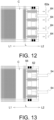
- the method comprises: moving the pressure plate and the movable member in the first direction with an aid of the at least one actuator; moving the movable member in the second direction using the at least one actuator so that a space is created between the pressure plate and the movable member; interconnecting the pressure plate and the movable member with the spacer to hold the created space; and tightening the respective adjacent electrolysis cells by moving the pressure plate in the first direction along with the movable plate via the spacer therebetween with an aid of the at least one actuator.
- the present invention provides a method of opening adjacent electrolysis cells in an electrolyser, using the invented tightening apparatus.
- the method comprises: interconnecting the pressure plate and at least one electrolysis cell with each other; moving the movable member in the second direction along with the pressure plate and the least one electrolysis cell connected thereto using the at least one actuator; releasing or deactivating the spacer between the pressure plate and the movable member; moving the movable member in the first direction into contact with the pressure plate; interconnecting the pressure plate and the movable member; and moving the pressure plate along with the movable member in the second direction using the at least one actuator.
- One exemplary electrolyser to which the invented tightening apparatus may be applied is a bipolar electrolyser, such as ion-exchange membrane process electrolyser, in which a plurality of bipolar electrolysis cells are arranged in series, with an ion exchange membrane or diaphragm as a gas separator being interposed between the respective adjacent cells ( FIG. 1 ).
- the filter press technology is utilized to join the adjacent cells so that there is substantially no gap between electrode elements on both sides of the separator.
- the electrolyser may be a monopolar electrolyser in which each cell has either a cathode or anode electrode element on the side (not shown).
- the electrolyser in which the invented tightening apparatus is applied may be used for Chlor-Alkali electrolysis.
- the electrolyser may be used for alkaline water electrolysis (AWE).
- AWE alkaline water electrolysis
- the electrolyser may be applicable to any electrolysis process using a plurality of unit cells arranged in series, with an electrochemical separator being interposed between the respective adjacent unit cells.
- Each cell 10 may comprise a first electrode element 12A (e.g., cathode), a second electrode element 12B (e.g., anode).
- Gas separators 14 are interposed between the respective adjacent cells 10.
- the electrolysis cell 10 may further comprise a first compartment 16A, a second compartment 16B and current collectors 18A, 18B.
- the current collectors 18A, 18B may also be referred as part of electrode structures.
- the first and second compartments 16A, 16B are physically divided from each other by a rear wall or partition wall 20.
- the partition wall 20 faces the separators 14 over the first and second compartments 16A, 16B, and define these compartments together with the separators 14.
- Each separator 14 has a first surface side and a second surface side, wherein the first surface side contacts the first compartment 16A and the second surface side contacts the second compartment 16B for electrochemically interconnecting the first compartment 16A and the second compartment 16B of the adjacent cells 10.
- the separator 14 may be ion-exchange membrane.
- the separator 14 may be porous diaphragm, particularly an ion-permeable diaphragm. Ion-permeable diaphragms do not allow gases generated by the electrochemical reaction to permeate, but have ion-exchange function.
- the separator 14 may be a polymeric porous membrane, inorganic porous membrane, woven or nonwoven fabrics, or the like. It should be noted that the electrolyser described above is merely an example, and the tightening apparatus of the present invention is applicable to any electrolysers using filter press technology.
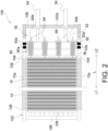
- an electrolyser 100 having an exemplary tightening apparatus 50 according to the present invention can be seen in planer view.
- a plurality of electrolysis cells 10 such as illustrated in FIG. 1 can been seen. These cells 10 are stacked in series, e.g., in the longitudinal direction L of the electrolyser 100.
- the electrolyser 100 comprises a frame 102 for supporting the electrolysis cells 10.
- the frame 102 may include a pair of guide rails 104 extending in the stacking direction L of the cells 10 to support the respective cells 10.
- the cells 10 are suspended between the pair of guide rails 104. Additional guide means may also be provided.
- the frame 102 includes four pillars (not shown).
- Each guide rail 104 spans between the front pillar and the rear pillar in the stacking direction L.
- each cell 10 includes a pair of rolling elements 10a on its sides so that the cell 10 can move or slide on the guide rails 104 with low friction.
- the guide rails 104 may also support some components of the tightening apparatus 50 as discussed later.
- the frame 102 may further include two or more beams or lateral bars 106.
- the lateral bar 106 on the front side may span between the front pillars.
- the lateral bar 106 on the rear side may span between the rear pillars.
- a support plate 108 is provided to receive pressure from the terminal cell 10E at the distal end of the electrolyser 100.
- the support plate 108 is attached to the frame, e.g., the rear bar 106.
- the movable member 52 is arranged between the pressure plate 56 and the at least one actuator 54.
- the movable member 52 is configured to move in the first and second directions L1, L2 with an aid of the at least one actuator 54.
- the movable member 52 may move or slide on the guide rails 104.
- the movable member 52 may include rolling elements 52a on its sides that roll on the guide rails 104.
- the movable member 52 may have a plurality of openings 52b through which the spacers (the compressible means 60) extend.
- the actuator 54 is configured to move the movable member 52 selectively in the first and second directions L1, L2.
- Various actuators such as hydraulic cylinders, electro-mechanical actuators, pneumatic actuators, are applicable.
- a hydraulic cylinder is used as the actuator 54.
- the tightening apparatus 50 comprises all necessary equipment for the actuator(s) 54 to work properly.
- the hydraulic cylinders require a hydraulic circuit that comprises a reservoir, pump, relief valve, 3-way or 4-way directional control valve, connectors, hydraulic lines, controller and the like.
- the electro-mechanical actuators require electric motors, power supply, transmissions, controller and the like.
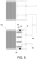
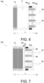
- the one or more spacers are arranged between the pressure plate 56 and the movable member 52.
- the function of each spacer may selectively activated and deactivated.
- the spacers may be arranged to be in line with the respective openings 52b of the movable member 52 in the direction L.
- the proximal end (the end on the second direction L2 side) of each spacer freely passes through the opening 52b of the movable member 52.
- the proximal end of each spacer is engaged with, or connected to, the movable member 52.
- the spacer(s) may have a rigid body that does not substantially deform due to external pressure from actuator 54.
- each spacer comprises the compressible means 60.
- the compressible means 60 are arranged between the pressure plate 56 and the movable member 52.
- Each compressible means 60 is compressible by the movable member 52 with an aid of the at least one actuator 54 so as to accumulate pressure and apply in turn said pressure to the pressure plate 56.
- the compressible means 60 may comprise a spring, preferably a belleville spring 60a.
- Each belleville spring 60a is guided by a centre rod 60b.
- the centre rod 60b extends from the pressure plate 56 in the second direction L2.
- the centre rods 60b align with the openings 52b of the movable plate 52 viewed in the direction L.
- the compressible means 60 may be placed at the same location where the existing tie rods were located.
- the plurality of compressible means 60 may be distributed substantially evenly around the perimeter of the pressure plate 56. More preferably, one or more compressible means 60 are positioned on the outside near the seals (e.g., gaskets) between the cells 10, viewed in the stacking direction L of the cells 10.
- locking means e.g., nuts
- the locking means 64 are attached before compressing the compressible means 60, because if the locking means 64 are attached after compressing the compressible means 60, compressible means 60 may expand due to the decrease in thickness of the gasket used in the cell unit over time.
- the main function of locking means 64 are to retain the compressible means 60, especially in the opening procedure.
Landscapes
- Chemical & Material Sciences (AREA)
- Engineering & Computer Science (AREA)
- Chemical Kinetics & Catalysis (AREA)
- Electrochemistry (AREA)
- Materials Engineering (AREA)
- Metallurgy (AREA)
- Organic Chemistry (AREA)
- Electrolytic Production Of Non-Metals, Compounds, Apparatuses Therefor (AREA)
Priority Applications (3)
| Application Number | Priority Date | Filing Date | Title |
|---|---|---|---|
| EP23201744.2A EP4534727A1 (fr) | 2023-10-05 | 2023-10-05 | Appareil de serrage, électrolyseur, procédé de fermeture/ouverture de cellules d'électrolyse adjacentes, procédé d'application rétroactive d'appareil de serrage |
| PCT/EP2024/077573 WO2025073679A1 (fr) | 2023-10-05 | 2024-10-01 | Appareil de serrage, électrolyseur, procédé de fermeture/ouverture de cellules d'électrolyse adjacentes, procédé d'application rétroactive d'appareil de serrage |
| CN202480063553.3A CN122029308A (zh) | 2023-10-05 | 2024-10-01 | 收紧装置、电解装置、关闭/打开相邻电解池的方法、追溯地应用收紧装置的方法 |
Applications Claiming Priority (1)
| Application Number | Priority Date | Filing Date | Title |
|---|---|---|---|
| EP23201744.2A EP4534727A1 (fr) | 2023-10-05 | 2023-10-05 | Appareil de serrage, électrolyseur, procédé de fermeture/ouverture de cellules d'électrolyse adjacentes, procédé d'application rétroactive d'appareil de serrage |
Publications (1)
| Publication Number | Publication Date |
|---|---|
| EP4534727A1 true EP4534727A1 (fr) | 2025-04-09 |
Family
ID=88290874
Family Applications (1)
| Application Number | Title | Priority Date | Filing Date |
|---|---|---|---|
| EP23201744.2A Withdrawn EP4534727A1 (fr) | 2023-10-05 | 2023-10-05 | Appareil de serrage, électrolyseur, procédé de fermeture/ouverture de cellules d'électrolyse adjacentes, procédé d'application rétroactive d'appareil de serrage |
Country Status (3)
| Country | Link |
|---|---|
| EP (1) | EP4534727A1 (fr) |
| CN (1) | CN122029308A (fr) |
| WO (1) | WO2025073679A1 (fr) |
Citations (7)
| Publication number | Priority date | Publication date | Assignee | Title |
|---|---|---|---|---|
| US4846952A (en) * | 1988-07-15 | 1989-07-11 | The Dow Chemical Company | Flat plate electrolysis cell frame separator and method |
| EP0410478A2 (fr) * | 1989-07-27 | 1991-01-30 | De Nora Permelec S.P.A. | Presse à stratifier |
| EP0505899A1 (fr) | 1991-03-18 | 1992-09-30 | Asahi Kasei Kogyo Kabushiki Kaisha | Cellule d'électrolyse du type filtre-presse bipolaire |
| JP2021195596A (ja) | 2020-06-15 | 2021-12-27 | 旭化成株式会社 | アルカリ水電解槽 |
| EP4112782A1 (fr) * | 2021-06-30 | 2023-01-04 | Siemens Energy Global GmbH & Co. KG | Dispositif de montage, ainsi qu'utilisation du dispositif de montage pour le montage des cellules d'électrolyse d'un électrolyseur |
| EP4137610A1 (fr) | 2020-04-16 | 2023-02-22 | Asahi Kasei Kabushiki Kaisha | Système d'électrolyse et son procédé d'utilisation |
| KR102525589B1 (ko) * | 2022-05-13 | 2023-04-25 | 고등기술연구원연구조합 | 수전해 스택 모듈 적층 장치 |
-
2023
- 2023-10-05 EP EP23201744.2A patent/EP4534727A1/fr not_active Withdrawn
-
2024
- 2024-10-01 WO PCT/EP2024/077573 patent/WO2025073679A1/fr active Pending
- 2024-10-01 CN CN202480063553.3A patent/CN122029308A/zh active Pending
Patent Citations (7)
| Publication number | Priority date | Publication date | Assignee | Title |
|---|---|---|---|---|
| US4846952A (en) * | 1988-07-15 | 1989-07-11 | The Dow Chemical Company | Flat plate electrolysis cell frame separator and method |
| EP0410478A2 (fr) * | 1989-07-27 | 1991-01-30 | De Nora Permelec S.P.A. | Presse à stratifier |
| EP0505899A1 (fr) | 1991-03-18 | 1992-09-30 | Asahi Kasei Kogyo Kabushiki Kaisha | Cellule d'électrolyse du type filtre-presse bipolaire |
| EP4137610A1 (fr) | 2020-04-16 | 2023-02-22 | Asahi Kasei Kabushiki Kaisha | Système d'électrolyse et son procédé d'utilisation |
| JP2021195596A (ja) | 2020-06-15 | 2021-12-27 | 旭化成株式会社 | アルカリ水電解槽 |
| EP4112782A1 (fr) * | 2021-06-30 | 2023-01-04 | Siemens Energy Global GmbH & Co. KG | Dispositif de montage, ainsi qu'utilisation du dispositif de montage pour le montage des cellules d'électrolyse d'un électrolyseur |
| KR102525589B1 (ko) * | 2022-05-13 | 2023-04-25 | 고등기술연구원연구조합 | 수전해 스택 모듈 적층 장치 |
Also Published As
| Publication number | Publication date |
|---|---|
| WO2025073679A1 (fr) | 2025-04-10 |
| CN122029308A (zh) | 2026-05-12 |
Similar Documents
| Publication | Publication Date | Title |
|---|---|---|
| KR20110095348A (ko) | 전기 분해 공정을 위한 원소 셀 및 관련 모듈형 전기 분해 장치 | |
| EP3277862B1 (fr) | Ensemble électrode-membrane pour une utilisation dans des électrolyseurs de solution aqueuse alcaline | |
| GB1561957A (en) | Electrolysis apparatus | |
| DE2835800A1 (de) | Separator-elektroden-einheit fuer elektrolytische zellen, zur einheit gehoeriger separator, verfahren zum zusammenbau der einheit und mit ihr versehene zelle | |
| WO2014040746A1 (fr) | Procédé et système de conduite d'un électrolyseur | |
| KR102525589B1 (ko) | 수전해 스택 모듈 적층 장치 | |
| EP4534726A1 (fr) | Appareil de serrage, électrolyseur, procédé de fermeture/de mise à jour de cellules d'électrolyse adjacentes, procédé d'application rétroactive d'appareil de serrage | |
| EP0055930B1 (fr) | Régulateur de la distance entre les électrodes pour une cellule électrolytique | |
| WO2025073679A1 (fr) | Appareil de serrage, électrolyseur, procédé de fermeture/ouverture de cellules d'électrolyse adjacentes, procédé d'application rétroactive d'appareil de serrage | |
| US4541911A (en) | Method of assembling a filter press type electrolytic cell | |
| EP2559093B1 (fr) | Bloc de piles électrochimiques | |
| DE4211555C1 (de) | Bipolare Filterpressenzelle zur Herstellung von Peroxodisulfaten | |
| US10041178B2 (en) | End pressure plate for electrolysers | |
| DE60204908T2 (de) | Verfahren zur wiederverwendung von stromsammel-/verteilerplatten von polymermembran-brennstoffzellenstapeln | |
| AT527258B1 (de) | Elektrolysezelle und Elektrolysevorrichtung mit einer Elektrolysezelle | |
| CN117286542B (zh) | 气液分离盒、双极板、电解槽及制氢系统 | |
| EP4193409A1 (fr) | Empilement de cellules élémentaires comprenant au moins deux rangées de cellules, dispositif de pile à combustible et véhicule à moteur | |
| CN114597447B (zh) | 电化学升压装置 | |
| AT528217B1 (de) | Elektrolysemodul und Elektrolyseur | |
| WO2025180771A1 (fr) | Concept cellulaire avec une nouvelle structure de cathode et un cadre cellulaire correspondant pour l'électrolyse d'eau alcaline | |
| US20250129492A1 (en) | Electrolyzer stacks, electrolysis systems, and methods for operating electrolysis systems | |
| CA3219610C (fr) | Electrolyseur ayant des elements a cellules multiples | |
| DE202024103952U1 (de) | Elektrolyseur mit PEM-Zellstapel und einer Zellstapel-Spannvorrichtung | |
| KR20240023183A (ko) | 멀티-셀 요소들을 갖는 전해조 | |
| EP4713504A1 (fr) | Cellule électrolytique, bloc électrolytique comprenant plusieurs cellules électrolytiques correspondantes et dispositif électrolytique doté de plusieurs cellules électrolytiques correspondantes |
Legal Events
| Date | Code | Title | Description |
|---|---|---|---|
| PUAI | Public reference made under article 153(3) epc to a published international application that has entered the european phase |
Free format text: ORIGINAL CODE: 0009012 |
|
| STAA | Information on the status of an ep patent application or granted ep patent |
Free format text: STATUS: THE APPLICATION HAS BEEN PUBLISHED |
|
| AK | Designated contracting states |
Kind code of ref document: A1 Designated state(s): AL AT BE BG CH CY CZ DE DK EE ES FI FR GB GR HR HU IE IS IT LI LT LU LV MC ME MK MT NL NO PL PT RO RS SE SI SK SM TR |
|
| STAA | Information on the status of an ep patent application or granted ep patent |
Free format text: STATUS: THE APPLICATION IS DEEMED TO BE WITHDRAWN |
|
| 18D | Application deemed to be withdrawn |
Effective date: 20251010 |