EP4534729A2 - Electrode structure - Google Patents
Electrode structure Download PDFInfo
- Publication number
- EP4534729A2 EP4534729A2 EP24191367.2A EP24191367A EP4534729A2 EP 4534729 A2 EP4534729 A2 EP 4534729A2 EP 24191367 A EP24191367 A EP 24191367A EP 4534729 A2 EP4534729 A2 EP 4534729A2
- Authority
- EP
- European Patent Office
- Prior art keywords
- catalyst layer
- outer edge
- layer
- gas diffusion
- catalyst
- Prior art date
- Legal status (The legal status is an assumption and is not a legal conclusion. Google has not performed a legal analysis and makes no representation as to the accuracy of the status listed.)
- Pending
Links
Images

Classifications
-
- H—ELECTRICITY
- H01—ELECTRIC ELEMENTS
- H01M—PROCESSES OR MEANS, e.g. BATTERIES, FOR THE DIRECT CONVERSION OF CHEMICAL ENERGY INTO ELECTRICAL ENERGY
- H01M8/00—Fuel cells; Manufacture thereof
- H01M8/10—Fuel cells with solid electrolytes
- H01M8/1004—Fuel cells with solid electrolytes characterised by membrane-electrode assemblies [MEA]
-
- C—CHEMISTRY; METALLURGY
- C25—ELECTROLYTIC OR ELECTROPHORETIC PROCESSES; APPARATUS THEREFOR
- C25B—ELECTROLYTIC OR ELECTROPHORETIC PROCESSES FOR THE PRODUCTION OF COMPOUNDS OR NON-METALS; APPARATUS THEREFOR
- C25B1/00—Electrolytic production of inorganic compounds or non-metals
- C25B1/01—Products
- C25B1/02—Hydrogen or oxygen
- C25B1/04—Hydrogen or oxygen by electrolysis of water
-
- C—CHEMISTRY; METALLURGY
- C25—ELECTROLYTIC OR ELECTROPHORETIC PROCESSES; APPARATUS THEREFOR
- C25B—ELECTROLYTIC OR ELECTROPHORETIC PROCESSES FOR THE PRODUCTION OF COMPOUNDS OR NON-METALS; APPARATUS THEREFOR
- C25B9/00—Cells or assemblies of cells; Constructional parts of cells; Assemblies of constructional parts, e.g. electrode-diaphragm assemblies; Process-related cell features
- C25B9/17—Cells comprising dimensionally-stable non-movable electrodes; Assemblies of constructional parts thereof
- C25B9/19—Cells comprising dimensionally-stable non-movable electrodes; Assemblies of constructional parts thereof with diaphragms
- C25B9/23—Cells comprising dimensionally-stable non-movable electrodes; Assemblies of constructional parts thereof with diaphragms comprising ion-exchange membranes in or on which electrode material is embedded
-
- C—CHEMISTRY; METALLURGY
- C25—ELECTROLYTIC OR ELECTROPHORETIC PROCESSES; APPARATUS THEREFOR
- C25B—ELECTROLYTIC OR ELECTROPHORETIC PROCESSES FOR THE PRODUCTION OF COMPOUNDS OR NON-METALS; APPARATUS THEREFOR
- C25B9/00—Cells or assemblies of cells; Constructional parts of cells; Assemblies of constructional parts, e.g. electrode-diaphragm assemblies; Process-related cell features
- C25B9/70—Assemblies comprising two or more cells
- C25B9/73—Assemblies comprising two or more cells of the filter-press type
- C25B9/75—Assemblies comprising two or more cells of the filter-press type having bipolar electrodes
-
- C—CHEMISTRY; METALLURGY
- C25—ELECTROLYTIC OR ELECTROPHORETIC PROCESSES; APPARATUS THEREFOR
- C25B—ELECTROLYTIC OR ELECTROPHORETIC PROCESSES FOR THE PRODUCTION OF COMPOUNDS OR NON-METALS; APPARATUS THEREFOR
- C25B9/00—Cells or assemblies of cells; Constructional parts of cells; Assemblies of constructional parts, e.g. electrode-diaphragm assemblies; Process-related cell features
- C25B9/70—Assemblies comprising two or more cells
- C25B9/73—Assemblies comprising two or more cells of the filter-press type
- C25B9/77—Assemblies comprising two or more cells of the filter-press type having diaphragms
-
- H—ELECTRICITY
- H01—ELECTRIC ELEMENTS
- H01M—PROCESSES OR MEANS, e.g. BATTERIES, FOR THE DIRECT CONVERSION OF CHEMICAL ENERGY INTO ELECTRICAL ENERGY
- H01M4/00—Electrodes
- H01M4/86—Inert electrodes with catalytic activity, e.g. for fuel cells
- H01M4/8605—Porous electrodes
-
- H—ELECTRICITY
- H01—ELECTRIC ELEMENTS
- H01M—PROCESSES OR MEANS, e.g. BATTERIES, FOR THE DIRECT CONVERSION OF CHEMICAL ENERGY INTO ELECTRICAL ENERGY
- H01M4/00—Electrodes
- H01M4/86—Inert electrodes with catalytic activity, e.g. for fuel cells
- H01M4/8636—Inert electrodes with catalytic activity, e.g. for fuel cells with a gradient in another property than porosity
- H01M4/8642—Gradient in composition
-
- H—ELECTRICITY
- H01—ELECTRIC ELEMENTS
- H01M—PROCESSES OR MEANS, e.g. BATTERIES, FOR THE DIRECT CONVERSION OF CHEMICAL ENERGY INTO ELECTRICAL ENERGY
- H01M4/00—Electrodes
- H01M4/86—Inert electrodes with catalytic activity, e.g. for fuel cells
- H01M4/88—Processes of manufacture
- H01M4/8803—Supports for the deposition of the catalytic active composition
- H01M4/881—Electrolytic membranes
-
- H—ELECTRICITY
- H01—ELECTRIC ELEMENTS
- H01M—PROCESSES OR MEANS, e.g. BATTERIES, FOR THE DIRECT CONVERSION OF CHEMICAL ENERGY INTO ELECTRICAL ENERGY
- H01M8/00—Fuel cells; Manufacture thereof
- H01M8/02—Details
- H01M8/0202—Collectors; Separators, e.g. bipolar separators; Interconnectors
- H01M8/023—Porous and characterised by the material
- H01M8/0241—Composites
- H01M8/0245—Composites in the form of layered or coated products
-
- C—CHEMISTRY; METALLURGY
- C25—ELECTROLYTIC OR ELECTROPHORETIC PROCESSES; APPARATUS THEREFOR
- C25B—ELECTROLYTIC OR ELECTROPHORETIC PROCESSES FOR THE PRODUCTION OF COMPOUNDS OR NON-METALS; APPARATUS THEREFOR
- C25B11/00—Electrodes; Manufacture thereof not otherwise provided for
- C25B11/02—Electrodes; Manufacture thereof not otherwise provided for characterised by shape or form
- C25B11/03—Electrodes; Manufacture thereof not otherwise provided for characterised by shape or form perforated or foraminous
- C25B11/031—Porous electrodes
- C25B11/032—Gas diffusion electrodes
-
- H—ELECTRICITY
- H01—ELECTRIC ELEMENTS
- H01M—PROCESSES OR MEANS, e.g. BATTERIES, FOR THE DIRECT CONVERSION OF CHEMICAL ENERGY INTO ELECTRICAL ENERGY
- H01M8/00—Fuel cells; Manufacture thereof
- H01M8/10—Fuel cells with solid electrolytes
- H01M2008/1095—Fuel cells with polymeric electrolytes
-
- Y—GENERAL TAGGING OF NEW TECHNOLOGICAL DEVELOPMENTS; GENERAL TAGGING OF CROSS-SECTIONAL TECHNOLOGIES SPANNING OVER SEVERAL SECTIONS OF THE IPC; TECHNICAL SUBJECTS COVERED BY FORMER USPC CROSS-REFERENCE ART COLLECTIONS [XRACs] AND DIGESTS
- Y02—TECHNOLOGIES OR APPLICATIONS FOR MITIGATION OR ADAPTATION AGAINST CLIMATE CHANGE
- Y02E—REDUCTION OF GREENHOUSE GAS [GHG] EMISSIONS, RELATED TO ENERGY GENERATION, TRANSMISSION OR DISTRIBUTION
- Y02E60/00—Enabling technologies; Technologies with a potential or indirect contribution to GHG emissions mitigation
- Y02E60/30—Hydrogen technology
- Y02E60/50—Fuel cells
Definitions
- the present invention relates to an electrode structure.
- H 2 hydrogen
- H 2 O water
- the solid polymer water electrolyzer has a cell stack with cells and separators stacked alternately. Each of the cells includes an electrolyte membrane, and a catalyst layer formed on each of both sides of the electrolyte membrane.
- a voltage is applied between an anode-side catalyst layer and a cathode-side catalyst layer and water is supplied to the anode-side catalyst layer. This causes electrochemical reactions as follows in the anode-side catalyst layer and the cathode-side catalyst layer.
- hydrogen is output from the cathode-side catalyst layer.
- the conventional solid polymer water electrolyzer is described in Japanese Patent Application Laid-Open No. 2022-023996 , for example.
- the catalyst layer is entirely used as an electrode.
- a formation range of the catalyst layer relative to the electrolyte membrane is determined with low accuracy, using the catalyst layer entirely as an electrode causes fluctuation of an effective region to practically function as an electrode. The same problem might occur not only in the cell of the solid polymer water electrolyzer but also in a cell of a solid polymer fuel cell.
- the present invention is intended to provide a technique that achieves reduction in fluctuation of an effective region to function as an electrode even if a formation range of a catalyst layer is determined with low accuracy.
- a first aspect of the present invention is intended for an electrode structure comprising: an electrolyte membrane; a first catalyst layer formed on one of surfaces of the electrolyte membrane; a first gas diffusion layer stacked on a surface of the first catalyst layer; a second catalyst layer formed on the other surface of the electrolyte membrane; and a porous transport layer or a second gas diffusion layer stacked on a surface of the second catalyst layer.
- An outer edge of the first gas diffusion layer is arranged at a more inward position than an outer edge of the porous transport layer or the second gas diffusion layer, an outer edge of the first catalyst layer, and an outer edge of the second catalyst layer.
- an effective region of the first catalyst layer and the second catalyst layer is defined using the first gas diffusion layer.
- the first catalyst layer and the second catalyst layer may have an overlapping region where the first catalyst layer and the second catalyst layer overlap each other and the outer edge of the first catalyst layer and the outer edge of the second catalyst layer may be at positions differing from each other, and the outer edge of the first gas diffusion layer may be arranged at a more inward position than an outer edge of the overlapping region.
- the first gas diffusion layer may have a rectangular shape and all the four sides of the outer edge of the first gas diffusion layer may be arranged at more inward positions than the outer edge of the porous transport layer or the second gas diffusion layer, the outer edge of the first catalyst layer, and the outer edge of the second catalyst layer.
- a second aspect of the present invention is intended for an electrode structure comprising: an electrolyte membrane; a first catalyst layer formed on one of surfaces of the electrolyte membrane; a first gas diffusion layer stacked on a surface of the first catalyst layer; a second catalyst layer formed on the other surface of the electrolyte membrane; and a second gas diffusion layer stacked on a surface of the second catalyst layer.
- a outer edge of the second gas diffusion layer is arranged at a more inward position than an outer edge of the first gas diffusion layer, an outer edge of the first catalyst layer, and an outer edge of the second catalyst layer.
- an effective region of the first catalyst layer and the second catalyst layer is defined using the second gas diffusion layer.
- the first catalyst layer and the second catalyst layer may have an overlapping region where the first catalyst layer and the second catalyst layer overlap each other and the outer edge of the first catalyst layer and the outer edge of the second catalyst layer may be at positions differing from each other, and the outer edge of the second gas diffusion layer may be arranged at a more inward position than an outer edge of the overlapping region.
- the second gas diffusion layer may have a rectangular shape and all the four sides of the outer edge of the second gas diffusion layer may be arranged at more inward positions than the outer edge of the first gas diffusion layer, the outer edge of the first catalyst layer, and the outer edge of the second catalyst layer.
- the first catalyst layer and the second catalyst layer may be coating films.
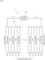
- Fig. 1 is a schematic view of a water electrolyzer 1.
- the water electrolyzer 1 is to produce hydrogen by solid polymer water electrolysis.
- the water electrolyzer 1 includes a cell stack 30 with a plurality of cells 10 and a plurality of separators 20, and a power supply 40.
- the cells 10 and the separators 20 are stacked alternately to form the cell stack 30.
- a direction in which the cells 10 and the separators 20 are stacked will be called a "stacking direction.”
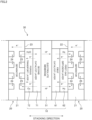
- Fig. 2 schematically shows only one cell 10 and separators 20 in a pair arranged on both sides of this cell 10 that form the cell stack 30 of the water electrolyzer 1.
- one cell 10 includes an electrolyte membrane 51, a first catalyst layer 61, a first gas diffusion layer 62, a second catalyst layer 71, and a porous transport layer 72.
- a stacked body composed of the electrolyte membrane 51, the first catalyst layer 61, the first gas diffusion layer 62, the second catalyst layer 71, and the porous transport layer 72 is called a membrane-electrode-assembly (EMA).
- EMA membrane-electrode-assembly
- a stacked body composed of the electrolyte membrane 51, the first catalyst layer 61, and the second catalyst layer 71 is called a catalyst-coated membrane (CCM).
- the electrolyte membrane 51 is a membrane having ion conductivity (ion-exchange membrane).
- the electrolyte membrane 51 of the present preferred embodiment is a proton-exchange membrane that conducts hydrogen ions (H + ).
- a fluorine-based or hydrocarbon-based polymer electrolyte membrane is used as the electrolyte membrane 51. More specifically, a polymer electrolyte membrane containing perfluorocarbon sulfonic acid is used as the electrolyte membrane 51, for example.
- the electrolyte membrane 51 has a thickness from 5 to 200 ⁇ m, for example.
- the first catalyst layer 61 is a catalyst layer that causes electrochemical reaction on a cathode side.
- the first catalyst layer 61 is formed on a cathode-side surface of the electrolyte membrane 51.
- the first catalyst layer 61 contains a large number of carbon particles on which catalyst particles are supported.
- the catalyst particles are particles of platinum, for example. Alternatively, the catalyst particles may be prepared by mixing particles of a tiny amount of ruthenium or cobalt into particles of platinum.
- hydrogen ions (H + ) and electrons (e - ) are supplied to the first catalyst layer 61.
- the power supply 40 applies a voltage between the first catalyst layer 61 and the second catalyst layer 71. By doing so, by the actions of the applied voltage and the catalyst particles, a reduction reaction is caused in the first catalyst layer 61 to generate hydrogen gas (H 2 ) from the hydrogen ions and the electrons.
- the first gas diffusion layer 62 is a layer for transporting electrons from the separator 20 to the first catalyst layer 61 and for transporting hydrogen generated in the first catalyst layer 61 to the separator 20.
- the first gas diffusion layer 62 is stacked on an external surface of the first catalyst layer 61 (a surface on the opposite side to the electrolyte membrane 51).
- the first catalyst layer 61 is interposed between the electrolyte membrane 51 and the first gas diffusion layer 62.
- the first gas diffusion layer 62 is made of a material having electrical conductivity and porosity.
- the first gas diffusion layer 62 is formed using a porous base material (carbon paper) made of carbon, for example.
- the second catalyst layer 71 is a catalyst layer that causes electrochemical reaction on an anode side.
- the second catalyst layer 71 is formed on an anode-side surface of the electrolyte membrane 51 (a surface on the opposite side to the first catalyst layer 61).
- the second catalyst layer 71 contains a large number of catalyst particles.
- the catalyst particles are particles of iridium oxide (IrOx), platinum (Pt), an alloy of iridium (Ir) and ruthenium (Ru), or an alloy of iridium (Ir) and titanium dioxide (TiO 2 ), for example.
- water (H 2 O) is supplied to the second catalyst layer 71.
- the power supply 40 applies a voltage between the first catalyst layer 61 and the second catalyst layer 71.
- the water is electrolyzed into hydrogen ions (H + ), oxygen (O 2 ), and electrons (e - ) in the second catalyst layer 71.
- the porous transport layer 72 is a layer for supplying water uniformly to the second catalyst layer 71 and for transporting oxygen and electrons generated in the second catalyst layer 71 to the separator 20.
- the porous transport layer 72 is stacked on an external surface of the second catalyst layer 71 (a surface on the opposite side to the electrolyte membrane 51).
- the second catalyst layer 71 is interposed between the electrolyte membrane 51 and the porous transport layer 72.
- the porous transport layer 72 is made of a material having electrical conductivity and porosity.
- the porous transport layer 72 is formed using a porous base material made of metal such as titanium or stainless steel, for example.
- the separator 20 is a layer for moving electrons between the cells 10 next to each other and for forming a passage for water, oxygen, and hydrogen.
- the separator 20 is interposed between the first gas diffusion layer 62 of one cell 10 and the porous transport layer 72 of the cell 10 next to the one cell 10.
- the separator 20 is composed of a metal plate 21 having electrical conductivity and impermeable to gas and liquid.
- the metal plate 21 has a cathode surface 22 contacting the first gas diffusion layer 62, and an anode surface 23 contacting the porous transport layer 72.
- the metal plate 21 has a plurality of cathode grooves 24 formed at the cathode surface 22. Hydrogen generated in the first catalyst layer 61 passes through the first gas diffusion layer 62 and is then output to the outside through the cathode grooves 24 of the separator 20.
- the metal plate 21 has a plurality of anode grooves 25 formed at the anode surface 23. Water is supplied to the porous transport layer 72 through the anode grooves 25 of the separator 20. Oxygen generated in the second catalyst layer 71 passes through the porous transport layer 72 and is then output to the outside through the anode grooves 25 of the separator 20.
- the power supply 40 is a device that applies a voltage to the cell stack 30. As shown in Fig. 1 , the power supply 40 has a positive terminal electrically connected to the separator 20 at an end portion of the cell stack 30 farthest on the anode side. The power supply 40 has a negative terminal electrically connected to the separator 20 at an end portion of the cell stack 30 farthest on the cathode side. The power supply 40 applies a voltage to the cell stack 30 necessary for electrolysis of water.
- water is supplied from the anode grooves 25 of the separator 20 to the second catalyst layer 71 through the porous transport layer 72. Then, by the actions of a voltage applied from the power supply 40 and the catalyst particles in the second catalyst layer 71, the water is decomposed into hydrogen ions, oxygen, and electrons.
- the hydrogen ions propagate through the electrolyte membrane 51 into the first catalyst layer 61.
- the oxygen passes through the porous transport layer 72 and the anode grooves 25 of the separator 20 and is then output to the outside.
- the electrons pass through the porous transport layer 72 and the separator 20 and then flow into the adjoining cell 10. In the adjoining cell 10, these electrons pass through the first gas diffusion layer 62 to reach the first catalyst layer 61.
- the hydrogen ions and the electrons are combined with each other to generate hydrogen in the first catalyst layer 61.
- the generated hydrogen passes through the first gas diffusion layer 62 and the cathode grooves 24 of the separator 20 and is then output to the outside. In this way, hydrogen is produced.
- the cell 10 is an "electrode structure" having a function as an electrode.
- the configuration of the cell 10 will be described below in more detail.
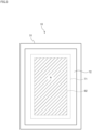
- Fig. 3 shows one cell 10 viewed in the stacking direction from the anode side.
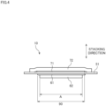
- Fig. 4 is a sectional view of the cell 10.
- Each of the electrolyte membrane 51, the first catalyst layer 61, the first gas diffusion layer 62, the second catalyst layer 71, and the porous transport layer 72 has a rectangular shape in a state viewed in the stacking direction.
- an outer edge of the first catalyst layer 61 is arranged at a more inward position than an outer edge of the electrolyte membrane 51.
- the area of the first catalyst layer 61 is smaller than that of the electrolyte membrane 51.
- an outer edge of the second catalyst layer 71 is arranged at a more inward position than the outer edge of the electrolyte membrane 51.
- the area of the second catalyst layer 71 is smaller than that of the electrolyte membrane 51.
- the first catalyst layer 61 is a coating film formed by coating one of surfaces of the electrolyte membrane 51 with catalyst ink.
- the second catalyst layer 71 is a coating film formed by coating the other surface of the electrolyte membrane 51 with catalyst ink.
- a coating range is controlled in such a manner that the first catalyst layer 61 and the second catalyst layer 71 are formed at the substantially same position when viewed in the stacking direction.
- the first catalyst layer 61 and the second catalyst layer 71 have an overlapping region 90 where the first catalyst layer 61 and the second catalyst layer 71 overlap each other in a state viewed in the stacking direction.
- the first gas diffusion layer 62 is bonded to the surface of the first catalyst layer 61 on the opposite side to the electrolyte membrane 51.
- the first gas diffusion layer 62 covers the first catalyst layer 61 partially.
- An outer edge of the first gas diffusion layer 62 is arranged at a more inward position than the outer edge of the first catalyst layer 61.
- the porous transport layer 72 is bonded to the surface of the second catalyst layer 71 on the opposite side to the electrolyte membrane 51.
- the porous transport layer 72 covers the second catalyst layer 71.
- An outer edge of the porous transport layer 72 is arranged at a more outward position than the outer edge of the second catalyst layer 71.
- the above-described cell 10 has a region where the first catalyst layer 61, the first gas diffusion layer 62, the second catalyst layer 71, and the porous transport layer 72 overlap each other in the stacking direction, and this region is an effective region A to practically function as an electrode.
- the outer edge of the first gas diffusion layer 62 is arranged at a more inward position than the outer edge of the porous transport layer 72, the outer edge of the first catalyst layer 61, and the outer edge of the second catalyst layer 71.
- a region corresponding to the first gas diffusion layer 62 is the effective region A to practically function as an electrode.
- the outer edge of the first gas diffusion layer 62 is arranged at a more inward position than an outer edge of the overlapping region 90 where the first catalyst layer 61 and the second catalyst layer 71 overlap each other.
- the first gas diffusion layer 62 has a rectangular shape in a state viewed in the stacking direction. Furthermore, all the four sides of the outer edge of the first gas diffusion layer 62 are arranged at more inward positions than the outer edge of the porous transport layer 72, the outer edge of the first catalyst layer 61, and the outer edge of the second catalyst layer 71. Thus, it is possible to define the rectangular effective region A of the first catalyst layer 61 and the second catalyst layer 71 with high accuracy using the first gas diffusion layer 62.
- all the four sides of the rectangular first gas diffusion layer 62 are arranged at more inward positions than the outer edge of the porous transport layer 72, the outer edge of the first catalyst layer 61, and the outer edge of the second catalyst layer 71.
- only some of the four sides of the first gas diffusion layer 62 may be arranged at more inward positions than the outer edge of the porous transport layer 72, the outer edge of the first catalyst layer 61, and the outer edge of the second catalyst layer 71.
- only the two long sides or only the two short sides may be arranged at more inward positions than the outer edge of the porous transport layer 72, the outer edge of the first catalyst layer 61, and the outer edge of the second catalyst layer 71.
- the cell 10 discussed in the above-described preferred embodiment is used in the water electrolyzer 1.
- a structure comparable to that of the above-described preferred embodiment may be applied to the cell 10 used in a fuel cell.
- the porous transport layer 72 is replaced with a second gas diffusion layer.
- the second gas diffusion layer is formed using a porous base material (carbon paper) made of carbon, for example.
- carbon paper made of carbon
- the effective region A may be defined using the second gas diffusion layer.
- Fig. 5 is a sectional view of the cell 10 according to this modification.
- the outer edge of the first gas diffusion layer 62 is arranged at a more outward position than the outer edge of the first catalyst layer 61 and the outer edge of the second catalyst layer 71.
- An outer edge of the second gas diffusion layer 73 is arranged at a more inward position than the outer edge of the first gas diffusion layer 62, the outer edge of the first catalyst layer 61, and the outer edge of the second catalyst layer 71.
- a region corresponding to the second gas diffusion layer 73 is the effective region A to practically function as an electrode.
- the outer edge of the second gas diffusion layer 73 is arranged at a more inward position than the outer edge of the overlapping region 90 where the first catalyst layer 61 and the second catalyst layer 71 overlap each other.
- the second gas diffusion layer 73 has a rectangular shape in a state viewed in the stacking direction, all the four sides of the outer edge of the second gas diffusion layer 73 are desirably arranged at more inward positions than the outer edge of the first gas diffusion layer 62, the outer edge of the first catalyst layer 61, and the outer edge of the second catalyst layer 71. By doing so, it becomes possible to define the rectangular effective region A of the first catalyst layer 61 and the second catalyst layer 71 with high accuracy using the second gas diffusion layer 73.
- the cell 10 discussed in the above-described preferred embodiment uses a proton-exchange membrane as the electrolyte membrane 51.
- the electrode structure of the present invention may use an anion-exchange membrane as an electrolyte membrane.
- a structure comparable to that of the above-described preferred embodiment may be applied to an electrode structure used in a liquid organic hydrogen carrier (LOHC) process by which an aromatic compound such as toluene is hydrogenated to produce an organic hydride (toluene-methylcyclohexane, for example).
- LOHC liquid organic hydrogen carrier
Landscapes
- Chemical & Material Sciences (AREA)
- Chemical Kinetics & Catalysis (AREA)
- Electrochemistry (AREA)
- Engineering & Computer Science (AREA)
- Materials Engineering (AREA)
- Metallurgy (AREA)
- Organic Chemistry (AREA)
- General Chemical & Material Sciences (AREA)
- Manufacturing & Machinery (AREA)
- Life Sciences & Earth Sciences (AREA)
- Sustainable Development (AREA)
- Sustainable Energy (AREA)
- Composite Materials (AREA)
- Inorganic Chemistry (AREA)
- Fuel Cell (AREA)
- Inert Electrodes (AREA)
- Electrodes For Compound Or Non-Metal Manufacture (AREA)
- Electrolytic Production Of Non-Metals, Compounds, Apparatuses Therefor (AREA)
Abstract
Description
- The present invention relates to an electrode structure.
- In a solid polymer water electrolyzer conventionally known, hydrogen (H2) is produced by electrolysis of water (H2O). The solid polymer water electrolyzer has a cell stack with cells and separators stacked alternately. Each of the cells includes an electrolyte membrane, and a catalyst layer formed on each of both sides of the electrolyte membrane. During use of the solid polymer water electrolyzer, a voltage is applied between an anode-side catalyst layer and a cathode-side catalyst layer and water is supplied to the anode-side catalyst layer. This causes electrochemical reactions as follows in the anode-side catalyst layer and the cathode-side catalyst layer. As a result, hydrogen is output from the cathode-side catalyst layer.
(anode side) 2H2O → 4H+ + O2 + 4e-
(cathode side) 2H+ + 2e- → H2
- The conventional solid polymer water electrolyzer is described in
Japanese Patent Application Laid-Open No. 2022-023996 - In the conventional solid polymer water electrolyzer, the catalyst layer is entirely used as an electrode. However, if a formation range of the catalyst layer relative to the electrolyte membrane is determined with low accuracy, using the catalyst layer entirely as an electrode causes fluctuation of an effective region to practically function as an electrode. The same problem might occur not only in the cell of the solid polymer water electrolyzer but also in a cell of a solid polymer fuel cell.
- The present invention is intended to provide a technique that achieves reduction in fluctuation of an effective region to function as an electrode even if a formation range of a catalyst layer is determined with low accuracy.
- A first aspect of the present invention is intended for an electrode structure comprising: an electrolyte membrane; a first catalyst layer formed on one of surfaces of the electrolyte membrane; a first gas diffusion layer stacked on a surface of the first catalyst layer; a second catalyst layer formed on the other surface of the electrolyte membrane; and a porous transport layer or a second gas diffusion layer stacked on a surface of the second catalyst layer. An outer edge of the first gas diffusion layer is arranged at a more inward position than an outer edge of the porous transport layer or the second gas diffusion layer, an outer edge of the first catalyst layer, and an outer edge of the second catalyst layer.
- According to the first aspect of the present invention, an effective region of the first catalyst layer and the second catalyst layer is defined using the first gas diffusion layer. By doing so, even if formation ranges of the first catalyst layer and the second catalyst layer are determined with low accuracy, it still becomes possible to reduce fluctuation of the effective region to function as an electrode.
- In a state viewed in a stacking direction, the first catalyst layer and the second catalyst layer may have an overlapping region where the first catalyst layer and the second catalyst layer overlap each other and the outer edge of the first catalyst layer and the outer edge of the second catalyst layer may be at positions differing from each other, and the outer edge of the first gas diffusion layer may be arranged at a more inward position than an outer edge of the overlapping region.
- By doing so, irrespective of a difference between the positions of the first catalyst layer and the second catalyst layer, it becomes possible to define the effective region of the first catalyst layer and the second catalyst layer using the first gas diffusion layer.
- In a state viewed in a stacking direction, the first gas diffusion layer may have a rectangular shape and all the four sides of the outer edge of the first gas diffusion layer may be arranged at more inward positions than the outer edge of the porous transport layer or the second gas diffusion layer, the outer edge of the first catalyst layer, and the outer edge of the second catalyst layer.
- By doing so, it becomes possible to define the rectangular effective region of the first catalyst layer and the second catalyst layer with high accuracy using the first gas diffusion layer.
- A second aspect of the present invention is intended for an electrode structure comprising: an electrolyte membrane; a first catalyst layer formed on one of surfaces of the electrolyte membrane; a first gas diffusion layer stacked on a surface of the first catalyst layer; a second catalyst layer formed on the other surface of the electrolyte membrane; and a second gas diffusion layer stacked on a surface of the second catalyst layer. A outer edge of the second gas diffusion layer is arranged at a more inward position than an outer edge of the first gas diffusion layer, an outer edge of the first catalyst layer, and an outer edge of the second catalyst layer.
- According to the second aspect of the present invention, an effective region of the first catalyst layer and the second catalyst layer is defined using the second gas diffusion layer. By doing so, even if formation ranges of the first catalyst layer and the second catalyst layer are determined with low accuracy, it still becomes possible to reduce fluctuation of the effective region to function as an electrode.
- In a state viewed in a stacking direction, the first catalyst layer and the second catalyst layer may have an overlapping region where the first catalyst layer and the second catalyst layer overlap each other and the outer edge of the first catalyst layer and the outer edge of the second catalyst layer may be at positions differing from each other, and the outer edge of the second gas diffusion layer may be arranged at a more inward position than an outer edge of the overlapping region.
- By doing so, irrespective of a difference between the positions of the first catalyst layer and the second catalyst layer, it becomes possible to define the effective region of the first catalyst layer and the second catalyst layer using the second gas diffusion layer.
- In a state viewed in a stacking direction, the second gas diffusion layer may have a rectangular shape and all the four sides of the outer edge of the second gas diffusion layer may be arranged at more inward positions than the outer edge of the first gas diffusion layer, the outer edge of the first catalyst layer, and the outer edge of the second catalyst layer.
- By doing so, it becomes possible to define the rectangular effective region of the first catalyst layer and the second catalyst layer with high accuracy using the second gas diffusion layer.
- The first catalyst layer and the second catalyst layer may be coating films.
- These and other objects, features, aspects and advantages of the present invention will become more apparent from the following detailed description of the present invention when taken in conjunction with the accompanying drawings.
-
-
Fig. 1 is a schematic view of a water electrolyzer; -
Fig. 2 is a schematic view showing one cell and separators in a pair arranged on both sides of the cell; -
Fig. 3 shows an electrode structure viewed in a stacking direction from an anode side; -
Fig. 4 is a sectional view of the electrode structure; and -
Fig. 5 is a sectional view of an electrode structure according to a modification. - A preferred embodiment of the present invention will be described below by referring to the drawings.
-
Fig. 1 is a schematic view of a water electrolyzer 1. The water electrolyzer 1 is to produce hydrogen by solid polymer water electrolysis. As shown inFig. 1 , the water electrolyzer 1 includes acell stack 30 with a plurality ofcells 10 and a plurality ofseparators 20, and apower supply 40. Thecells 10 and theseparators 20 are stacked alternately to form thecell stack 30. In the following, a direction in which thecells 10 and theseparators 20 are stacked will be called a "stacking direction." -
Fig. 2 schematically shows only onecell 10 andseparators 20 in a pair arranged on both sides of thiscell 10 that form thecell stack 30 of the water electrolyzer 1. As shown inFig. 2 , onecell 10 includes anelectrolyte membrane 51, afirst catalyst layer 61, a firstgas diffusion layer 62, asecond catalyst layer 71, and aporous transport layer 72. - A stacked body composed of the
electrolyte membrane 51, thefirst catalyst layer 61, the firstgas diffusion layer 62, thesecond catalyst layer 71, and theporous transport layer 72 is called a membrane-electrode-assembly (EMA). A stacked body composed of theelectrolyte membrane 51, thefirst catalyst layer 61, and thesecond catalyst layer 71 is called a catalyst-coated membrane (CCM). - The
electrolyte membrane 51 is a membrane having ion conductivity (ion-exchange membrane). Theelectrolyte membrane 51 of the present preferred embodiment is a proton-exchange membrane that conducts hydrogen ions (H+). A fluorine-based or hydrocarbon-based polymer electrolyte membrane is used as theelectrolyte membrane 51. More specifically, a polymer electrolyte membrane containing perfluorocarbon sulfonic acid is used as theelectrolyte membrane 51, for example. Theelectrolyte membrane 51 has a thickness from 5 to 200 µm, for example. - The
first catalyst layer 61 is a catalyst layer that causes electrochemical reaction on a cathode side. Thefirst catalyst layer 61 is formed on a cathode-side surface of theelectrolyte membrane 51. Thefirst catalyst layer 61 contains a large number of carbon particles on which catalyst particles are supported. The catalyst particles are particles of platinum, for example. Alternatively, the catalyst particles may be prepared by mixing particles of a tiny amount of ruthenium or cobalt into particles of platinum. During use of the water electrolyzer 1, hydrogen ions (H+) and electrons (e-) are supplied to thefirst catalyst layer 61. Then, thepower supply 40 applies a voltage between thefirst catalyst layer 61 and thesecond catalyst layer 71. By doing so, by the actions of the applied voltage and the catalyst particles, a reduction reaction is caused in thefirst catalyst layer 61 to generate hydrogen gas (H2) from the hydrogen ions and the electrons. - The first
gas diffusion layer 62 is a layer for transporting electrons from theseparator 20 to thefirst catalyst layer 61 and for transporting hydrogen generated in thefirst catalyst layer 61 to theseparator 20. The firstgas diffusion layer 62 is stacked on an external surface of the first catalyst layer 61 (a surface on the opposite side to the electrolyte membrane 51). Thefirst catalyst layer 61 is interposed between theelectrolyte membrane 51 and the firstgas diffusion layer 62. The firstgas diffusion layer 62 is made of a material having electrical conductivity and porosity. The firstgas diffusion layer 62 is formed using a porous base material (carbon paper) made of carbon, for example. - The
second catalyst layer 71 is a catalyst layer that causes electrochemical reaction on an anode side. Thesecond catalyst layer 71 is formed on an anode-side surface of the electrolyte membrane 51 (a surface on the opposite side to the first catalyst layer 61). Thesecond catalyst layer 71 contains a large number of catalyst particles. The catalyst particles are particles of iridium oxide (IrOx), platinum (Pt), an alloy of iridium (Ir) and ruthenium (Ru), or an alloy of iridium (Ir) and titanium dioxide (TiO2), for example. During use of the water electrolyzer 1, water (H2O) is supplied to thesecond catalyst layer 71. Then, thepower supply 40 applies a voltage between thefirst catalyst layer 61 and thesecond catalyst layer 71. By doing so, by the actions of the applied voltage and the catalyst particles, the water is electrolyzed into hydrogen ions (H+), oxygen (O2), and electrons (e-) in thesecond catalyst layer 71. - The
porous transport layer 72 is a layer for supplying water uniformly to thesecond catalyst layer 71 and for transporting oxygen and electrons generated in thesecond catalyst layer 71 to theseparator 20. Theporous transport layer 72 is stacked on an external surface of the second catalyst layer 71 (a surface on the opposite side to the electrolyte membrane 51). Thesecond catalyst layer 71 is interposed between theelectrolyte membrane 51 and theporous transport layer 72. Theporous transport layer 72 is made of a material having electrical conductivity and porosity. Theporous transport layer 72 is formed using a porous base material made of metal such as titanium or stainless steel, for example. - The
separator 20 is a layer for moving electrons between thecells 10 next to each other and for forming a passage for water, oxygen, and hydrogen. Theseparator 20 is interposed between the firstgas diffusion layer 62 of onecell 10 and theporous transport layer 72 of thecell 10 next to the onecell 10. Theseparator 20 is composed of ametal plate 21 having electrical conductivity and impermeable to gas and liquid. Themetal plate 21 has acathode surface 22 contacting the firstgas diffusion layer 62, and an anode surface 23 contacting theporous transport layer 72. - The
metal plate 21 has a plurality ofcathode grooves 24 formed at thecathode surface 22. Hydrogen generated in thefirst catalyst layer 61 passes through the firstgas diffusion layer 62 and is then output to the outside through thecathode grooves 24 of theseparator 20. - The
metal plate 21 has a plurality ofanode grooves 25 formed at the anode surface 23. Water is supplied to theporous transport layer 72 through theanode grooves 25 of theseparator 20. Oxygen generated in thesecond catalyst layer 71 passes through theporous transport layer 72 and is then output to the outside through theanode grooves 25 of theseparator 20. - The
power supply 40 is a device that applies a voltage to thecell stack 30. As shown inFig. 1 , thepower supply 40 has a positive terminal electrically connected to theseparator 20 at an end portion of thecell stack 30 farthest on the anode side. Thepower supply 40 has a negative terminal electrically connected to theseparator 20 at an end portion of thecell stack 30 farthest on the cathode side. Thepower supply 40 applies a voltage to thecell stack 30 necessary for electrolysis of water. - During use of the water electrolyzer 1, water is supplied from the
anode grooves 25 of theseparator 20 to thesecond catalyst layer 71 through theporous transport layer 72. Then, by the actions of a voltage applied from thepower supply 40 and the catalyst particles in thesecond catalyst layer 71, the water is decomposed into hydrogen ions, oxygen, and electrons. The hydrogen ions propagate through theelectrolyte membrane 51 into thefirst catalyst layer 61. The oxygen passes through theporous transport layer 72 and theanode grooves 25 of theseparator 20 and is then output to the outside. The electrons pass through theporous transport layer 72 and theseparator 20 and then flow into the adjoiningcell 10. In the adjoiningcell 10, these electrons pass through the firstgas diffusion layer 62 to reach thefirst catalyst layer 61. Then, the hydrogen ions and the electrons are combined with each other to generate hydrogen in thefirst catalyst layer 61. The generated hydrogen passes through the firstgas diffusion layer 62 and thecathode grooves 24 of theseparator 20 and is then output to the outside. In this way, hydrogen is produced. - As described above, the
cell 10 is an "electrode structure" having a function as an electrode. The configuration of thecell 10 will be described below in more detail. -
Fig. 3 shows onecell 10 viewed in the stacking direction from the anode side.Fig. 4 is a sectional view of thecell 10. - Each of the
electrolyte membrane 51, thefirst catalyst layer 61, the firstgas diffusion layer 62, thesecond catalyst layer 71, and theporous transport layer 72 has a rectangular shape in a state viewed in the stacking direction. As shown inFig. 4 , an outer edge of thefirst catalyst layer 61 is arranged at a more inward position than an outer edge of theelectrolyte membrane 51. Thus, in a state viewed in the stacking direction, the area of thefirst catalyst layer 61 is smaller than that of theelectrolyte membrane 51. As shown inFig. 4 , an outer edge of thesecond catalyst layer 71 is arranged at a more inward position than the outer edge of theelectrolyte membrane 51. Thus, in a state viewed in the stacking direction, the area of thesecond catalyst layer 71 is smaller than that of theelectrolyte membrane 51. - The
first catalyst layer 61 is a coating film formed by coating one of surfaces of theelectrolyte membrane 51 with catalyst ink. Thesecond catalyst layer 71 is a coating film formed by coating the other surface of theelectrolyte membrane 51 with catalyst ink. During coating with the catalyst ink, a coating range is controlled in such a manner that thefirst catalyst layer 61 and thesecond catalyst layer 71 are formed at the substantially same position when viewed in the stacking direction. Thus, thefirst catalyst layer 61 and thesecond catalyst layer 71 have anoverlapping region 90 where thefirst catalyst layer 61 and thesecond catalyst layer 71 overlap each other in a state viewed in the stacking direction. Meanwhile, it is extremely difficult to make an exact match between ranges of coating of the both surfaces of theelectrolyte membrane 51 with the catalyst ink. This causes a slight difference between the position of the outer edge of thefirst catalyst layer 61 and the position of the outer edge of thesecond catalyst layer 71, as shown inFig. 4 . In some cases, in a state viewed in the stacking direction, the area of thefirst catalyst layer 61 and that of thesecond catalyst layer 71 are not exactly the same. - The first
gas diffusion layer 62 is bonded to the surface of thefirst catalyst layer 61 on the opposite side to theelectrolyte membrane 51. The firstgas diffusion layer 62 covers thefirst catalyst layer 61 partially. An outer edge of the firstgas diffusion layer 62 is arranged at a more inward position than the outer edge of thefirst catalyst layer 61. Theporous transport layer 72 is bonded to the surface of thesecond catalyst layer 71 on the opposite side to theelectrolyte membrane 51. Theporous transport layer 72 covers thesecond catalyst layer 71. An outer edge of theporous transport layer 72 is arranged at a more outward position than the outer edge of thesecond catalyst layer 71. - The above-described
cell 10 has a region where thefirst catalyst layer 61, the firstgas diffusion layer 62, thesecond catalyst layer 71, and theporous transport layer 72 overlap each other in the stacking direction, and this region is an effective region A to practically function as an electrode. - In the
cell 10 of the present preferred embodiment, the outer edge of the firstgas diffusion layer 62 is arranged at a more inward position than the outer edge of theporous transport layer 72, the outer edge of thefirst catalyst layer 61, and the outer edge of thesecond catalyst layer 71. Thus, in the present preferred embodiment, a region corresponding to the firstgas diffusion layer 62 is the effective region A to practically function as an electrode. Specifically, it is possible to define the effective region A of thefirst catalyst layer 61 and thesecond catalyst layer 71 using the firstgas diffusion layer 62. By doing so, even if formation ranges of thefirst catalyst layer 61 and thesecond catalyst layer 71 are determined with low accuracy, it still becomes possible to reduce fluctuation of the effective region A to function as an electrode. - In particular, if the
first catalyst layer 61 and thesecond catalyst layer 71 are coating films, a slight difference is caused between the position of the outer edge of thefirst catalyst layer 61 and the position of the outer edge of thesecond catalyst layer 71, as described above. In this regard, in the present preferred embodiment, the outer edge of the firstgas diffusion layer 62 is arranged at a more inward position than an outer edge of the overlappingregion 90 where thefirst catalyst layer 61 and thesecond catalyst layer 71 overlap each other. Thus, irrespective of a difference between the positions of thefirst catalyst layer 61 and thesecond catalyst layer 71, it is possible to define the effective region A of thefirst catalyst layer 61 and thesecond catalyst layer 71 using the firstgas diffusion layer 62. - In the present preferred embodiment, the first
gas diffusion layer 62 has a rectangular shape in a state viewed in the stacking direction. Furthermore, all the four sides of the outer edge of the firstgas diffusion layer 62 are arranged at more inward positions than the outer edge of theporous transport layer 72, the outer edge of thefirst catalyst layer 61, and the outer edge of thesecond catalyst layer 71. Thus, it is possible to define the rectangular effective region A of thefirst catalyst layer 61 and thesecond catalyst layer 71 with high accuracy using the firstgas diffusion layer 62. - While one preferred embodiment of the present invention has been described above, the present invention is not limited to the above-described preferred embodiment. The following describes various modifications by mainly showing differences from the above-described preferred embodiment.
- In the above-described preferred embodiment, all the four sides of the rectangular first
gas diffusion layer 62 are arranged at more inward positions than the outer edge of theporous transport layer 72, the outer edge of thefirst catalyst layer 61, and the outer edge of thesecond catalyst layer 71. In another case, only some of the four sides of the firstgas diffusion layer 62 may be arranged at more inward positions than the outer edge of theporous transport layer 72, the outer edge of thefirst catalyst layer 61, and the outer edge of thesecond catalyst layer 71. For example, of the two long sides and the two short sides of the firstgas diffusion layer 62 shown inFig. 3 , only the two long sides or only the two short sides may be arranged at more inward positions than the outer edge of theporous transport layer 72, the outer edge of thefirst catalyst layer 61, and the outer edge of thesecond catalyst layer 71. - The
cell 10 discussed in the above-described preferred embodiment is used in the water electrolyzer 1. However, a structure comparable to that of the above-described preferred embodiment may be applied to thecell 10 used in a fuel cell. In the case of thecell 10 for a fuel cell, theporous transport layer 72 is replaced with a second gas diffusion layer. The second gas diffusion layer is formed using a porous base material (carbon paper) made of carbon, for example. Even in this case, it is still possible to define the effective region A as an electrode using the firstgas diffusion layer 62 by arranging the outer edge of the firstgas diffusion layer 62 at a more inward position than an outer edge of the second gas diffusion layer, the outer edge of thefirst catalyst layer 61, and the outer edge of thesecond catalyst layer 71. - In the case of the
cell 10 for a fuel cell, the effective region A may be defined using the second gas diffusion layer.Fig. 5 is a sectional view of thecell 10 according to this modification. In the illustration inFig. 5 , the outer edge of the firstgas diffusion layer 62 is arranged at a more outward position than the outer edge of thefirst catalyst layer 61 and the outer edge of thesecond catalyst layer 71. An outer edge of the secondgas diffusion layer 73 is arranged at a more inward position than the outer edge of the firstgas diffusion layer 62, the outer edge of thefirst catalyst layer 61, and the outer edge of thesecond catalyst layer 71. Thus, in the illustration inFig. 5 , a region corresponding to the secondgas diffusion layer 73 is the effective region A to practically function as an electrode. Specifically, it is possible to define the effective region A of thefirst catalyst layer 61 and thesecond catalyst layer 71 using the secondgas diffusion layer 73. By doing so, even if formation ranges of thefirst catalyst layer 61 and thesecond catalyst layer 71 are determined with low accuracy, it still becomes possible to reduce fluctuation of the effective region A to function as an electrode. - In particular, in the illustration in
Fig. 5 , the outer edge of the secondgas diffusion layer 73 is arranged at a more inward position than the outer edge of the overlappingregion 90 where thefirst catalyst layer 61 and thesecond catalyst layer 71 overlap each other. Thus, irrespective of a difference between the positions of thefirst catalyst layer 61 and thesecond catalyst layer 71, it is possible to define the effective region A of thefirst catalyst layer 61 and thesecond catalyst layer 71 using the secondgas diffusion layer 73. - If the second
gas diffusion layer 73 has a rectangular shape in a state viewed in the stacking direction, all the four sides of the outer edge of the secondgas diffusion layer 73 are desirably arranged at more inward positions than the outer edge of the firstgas diffusion layer 62, the outer edge of thefirst catalyst layer 61, and the outer edge of thesecond catalyst layer 71. By doing so, it becomes possible to define the rectangular effective region A of thefirst catalyst layer 61 and thesecond catalyst layer 71 with high accuracy using the secondgas diffusion layer 73. - The
cell 10 discussed in the above-described preferred embodiment uses a proton-exchange membrane as theelectrolyte membrane 51. However, the electrode structure of the present invention may use an anion-exchange membrane as an electrolyte membrane. - A structure comparable to that of the above-described preferred embodiment may be applied to an electrode structure used in a liquid organic hydrogen carrier (LOHC) process by which an aromatic compound such as toluene is hydrogenated to produce an organic hydride (toluene-methylcyclohexane, for example).
- Some of the structures shown in the above-described preferred embodiment or modifications may be deleted or other structures may be added within a scope not deviating from the purport of the present invention.
- While the invention has been shown and described in detail, the foregoing description is in all aspects illustrative and not restrictive. It is therefore understood that numerous modifications and variations can be devised without departing from the scope of the invention.
Claims (7)
- An electrode structure comprising:an electrolyte membrane (51);a first catalyst layer (61) formed on one of surfaces of said electrolyte membrane (51);a first gas diffusion layer (62) stacked on a surface of said first catalyst layer (61);a second catalyst layer (71) formed on the other surface of said electrolyte membrane (51); anda porous transport layer (72) or a second gas diffusion layer stacked on a surface of said second catalyst layer (71), whereinan outer edge of said first gas diffusion layer (62) is arranged at a more inward position than an outer edge of said porous transport layer (72) or said second gas diffusion layer, an outer edge of said first catalyst layer (61), and an outer edge of said second catalyst layer (71).
- The electrode structure according to claim 1, whereinin a state viewed in a stacking direction, said first catalyst layer (61) and said second catalyst layer (71) have an overlapping region (90) where said first catalyst layer (61) and said second catalyst layer (71) overlap each other and the outer edge of said first catalyst layer (61) and the outer edge of said second catalyst layer (71) are at positions differing from each other, andthe outer edge of said first gas diffusion layer (62) is arranged at a more inward position than an outer edge of said overlapping region (90).
- The electrode structure according to claim 1 or 2, wherein
in a state viewed in a stacking direction, said first gas diffusion layer (62) has a rectangular shape and all the four sides of the outer edge of the first gas diffusion layer (62) are arranged at more inward positions than the outer edge of said porous transport layer (72) or said second gas diffusion layer, the outer edge of said first catalyst layer (61), and the outer edge of said second catalyst layer (71). - An electrode structure comprising:an electrolyte membrane (51);a first catalyst layer (61) formed on one of surfaces of said electrolyte membrane (51);a first gas diffusion layer (62) stacked on a surface of said first catalyst layer (61);a second catalyst layer (71) formed on the other surface of said electrolyte membrane (51); anda second gas diffusion layer (73) stacked on a surface of said second catalyst layer (71), whereinan outer edge of said second gas diffusion layer (73) is arranged at a more inward position than an outer edge of said first gas diffusion layer (62), an outer edge of said first catalyst layer (61), and an outer edge of said second catalyst layer (71).
- The electrode structure according to claim 4, whereinin a state viewed in a stacking direction, said first catalyst layer (61) and said second catalyst layer (71) have an overlapping region (90) where said first catalyst layer (61) and said second catalyst layer (71) overlap each other and the outer edge of said first catalyst layer (61) and the outer edge of said second catalyst layer (71) are at positions differing from each other, andthe outer edge of said second gas diffusion layer (73) is arranged at a more inward position than an outer edge of said overlapping region (90).
- The electrode structure according to claim 4 or 5, wherein
in a state viewed in a stacking direction, said second gas diffusion layer (73) has a rectangular shape and all the four sides of the outer edge of the second gas diffusion layer (73) are arranged at more inward positions than the outer edge of said first gas diffusion layer (62), the outer edge of said first catalyst layer (61), and the outer edge of said second catalyst layer (71). - The electrode structure according to any one of claims 1 to 6, wherein
said first catalyst layer (61) and said second catalyst layer (71) are coating films.
Applications Claiming Priority (1)
| Application Number | Priority Date | Filing Date | Title |
|---|---|---|---|
| JP2023155639A JP2025047250A (en) | 2023-09-21 | 2023-09-21 | Electrode Structure |
Publications (2)
| Publication Number | Publication Date |
|---|---|
| EP4534729A2 true EP4534729A2 (en) | 2025-04-09 |
| EP4534729A3 EP4534729A3 (en) | 2025-04-30 |
Family
ID=92108277
Family Applications (1)
| Application Number | Title | Priority Date | Filing Date |
|---|---|---|---|
| EP24191367.2A Pending EP4534729A3 (en) | 2023-09-21 | 2024-07-29 | Electrode structure |
Country Status (5)
| Country | Link |
|---|---|
| US (1) | US20250101612A1 (en) |
| EP (1) | EP4534729A3 (en) |
| JP (1) | JP2025047250A (en) |
| CN (1) | CN119663328A (en) |
| AU (1) | AU2024205774B2 (en) |
Citations (1)
| Publication number | Priority date | Publication date | Assignee | Title |
|---|---|---|---|---|
| JP2022023996A (en) | 2021-11-05 | 2022-02-08 | 東京瓦斯株式会社 | Electrochemical device |
Family Cites Families (4)
| Publication number | Priority date | Publication date | Assignee | Title |
|---|---|---|---|---|
| JP5681792B2 (en) * | 2011-04-01 | 2015-03-11 | 本田技研工業株式会社 | ELECTROLYTE MEMBRANE / ELECTRODE STRUCTURE FOR FUEL CELL AND METHOD FOR PRODUCING THE SAME |
| JP6158758B2 (en) * | 2014-06-30 | 2017-07-05 | 本田技研工業株式会社 | Electrolyte membrane / electrode structure with resin frame for fuel cells |
| JP6659770B2 (en) * | 2018-06-08 | 2020-03-04 | 本田技研工業株式会社 | Fuel cell stack |
| JP6715277B2 (en) * | 2018-03-15 | 2020-07-01 | 本田技研工業株式会社 | Fuel cell stack and dummy cell for fuel cell stack |
-
2023
- 2023-09-21 JP JP2023155639A patent/JP2025047250A/en active Pending
-
2024
- 2024-07-29 EP EP24191367.2A patent/EP4534729A3/en active Pending
- 2024-08-15 AU AU2024205774A patent/AU2024205774B2/en active Active
- 2024-09-17 US US18/887,420 patent/US20250101612A1/en active Pending
- 2024-09-18 CN CN202411299451.XA patent/CN119663328A/en active Pending
Patent Citations (1)
| Publication number | Priority date | Publication date | Assignee | Title |
|---|---|---|---|---|
| JP2022023996A (en) | 2021-11-05 | 2022-02-08 | 東京瓦斯株式会社 | Electrochemical device |
Also Published As
| Publication number | Publication date |
|---|---|
| CN119663328A (en) | 2025-03-21 |
| AU2024205774A1 (en) | 2025-04-10 |
| AU2024205774B2 (en) | 2026-02-26 |
| JP2025047250A (en) | 2025-04-03 |
| US20250101612A1 (en) | 2025-03-27 |
| EP4534729A3 (en) | 2025-04-30 |
Similar Documents
| Publication | Publication Date | Title |
|---|---|---|
| EP2612390B1 (en) | Assembly for reversible fuel cell | |
| EP4516967A1 (en) | Membrane electrode assembly, electrolysis cell, electrolysis device, and method for producing membrane electrode assembly | |
| KR20040099149A (en) | Fuel Cell | |
| EP4343031A2 (en) | Separator and water electrolyzer | |
| EP4343030A2 (en) | Water electrolyzer | |
| US20110139610A1 (en) | Thin Film Catalyst on Porous Media and Electrochemical Cell Employing the Same | |
| KR20140133301A (en) | The membrane electrdoe assembly for an electrochemical cell | |
| EP4534729A2 (en) | Electrode structure | |
| US20240110299A1 (en) | Support, electrode, membrane electrode assembly, electrochemical cell, stack, and electrolyzer | |
| EP4534731A2 (en) | Electrode structure | |
| US20250101611A1 (en) | Electrode structure | |
| EP4435146A2 (en) | Electrode structure and water electrolyzer | |
| EP4442861A1 (en) | Electrode structure and water electrolyzer | |
| EP4610403A1 (en) | Membrane electrode assembly and method for manufacturing membrane electrode assembly | |
| US12540412B2 (en) | Water electrolysis cell, method of producing water electrolysis cell | |
| JP2006185882A (en) | Operation method of fuel cell using metal separator, and power generator having fuel cell using metal separator | |
| US20240178427A1 (en) | Solid oxide cell | |
| CN116472625A (en) | Improvement of Durability of Fuel Cell Metal Bipolar Plates |
Legal Events
| Date | Code | Title | Description |
|---|---|---|---|
| PUAI | Public reference made under article 153(3) epc to a published international application that has entered the european phase |
Free format text: ORIGINAL CODE: 0009012 |
|
| STAA | Information on the status of an ep patent application or granted ep patent |
Free format text: STATUS: THE APPLICATION HAS BEEN PUBLISHED |
|
| PUAL | Search report despatched |
Free format text: ORIGINAL CODE: 0009013 |
|
| AK | Designated contracting states |
Kind code of ref document: A2 Designated state(s): AL AT BE BG CH CY CZ DE DK EE ES FI FR GB GR HR HU IE IS IT LI LT LU LV MC ME MK MT NL NO PL PT RO RS SE SI SK SM TR |
|
| AK | Designated contracting states |
Kind code of ref document: A3 Designated state(s): AL AT BE BG CH CY CZ DE DK EE ES FI FR GB GR HR HU IE IS IT LI LT LU LV MC ME MK MT NL NO PL PT RO RS SE SI SK SM TR |
|
| RIC1 | Information provided on ipc code assigned before grant |
Ipc: H01M 8/1004 20160101ALI20250327BHEP Ipc: H01M 4/88 20060101ALI20250327BHEP Ipc: H01M 4/86 20060101ALI20250327BHEP Ipc: C25B 13/00 20060101ALI20250327BHEP Ipc: C25B 11/03 20210101ALI20250327BHEP Ipc: C25B 1/04 20210101AFI20250327BHEP |
|
| STAA | Information on the status of an ep patent application or granted ep patent |
Free format text: STATUS: REQUEST FOR EXAMINATION WAS MADE |
|
| 17P | Request for examination filed |
Effective date: 20251014 |
|
| GRAP | Despatch of communication of intention to grant a patent |
Free format text: ORIGINAL CODE: EPIDOSNIGR1 |
|
| STAA | Information on the status of an ep patent application or granted ep patent |
Free format text: STATUS: GRANT OF PATENT IS INTENDED |
|
| RIC1 | Information provided on ipc code assigned before grant |
Ipc: C25B 1/04 20210101AFI20260126BHEP Ipc: C25B 9/75 20210101ALI20260126BHEP Ipc: C25B 9/77 20210101ALI20260126BHEP Ipc: C25B 11/032 20210101ALI20260126BHEP Ipc: H01M 4/86 20060101ALI20260126BHEP Ipc: H01M 4/88 20060101ALI20260126BHEP Ipc: H01M 8/1004 20160101ALI20260126BHEP Ipc: H01M 8/0245 20160101ALI20260126BHEP |
|
| INTG | Intention to grant announced |
Effective date: 20260206 |