EP4534749A2 - Wäschebehandlungsvorrichtung - Google Patents
Wäschebehandlungsvorrichtung Download PDFInfo
- Publication number
- EP4534749A2 EP4534749A2 EP25158800.0A EP25158800A EP4534749A2 EP 4534749 A2 EP4534749 A2 EP 4534749A2 EP 25158800 A EP25158800 A EP 25158800A EP 4534749 A2 EP4534749 A2 EP 4534749A2
- Authority
- EP
- European Patent Office
- Prior art keywords
- arm
- treating apparatus
- drum
- laundry treating
- hub
- Prior art date
- Legal status (The legal status is an assumption and is not a legal conclusion. Google has not performed a legal analysis and makes no representation as to the accuracy of the status listed.)
- Pending
Links
Images




Classifications
-
- D—TEXTILES; PAPER
- D06—TREATMENT OF TEXTILES OR THE LIKE; LAUNDERING; FLEXIBLE MATERIALS NOT OTHERWISE PROVIDED FOR
- D06F—LAUNDERING, DRYING, IRONING, PRESSING OR FOLDING TEXTILE ARTICLES
- D06F37/00—Details specific to washing machines covered by groups D06F21/00 - D06F25/00
- D06F37/02—Rotary receptacles, e.g. drums
- D06F37/04—Rotary receptacles, e.g. drums adapted for rotation or oscillation about a horizontal or inclined axis
-
- D—TEXTILES; PAPER
- D06—TREATMENT OF TEXTILES OR THE LIKE; LAUNDERING; FLEXIBLE MATERIALS NOT OTHERWISE PROVIDED FOR
- D06F—LAUNDERING, DRYING, IRONING, PRESSING OR FOLDING TEXTILE ARTICLES
- D06F37/00—Details specific to washing machines covered by groups D06F21/00 - D06F25/00
- D06F37/26—Casings; Tubs
- D06F37/264—Tubs provided with reinforcing structures, e.g. ribs, inserts, braces
-
- D—TEXTILES; PAPER
- D06—TREATMENT OF TEXTILES OR THE LIKE; LAUNDERING; FLEXIBLE MATERIALS NOT OTHERWISE PROVIDED FOR
- D06F—LAUNDERING, DRYING, IRONING, PRESSING OR FOLDING TEXTILE ARTICLES
- D06F21/00—Washing machines with receptacles, e.g. perforated, having a rotary movement, e.g. oscillatory movement
- D06F21/02—Washing machines with receptacles, e.g. perforated, having a rotary movement, e.g. oscillatory movement about a horizontal axis
- D06F21/04—Washing machines with receptacles, e.g. perforated, having a rotary movement, e.g. oscillatory movement about a horizontal axis within an enclosing receptacle
-
- D—TEXTILES; PAPER
- D06—TREATMENT OF TEXTILES OR THE LIKE; LAUNDERING; FLEXIBLE MATERIALS NOT OTHERWISE PROVIDED FOR
- D06F—LAUNDERING, DRYING, IRONING, PRESSING OR FOLDING TEXTILE ARTICLES
- D06F25/00—Washing machines with receptacles, e.g. perforated, having a rotary movement, e.g. oscillatory movement, the receptacle serving both for washing and for centrifugally separating water from the laundry and having further drying means, e.g. using hot air
-
- D—TEXTILES; PAPER
- D06—TREATMENT OF TEXTILES OR THE LIKE; LAUNDERING; FLEXIBLE MATERIALS NOT OTHERWISE PROVIDED FOR
- D06F—LAUNDERING, DRYING, IRONING, PRESSING OR FOLDING TEXTILE ARTICLES
- D06F37/00—Details specific to washing machines covered by groups D06F21/00 - D06F25/00
- D06F37/20—Mountings, e.g. resilient mountings, for the rotary receptacle, motor, tub or casing; Preventing or damping vibrations
- D06F37/22—Mountings, e.g. resilient mountings, for the rotary receptacle, motor, tub or casing; Preventing or damping vibrations in machines with a receptacle rotating or oscillating about a horizontal axis
-
- D—TEXTILES; PAPER
- D06—TREATMENT OF TEXTILES OR THE LIKE; LAUNDERING; FLEXIBLE MATERIALS NOT OTHERWISE PROVIDED FOR
- D06F—LAUNDERING, DRYING, IRONING, PRESSING OR FOLDING TEXTILE ARTICLES
- D06F37/00—Details specific to washing machines covered by groups D06F21/00 - D06F25/00
- D06F37/26—Casings; Tubs
- D06F37/261—Tubs made by a specially selected manufacturing process or characterised by their assembly from elements
-
- D—TEXTILES; PAPER
- D06—TREATMENT OF TEXTILES OR THE LIKE; LAUNDERING; FLEXIBLE MATERIALS NOT OTHERWISE PROVIDED FOR
- D06F—LAUNDERING, DRYING, IRONING, PRESSING OR FOLDING TEXTILE ARTICLES
- D06F37/00—Details specific to washing machines covered by groups D06F21/00 - D06F25/00
- D06F37/26—Casings; Tubs
- D06F37/261—Tubs made by a specially selected manufacturing process or characterised by their assembly from elements
- D06F37/263—Tubs made by a specially selected manufacturing process or characterised by their assembly from elements assembled from at least two elements connected to each other; Connecting or sealing means therefor
-
- D—TEXTILES; PAPER
- D06—TREATMENT OF TEXTILES OR THE LIKE; LAUNDERING; FLEXIBLE MATERIALS NOT OTHERWISE PROVIDED FOR
- D06F—LAUNDERING, DRYING, IRONING, PRESSING OR FOLDING TEXTILE ARTICLES
- D06F37/00—Details specific to washing machines covered by groups D06F21/00 - D06F25/00
- D06F37/26—Casings; Tubs
- D06F37/267—Tubs specially adapted for mounting thereto components or devices not provided for in preceding subgroups
- D06F37/269—Tubs specially adapted for mounting thereto components or devices not provided for in preceding subgroups for the bearing of the rotary receptacle
-
- D—TEXTILES; PAPER
- D06—TREATMENT OF TEXTILES OR THE LIKE; LAUNDERING; FLEXIBLE MATERIALS NOT OTHERWISE PROVIDED FOR
- D06F—LAUNDERING, DRYING, IRONING, PRESSING OR FOLDING TEXTILE ARTICLES
- D06F37/00—Details specific to washing machines covered by groups D06F21/00 - D06F25/00
- D06F37/30—Driving arrangements
-
- D—TEXTILES; PAPER
- D06—TREATMENT OF TEXTILES OR THE LIKE; LAUNDERING; FLEXIBLE MATERIALS NOT OTHERWISE PROVIDED FOR
- D06F—LAUNDERING, DRYING, IRONING, PRESSING OR FOLDING TEXTILE ARTICLES
- D06F37/00—Details specific to washing machines covered by groups D06F21/00 - D06F25/00
- D06F37/30—Driving arrangements
- D06F37/40—Driving arrangements for driving the receptacle and an agitator or impeller, e.g. alternatively
-
- D—TEXTILES; PAPER
- D06—TREATMENT OF TEXTILES OR THE LIKE; LAUNDERING; FLEXIBLE MATERIALS NOT OTHERWISE PROVIDED FOR
- D06F—LAUNDERING, DRYING, IRONING, PRESSING OR FOLDING TEXTILE ARTICLES
- D06F39/00—Details of washing machines not specific to a single type of machines covered by groups D06F9/00 - D06F27/00
- D06F39/12—Casings; Tubs
-
- D—TEXTILES; PAPER
- D06—TREATMENT OF TEXTILES OR THE LIKE; LAUNDERING; FLEXIBLE MATERIALS NOT OTHERWISE PROVIDED FOR
- D06F—LAUNDERING, DRYING, IRONING, PRESSING OR FOLDING TEXTILE ARTICLES
- D06F58/00—Domestic laundry dryers
- D06F58/02—Domestic laundry dryers having dryer drums rotating about a horizontal axis
-
- D—TEXTILES; PAPER
- D06—TREATMENT OF TEXTILES OR THE LIKE; LAUNDERING; FLEXIBLE MATERIALS NOT OTHERWISE PROVIDED FOR
- D06F—LAUNDERING, DRYING, IRONING, PRESSING OR FOLDING TEXTILE ARTICLES
- D06F58/00—Domestic laundry dryers
- D06F58/02—Domestic laundry dryers having dryer drums rotating about a horizontal axis
- D06F58/04—Details
- D06F58/08—Driving arrangements
-
- Y—GENERAL TAGGING OF NEW TECHNOLOGICAL DEVELOPMENTS; GENERAL TAGGING OF CROSS-SECTIONAL TECHNOLOGIES SPANNING OVER SEVERAL SECTIONS OF THE IPC; TECHNICAL SUBJECTS COVERED BY FORMER USPC CROSS-REFERENCE ART COLLECTIONS [XRACs] AND DIGESTS
- Y02—TECHNOLOGIES OR APPLICATIONS FOR MITIGATION OR ADAPTATION AGAINST CLIMATE CHANGE
- Y02B—CLIMATE CHANGE MITIGATION TECHNOLOGIES RELATED TO BUILDINGS, e.g. HOUSING, HOUSE APPLIANCES OR RELATED END-USER APPLICATIONS
- Y02B40/00—Technologies aiming at improving the efficiency of home appliances, e.g. induction cooking or efficient technologies for refrigerators, freezers or dish washers
Definitions
- the laundry treating apparatus of the related art is provided to include a tub in which water is stored, a drum provided inside the tub, storing laundry therein, a motor generating a rotation power, and a connector for connecting the drum with the motor to transfer the rotation power of the motor to the drum.
- Still another object of the present invention is to provide a connector, which stably transfers a rotation power provided by a motor to a drum, and a laundry treating apparatus provided with the connector.
- the rotary shaft may define an axis of rotation, i.e. the first and second body arms may extend radially outwards with respect to the axis of rotation.
- the first body hub is fixed to a rear surface of the drum, i.e. a surface opposite to a drum inlet for loading or unloading laundry into the drum.
- the laundry treating apparatus may further comprise a tub for storing water, the drum being rotatably provided inside the tub.
- the connecting portion may be provided with a plurality of connecting bodies provided along a width direction of the first body arm, connecting the first body arm with the second body arm.
- the respective connecting bodies may be spaced apart from each other along a longitudinal direction of the first body arm to form the path.
- the connecting bodies may be provided in parallel with the width direction of the first body arm.
- the connecting portion may be provided with a plurality of connecting bodies provided along the width direction of the first body arm and bent toward the rotary shaft or bent at a certain curvature toward a direction far away from the rotary shaft.
- the respective connecting bodies may connect the first body arm with the second body arm.
- the respective connecting bodies may be spaced apart from each other along a longitudinal direction of the first body arm to form the path.
- the connecting portion may be provided with two or more. One connecting portion and another one connection portion may be spaced apart from each other along the longitudinal direction of the first body arm to form the path.
- the rib has a height set to be shorter than an interval between the first body arm and the second body arm.
- the rib may be provided in at least one of the first body arm and the second body arm.
- the connecting portion may include a first connecting body provided to be upwardly inclined from one end of both facing ends of the first body arm toward a direction far away from the rotary shaft, connecting the first body arm with the second body arm.
- the connecting portion may include a second connecting body provided to be upwardly inclined from the other end of both facing ends of the first body first arm toward the direction far away from the rotary shaft, connecting the first body arm with the second body arm.
- a connector which may minimize particles remaining therein, and a laundry treating apparatus provided with the connector may be provided.
- a laundry treating apparatus 100 includes a cabinet 1, a tub 2 provided inside the cabinet 1, providing a space in which water is stored, and a drum 3 rotatably provided inside the tub, storing laundry therein.
- the tub 2 may be provided with a hollow tub body 21 of a cylindrical shape, which is fixed into the cabinet 1 through a tub support unit 211.
- the tub support unit 211 may be provided to absorb vibration generated from the tub body 21.
- the tub support unit 211 may be provided with a spring connecting an upper surface of the tub body with the cabinet, and a camper connecting a lower area of the tub body with the cabinet.
- a tub inlet 23 is provided on a front surface (surface located toward the inlet in the space forming the tub body) of the tub body 21, and is connected with the inlet 11 by a cylindrical gasket 29 (rubber material).
- the tub body 21 is supplied with water through a water supply unit, and water stored in the tub body 21 is discharge to the outside of the cabinet 1 through a drainage unit.
- the water supply unit includes a water supply pipe 24 connecting a water supply source with the tub body 21, and a water supply valve 25 opening or closing the water supply pipe 24 in accordance with a control signal of a controller (not shown).
- the drainage unit may be provided with a pump 27, a first drainage pipe 26 guiding the water stored in the tub body 21 to the pump 27, and a second drainage pipe 28 guiding the water discharged from the pump 27 to the outside of the cabinet 1.
- the drum 3 may be provided with a hollow drum body 31 of a cylindrical shape. That is, the drum body 31 may include a circumferential surface 32 having both surfaces opened while facing each other, a first surface 33 of a disk shape fixed to the circumferential surface to form a front surface of the drum body, and a second surface 35 fixed to the circumferential surface to form a rear surface of the drum body.
- a rotation power provided by motors 41 and 43 is transferred to the drum 3 through a connector C.
- the motor may be provided with a stator 41 located outside the tub body 21, forming a rotating field, and a rotor 43 rotated by the rotating field.
- the stator 41 may be fixed to the rear surface of the tub body 21.
- the connector C may be provided with only a rotary shaft S connecting the rotor 43 with the drum body 31.
- the rotary shaft S may be provided to pass through the rear surface of the tub body 21, and has one end fixed to the second surface 35 of the drum body and the other end fixed to the rotor 43.
- the connector C may further include a hub 61 to which the rotary shaft S is fixed, and arms 62, 63 and 64 protruded from the hub toward a rim of the second surface.
- the arms may be provided as one arm or two or more arms protruded from the hub toward the rim of the second surface. If two or more arms are provided in the connector C, it is preferable that the respective arms are spaced apart from each other at the same angle based on the hub 61.
- FIG. 2 illustrates that three arms are provided as an example. In this case, the arms may be provided with a first arm 62, a second arm 63 and a third arm 64, which are spaced apart from one another as much as 120° based on the hub 61.
- the second surface 35 may be provided with a connector accommodating groove 351 such that a rotating force provided by the connector C may easily be transferred to the drum body 31.
- the connector accommodating groove 351 may be provided as a groove (groove formed as the rear surface of the drum is bent to be recessed toward the front surface of the drum) formed as the second surface 35 is bent to be recessed toward the direction where the first surface 33 is located.
- the connector accommodating groove 351 should be provided in a shape corresponding to shapes of the hub 61 and the three arms 62, 63 and 64. Therefore, in the present invention, the rotation power provided by the motor may stably be transferred to the drum.
- the drum 3 may further be provided with a fastening rib 353 to fix the connector C to the drum body 31.
- the fastening rib 353 may be provided as a cylindrical pipe fixed to the drum body 31 or the second surface 35, and may include a first through hole 355, a second through hole 356, and a third through hole 357.
- the strength reinforcing unit 65 may be provided in such a manner that a plurality of boards cross one another to form a lattice structure. However, if the strength reinforcing unit 65 is provided in such a lattice structure, particles from laundry or detergent may remain in the space formed between the respective boards.
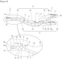
- the connector C includes a first body 71 fixed to the second surface 35 (rear surface) of the drum, a second body 73 to which the rotary shaft S is fixed, and a connecting portion 74 connecting the first body 71 with the second body 73.
- the connecting portion 74 is a means for forming a path through which water passes to a space between the first body 71 and the second body 73 as well as maintaining the state that the first body 71 is spaced apart from the second body 73.
- the first body 71 may include a first body hub 711 fixed to the second surface 35 and located in the center of rotation of the drum 3, and first body arms 713, 714 and 715 extended from the first body hub 711 toward the rim of the second surface 35.
- the connecting portion 74 may be provided in a shape of V pointed toward a direction far away from the rotary shaft S. That is, the connecting portion 74 may include a first connecting body 741 upwardly inclined from a left end of the first body first arm 713 toward the direction far away from the rotary shaft S, and a second connecting body 743 provided to be upwardly inclined from a right end of the first body first arm 713 toward the direction far away from the rotary shaft S.
- the water stored in the tub during rotation of the drum may move along the path 77 formed by the connecting portion 74. Therefore, the present invention may not only minimize particles and the like discharged from laundry remaining in the connector C but also wash the particles remaining in the connector C.
- the first body first arm 713 and the second body first arm 733 may be prevented from being bent toward the second surface 35, or may be prevented from being bent toward the direction far away from the second surface 35.
- the connecting point 745 provided in one connecting portion may be provided to be located in a space A2 formed by connecting (L2) the free end of the first connecting body with the free end of the second connecting body.
- the plurality of connecting portions 74 may be provided such that the connecting point 745 located outside a space A3 formed by connecting (L3) the free end of the first connecting body with the free end of the second connecting body and the connecting point 745 located in a space A4 formed by connecting (L4) the free end of the first connecting body with the free end of the second connecting body exist.
- the connecting portion is provided to include a first connecting portion, a second connecting portion and a third connecting portion, which are spaced apart from one another along the longitudinal direction of the first body first arm 713
- the connecting point where the first and second connecting bodies constituting the first connecting portion are connected with each other may be provided to be located in the space A4 formed by connecting the free end of the first connecting body and the free end of the second connecting body, which constitute the second connecting portion, with each other
- the connecting point where the first and second connecting bodies constituting the second connecting portion are connected with each other may be provided to be located outside the space A3 formed by connecting the free end of the first connecting body and the free end of the second connecting body, which constitute the third connecting portion, with each other.
- first body hub 711 and the second body hub 731 may be connected with each other through a hub connecting portion 747.
- One end of the hub connecting portion 747 may be provided with a board having one end fixed to the first body hub 711 and the other end fixed to the second body hub 731.
- the hub connecting portion 747 may be provided with a plurality of boards spaced apart from one another around the rotary shaft S at the same angle.
- the aforementioned connector C has been described based on that the first body arm is provided with only the first body first arm 713 and the second body arm is provided with only the second body first arm 733.
- the first body arm is provided with a first body first arm 713, a first body second arm 714, and a first body third arm 715
- the second body arm is provided with a second body first arm 733, a second body second arm 734, and a second body third arm 735.
- the first body arm may be provided with a first body first arm 713 extended from the first body hub 711 toward the rim of the second surface 35, a first body second arm 714 extended from the first body hub 711 toward the rim of the second surface 35, and a first body third arm 715 extended from the first body hub 711 toward the rim of the second surface 35.
- the respective arms 713, 714 and 715 are spaced apart from one another around the rotary shaft S at the same angle (120°).
- the second body arm may include a second body first arm 733 extended from the second body hub 731 along the same direction where the first body first arm 713 is extended from the first body hub 711, a second body second arm 734 extended from the second body hub 731 along the same direction where the first body second arm 714 is extended from the first body hub 711, and a second body third arm 735 extended from the second body hub 731 along the same direction where the first body third arm 715 is extended from the first body hub 711.
- first fastening body 751 which is provided with a first fastening groove 751a communicated with the first through hole 355 provided in the fastening rib 353.
- a second fastening body 753 connecting the free end of the first body second arm 714 and the free end of the second body second arm 734 is provided with a second fastening groove 753a communicated with the second through hole 356, and a third fastening body 755 connecting the free end of the first body third arm 715 and the free end of the second body third arm 735 is provided with a third fastening groove 755a communicated with the third through hole 357.
- the connecting portion 74 includes a first arm connecting portion connecting the first body first arm 713 with the second body first arm 733, a second arm connecting portion connecting the first body second arm 715 with the second body second arm 734, and a third arm connecting portion connecting the first body third arm 715 with the second body third arm 735.
- the structure of the first arm connecting portion, the structure of the second arm connecting portion, and the structure of the third arm connecting portion may be provided in the same manner as the structure of the connecting portion described with reference to FIGS. 4 to 6 .
- first arm connecting portion may be provided with first and second connecting bodies connecting the first body first arm 713 with the second body first arm 733
- the second arm connecting portion may be provided with first and second connecting bodies connecting the first body second arm 714 with the second body second arm 734
- the third arm connecting portion may be provided with first and second connecting bodies connecting the first body third arm 715 with the second body third arm 735.
- the present invention may be applied to a top-loading type laundry treating apparatus.
- the inlet 11 should be provided on the upper surface of the cabinet
- the tub inlet 23 should be provide on the upper surface of the cylindrical shaped tub body
- the first surface provided with the drum inlet should become the upper surface of the drum body 31
- the second surface to which the first body 71 of the connector is fixed should become the lower surface of the drum body 31.
- a laundry treating apparatus comprises a drum (3) rotatably provided inside the laundry treating apparatus for storing laundry; and a connector (C) connecting the drum (3) to a motor (41, 43) for transferring a rotation power to the drum (3)
- the connector (C) comprises a rotary shaft (S), a first body (71) having a first body hub (711) fixed to the drum (3), and at least one first body arm (713, 714, 715) extending from the first body hub (711) radially outwards; a second body (73) having a second body hub (731) fixed to the rotary shaft (S), and at least one second body arm (733, 734, 735) extending from the second body hub (731) radially outwards corresponding to the at least one first body arm (713, 714, 715); and at least one connecting portion (74) connecting the first body (71) with the second body (73) so that the first body (71) is spaced apart from the second body (73) forming paths (77) between the first body (7
- the rotary shaft may define an axis of rotation, i.e. the first and second body arms may extend radially outwards with respect to the axis of rotation.
- the first body hub is fixed to a rear surface of the drum, i.e. a surface opposite to a drum inlet for loading or unloading laundry into the drum.
- the laundry treating apparatus may further comprise a tub for storing water, the drum being rotatably provided inside the tub.
- the first body arm (713, 714, 715) and the second body arm (733, 734, 735) overlap each other.
- the first body arm (713, 714, 715) and the second body arm (733, 734, 735) may be connected to each other by the at least one connecting portion (74). That is, the first and second body arms may be facing each other with the connecting portion in between.
- the connecting portion (74) and/or the paths (77) may extend perpendicular to the axis of rotation defined by the rotary shaft (S). That is, the connecting portion (74) and/or the paths (77) may extend perpendicular to a radial direction. Preferably, the connecting portion (74) and/or the paths (77) extend along a width direction of the first and/or second body arm (713, 714, 715; 733, 734, 735), e.g. in a plane perpendicular to the axis of rotation.
- the at least one connecting portion (74) may respectively have a V shape or bent shape pointing towards or away from the rotary shaft (S).
- the connecting portion (74) may include a first connecting body (741) and a second connecting body (743) connected to each other at a connecting point (745) to form a V shape.
- the first and second connecting bodies may have a linear shape.
- connecting portions (74) closer to the axis of rotation have a V shape or bent shape pointing towards the rotary shaft (S).
- connecting portions (74) farther from the axis of rotation may have a V shape or bent shape pointing away from the rotary shaft (S).
- a connecting point (745) of a first connecting portion (74) may be located outside a space formed by connecting free ends of the first and second connecting bodies (741, 743) of a second connecting portion (74), the first connecting portion (74) being adjacent to and pointing towards the second connecting portion (74).
- a connecting point (745) of a third connecting portion (74) may be located inside a space formed by connecting free ends of the first and second connecting bodies (741, 743) of a fourth connecting portion (74), the third connecting portion (74) being adjacent to and pointing towards the fourth connecting portion (74).
- the first and second connecting portions (74) are arranged closer to the first or second body hub (711, 731) than the third connecting portion (74) along the first or second body arm (713, 714, 715; 733, 734, 735).
- the connecting portion (74) may include a first connecting body (741) and a second connecting body (743) connected to each other at a connecting point (745) to form a V shape.
- the rib (78) may extend from the connecting point (745) between the first connecting body (741) and the second connecting body (743), e.g. along a radial direction.
- the rib (78) may connect connecting points (745) of adjacent connecting portions (74).
- the rib (78) may extend along a radial direction.
- the rib (78) may be arranged between adjacent connecting portions (74) with a height increasing towards the first or second body hub (711, 731).
Landscapes
- Engineering & Computer Science (AREA)
- Textile Engineering (AREA)
- Main Body Construction Of Washing Machines And Laundry Dryers (AREA)
- Detail Structures Of Washing Machines And Dryers (AREA)
Applications Claiming Priority (4)
| Application Number | Priority Date | Filing Date | Title |
|---|---|---|---|
| KR1020180078893A KR102534478B1 (ko) | 2018-07-06 | 2018-07-06 | 의류처리장치 |
| EP21187545.5A EP3919667B1 (de) | 2018-07-06 | 2019-06-27 | Wäschebehandlungsvorrichtung |
| EP23191937.4A EP4249664B1 (de) | 2018-07-06 | 2019-06-27 | Wäschebehandlungsvorrichtung |
| EP19182819.3A EP3594401B1 (de) | 2018-07-06 | 2019-06-27 | Wäschebehandlungsvorrichtung |
Related Parent Applications (3)
| Application Number | Title | Priority Date | Filing Date |
|---|---|---|---|
| EP23191937.4A Division EP4249664B1 (de) | 2018-07-06 | 2019-06-27 | Wäschebehandlungsvorrichtung |
| EP19182819.3A Division EP3594401B1 (de) | 2018-07-06 | 2019-06-27 | Wäschebehandlungsvorrichtung |
| EP21187545.5A Division EP3919667B1 (de) | 2018-07-06 | 2019-06-27 | Wäschebehandlungsvorrichtung |
Publications (2)
| Publication Number | Publication Date |
|---|---|
| EP4534749A2 true EP4534749A2 (de) | 2025-04-09 |
| EP4534749A3 EP4534749A3 (de) | 2025-06-25 |
Family
ID=67105840
Family Applications (4)
| Application Number | Title | Priority Date | Filing Date |
|---|---|---|---|
| EP25158800.0A Pending EP4534749A3 (de) | 2018-07-06 | 2019-06-27 | Wäschebehandlungsvorrichtung |
| EP21187545.5A Active EP3919667B1 (de) | 2018-07-06 | 2019-06-27 | Wäschebehandlungsvorrichtung |
| EP23191937.4A Active EP4249664B1 (de) | 2018-07-06 | 2019-06-27 | Wäschebehandlungsvorrichtung |
| EP19182819.3A Active EP3594401B1 (de) | 2018-07-06 | 2019-06-27 | Wäschebehandlungsvorrichtung |
Family Applications After (3)
| Application Number | Title | Priority Date | Filing Date |
|---|---|---|---|
| EP21187545.5A Active EP3919667B1 (de) | 2018-07-06 | 2019-06-27 | Wäschebehandlungsvorrichtung |
| EP23191937.4A Active EP4249664B1 (de) | 2018-07-06 | 2019-06-27 | Wäschebehandlungsvorrichtung |
| EP19182819.3A Active EP3594401B1 (de) | 2018-07-06 | 2019-06-27 | Wäschebehandlungsvorrichtung |
Country Status (5)
| Country | Link |
|---|---|
| US (5) | US11365500B2 (de) |
| EP (4) | EP4534749A3 (de) |
| KR (5) | KR102534478B1 (de) |
| CN (2) | CN110685118B (de) |
| AU (1) | AU2019204701B2 (de) |
Families Citing this family (6)
| Publication number | Priority date | Publication date | Assignee | Title |
|---|---|---|---|---|
| US10357567B1 (en) | 2018-01-12 | 2019-07-23 | Dusa Pharmaceuticals, Inc. | Methods for photodynamic therapy |
| US11846057B2 (en) * | 2019-12-17 | 2023-12-19 | Wade Chapman | Stabilizer for a rotatable drum |
| KR20220109907A (ko) * | 2021-01-29 | 2022-08-05 | 엘지전자 주식회사 | 의류처리장치 |
| KR20220122240A (ko) * | 2021-02-26 | 2022-09-02 | 엘지전자 주식회사 | 의류처리장치 |
| KR102776910B1 (ko) * | 2021-04-21 | 2025-03-10 | 엘지전자 주식회사 | 의류처리장치 |
| US20250034784A1 (en) * | 2023-07-26 | 2025-01-30 | Whirlpool Corporation | Laundry crosspiece |
Citations (1)
| Publication number | Priority date | Publication date | Assignee | Title |
|---|---|---|---|---|
| KR20180078893A (ko) | 2016-12-30 | 2018-07-10 | 롯데첨단소재(주) | 고무 공중합체 및 이를 포함하는 열가소성 수지 조성물 |
Family Cites Families (25)
| Publication number | Priority date | Publication date | Assignee | Title |
|---|---|---|---|---|
| KR20010003902A (ko) | 1999-06-26 | 2001-01-15 | 윤종용 | 드럼세탁기의 베어링 냉각장치 |
| KR100505233B1 (ko) | 2002-12-10 | 2005-08-03 | 엘지전자 주식회사 | 드럼 세탁기 |
| US20050252252A1 (en) * | 2004-05-15 | 2005-11-17 | Lg Electronics Inc. | Drum for washing machine |
| KR100729455B1 (ko) * | 2005-10-19 | 2007-06-15 | 원창산업(주) | 플랜지 조립체를 가진 드럼 세탁기 |
| KR101191194B1 (ko) * | 2006-05-01 | 2012-10-15 | 엘지전자 주식회사 | 드럼세탁기의 스파이더 구조 |
| KR100805231B1 (ko) | 2006-11-24 | 2008-02-21 | 삼성전자주식회사 | 드럼세탁기 |
| WO2009003875A1 (en) * | 2007-06-29 | 2009-01-08 | Basf Se | Basket assembly for a washing machine |
| KR101222861B1 (ko) * | 2007-10-15 | 2013-01-16 | 삼성전자주식회사 | 샤프트플랜지 및 이를 갖는 세탁기 |
| KR20100034898A (ko) * | 2008-09-25 | 2010-04-02 | 삼성전자주식회사 | 세탁기 |
| KR101068830B1 (ko) | 2009-03-31 | 2011-09-29 | 양덕수 | 세탁기용 플랜지 샤프트 |
| KR101692727B1 (ko) | 2009-05-28 | 2017-01-04 | 엘지전자 주식회사 | 세탁장치 |
| KR20130077997A (ko) * | 2011-12-30 | 2013-07-10 | 동부대우전자 주식회사 | 세탁기용 펄세이터 |
| US9441697B2 (en) * | 2012-06-07 | 2016-09-13 | Samsung Electronics Co., Ltd. | Balancing module and washing machine having the same |
| WO2013183929A1 (en) | 2012-06-07 | 2013-12-12 | Samsung Electronics Co., Ltd. | Balancer, balancer housing, washing machine having the same and control method thereof |
| PL2671995T3 (pl) * | 2012-06-07 | 2015-07-31 | Samsung Electronics Co Ltd | Wyważarka, obudowa wyważarki, pralka, która jest w nie wyposażona i sposób jej sterowania |
| KR102116536B1 (ko) * | 2012-06-07 | 2020-05-29 | 삼성전자주식회사 | 밸런싱 모듈 및 이를 구비하는 세탁기 |
| JP6397254B2 (ja) * | 2014-08-04 | 2018-09-26 | アクア株式会社 | ドラム式洗濯機 |
| KR102329421B1 (ko) * | 2015-04-01 | 2021-11-22 | 엘지전자 주식회사 | 의류처리장치 |
| KR102436701B1 (ko) * | 2015-10-01 | 2022-08-25 | 엘지전자 주식회사 | 세탁물 처리장치 |
| KR20180023288A (ko) * | 2016-08-25 | 2018-03-07 | 엘지전자 주식회사 | 의류처리장치 |
| CN106498660B (zh) * | 2016-09-21 | 2019-01-01 | Tcl家用电器(合肥)有限公司 | 内筒组件和洗衣机 |
| CN106498680A (zh) | 2016-10-28 | 2017-03-15 | 衡阳智源农业科技有限公司 | 一种内衣物干燥消毒装置 |
| CN106498860B (zh) | 2016-11-28 | 2018-09-21 | 柳州欧维姆工程有限公司 | 一种用于拱桥旧吊杆拆除的整束顶拔钢丝及清孔的方法 |
| CN106681795B (zh) | 2016-12-09 | 2020-04-28 | 北京航空航天大学 | 节点局部拓扑和可利用资源容量的虚拟网络映射方法 |
| KR102426575B1 (ko) * | 2017-08-18 | 2022-07-28 | 삼성전자주식회사 | 세탁기 |
-
2018
- 2018-07-06 KR KR1020180078893A patent/KR102534478B1/ko active Active
-
2019
- 2019-06-27 EP EP25158800.0A patent/EP4534749A3/de active Pending
- 2019-06-27 EP EP21187545.5A patent/EP3919667B1/de active Active
- 2019-06-27 EP EP23191937.4A patent/EP4249664B1/de active Active
- 2019-06-27 EP EP19182819.3A patent/EP3594401B1/de active Active
- 2019-07-02 AU AU2019204701A patent/AU2019204701B2/en active Active
- 2019-07-03 US US16/502,873 patent/US11365500B2/en active Active
- 2019-07-05 CN CN201910602351.2A patent/CN110685118B/zh active Active
- 2019-07-05 CN CN202111477136.8A patent/CN114134681B/zh active Active
-
2022
- 2022-06-06 US US17/833,579 patent/US11761135B2/en active Active
- 2022-06-06 US US17/833,561 patent/US11891743B2/en active Active
- 2022-06-06 US US17/833,554 patent/US11913157B2/en active Active
- 2022-06-06 US US17/833,548 patent/US11879199B2/en active Active
-
2023
- 2023-05-15 KR KR1020230062635A patent/KR102614503B1/ko active Active
- 2023-11-24 KR KR1020230165525A patent/KR102647036B1/ko active Active
-
2024
- 2024-02-22 KR KR1020240025587A patent/KR102674541B1/ko active Active
- 2024-05-17 KR KR1020240064373A patent/KR102805592B1/ko active Active
Patent Citations (1)
| Publication number | Priority date | Publication date | Assignee | Title |
|---|---|---|---|---|
| KR20180078893A (ko) | 2016-12-30 | 2018-07-10 | 롯데첨단소재(주) | 고무 공중합체 및 이를 포함하는 열가소성 수지 조성물 |
Also Published As
Similar Documents
| Publication | Publication Date | Title |
|---|---|---|
| EP4534749A2 (de) | Wäschebehandlungsvorrichtung | |
| RU2326193C2 (ru) | Узел барабана для стиральной машины (варианты) | |
| KR102091603B1 (ko) | 의류처리장치 | |
| KR20130034911A (ko) | 리프터와 이를 가지는 세탁기 | |
| KR20100018239A (ko) | 볼밸런서 및 이를 구비한 세탁장치 | |
| CN107923106B (zh) | 洗衣机 | |
| KR20100018241A (ko) | 볼 밸런서 및 이를 구비한 세탁장치 | |
| EP1840256A1 (de) | Waschtrommel und Waschmaschine oder Trockner damit | |
| KR102557928B1 (ko) | 리프터 및 이를 가지는 세탁기 | |
| EP4036301A1 (de) | Vorrichtung zur behandlung von wäsche | |
| US11427949B2 (en) | Washing machine | |
| EP3504371B1 (de) | Waschmaschine |
Legal Events
| Date | Code | Title | Description |
|---|---|---|---|
| PUAI | Public reference made under article 153(3) epc to a published international application that has entered the european phase |
Free format text: ORIGINAL CODE: 0009012 |
|
| STAA | Information on the status of an ep patent application or granted ep patent |
Free format text: STATUS: REQUEST FOR EXAMINATION WAS MADE |
|
| 17P | Request for examination filed |
Effective date: 20250219 |
|
| AC | Divisional application: reference to earlier application |
Ref document number: 3594401 Country of ref document: EP Kind code of ref document: P Ref document number: 3919667 Country of ref document: EP Kind code of ref document: P Ref document number: 4249664 Country of ref document: EP Kind code of ref document: P |
|
| AK | Designated contracting states |
Kind code of ref document: A2 Designated state(s): AL AT BE BG CH CY CZ DE DK EE ES FI FR GB GR HR HU IE IS IT LI LT LU LV MC MK MT NL NO PL PT RO RS SE SI SK SM TR |
|
| REG | Reference to a national code |
Ref country code: DE Ref legal event code: R079 Free format text: PREVIOUS MAIN CLASS: D06F0037300000 Ipc: D06F0037040000 |
|
| PUAL | Search report despatched |
Free format text: ORIGINAL CODE: 0009013 |
|
| AK | Designated contracting states |
Kind code of ref document: A3 Designated state(s): AL AT BE BG CH CY CZ DE DK EE ES FI FR GB GR HR HU IE IS IT LI LT LU LV MC MK MT NL NO PL PT RO RS SE SI SK SM TR |
|
| RIC1 | Information provided on ipc code assigned before grant |
Ipc: D06F 37/30 20200101ALI20250521BHEP Ipc: D06F 37/04 20060101AFI20250521BHEP |
|
| GRAP | Despatch of communication of intention to grant a patent |
Free format text: ORIGINAL CODE: EPIDOSNIGR1 |
|
| STAA | Information on the status of an ep patent application or granted ep patent |
Free format text: STATUS: GRANT OF PATENT IS INTENDED |
|
| INTG | Intention to grant announced |
Effective date: 20260325 |