EP4534754A1 - Appareil de filtration et appareil de traitement de vêtements le comprenant - Google Patents
Appareil de filtration et appareil de traitement de vêtements le comprenant Download PDFInfo
- Publication number
- EP4534754A1 EP4534754A1 EP23852688.3A EP23852688A EP4534754A1 EP 4534754 A1 EP4534754 A1 EP 4534754A1 EP 23852688 A EP23852688 A EP 23852688A EP 4534754 A1 EP4534754 A1 EP 4534754A1
- Authority
- EP
- European Patent Office
- Prior art keywords
- filter
- sensor
- case
- water
- washing machine
- Prior art date
- Legal status (The legal status is an assumption and is not a legal conclusion. Google has not performed a legal analysis and makes no representation as to the accuracy of the status listed.)
- Pending
Links
Images


Classifications
-
- B—PERFORMING OPERATIONS; TRANSPORTING
- B01—PHYSICAL OR CHEMICAL PROCESSES OR APPARATUS IN GENERAL
- B01D—SEPARATION
- B01D29/00—Filters with filtering elements stationary during filtration, e.g. pressure or suction filters, not covered by groups B01D24/00 - B01D27/00; Filtering elements therefor
- B01D29/11—Filters with filtering elements stationary during filtration, e.g. pressure or suction filters, not covered by groups B01D24/00 - B01D27/00; Filtering elements therefor with bag, cage, hose, tube, sleeve or like filtering elements
- B01D29/13—Supported filter elements
- B01D29/23—Supported filter elements arranged for outward flow filtration
-
- B—PERFORMING OPERATIONS; TRANSPORTING
- B01—PHYSICAL OR CHEMICAL PROCESSES OR APPARATUS IN GENERAL
- B01D—SEPARATION
- B01D29/00—Filters with filtering elements stationary during filtration, e.g. pressure or suction filters, not covered by groups B01D24/00 - B01D27/00; Filtering elements therefor
- B01D29/60—Filters with filtering elements stationary during filtration, e.g. pressure or suction filters, not covered by groups B01D24/00 - B01D27/00; Filtering elements therefor integrally combined with devices for controlling the filtration
- B01D29/605—Filters with filtering elements stationary during filtration, e.g. pressure or suction filters, not covered by groups B01D24/00 - B01D27/00; Filtering elements therefor integrally combined with devices for controlling the filtration by level measuring
-
- B—PERFORMING OPERATIONS; TRANSPORTING
- B01—PHYSICAL OR CHEMICAL PROCESSES OR APPARATUS IN GENERAL
- B01D—SEPARATION
- B01D29/00—Filters with filtering elements stationary during filtration, e.g. pressure or suction filters, not covered by groups B01D24/00 - B01D27/00; Filtering elements therefor
- B01D29/62—Regenerating the filter material in the filter
- B01D29/64—Regenerating the filter material in the filter by scrapers, brushes, nozzles, or the like, acting on the cake side of the filtering element
- B01D29/6469—Regenerating the filter material in the filter by scrapers, brushes, nozzles, or the like, acting on the cake side of the filtering element scrapers
- B01D29/6476—Regenerating the filter material in the filter by scrapers, brushes, nozzles, or the like, acting on the cake side of the filtering element scrapers with a rotary movement with respect to the filtering element
-
- B—PERFORMING OPERATIONS; TRANSPORTING
- B01—PHYSICAL OR CHEMICAL PROCESSES OR APPARATUS IN GENERAL
- B01D—SEPARATION
- B01D35/00—Filtering devices having features not specifically covered by groups B01D24/00 - B01D33/00, or for applications not specifically covered by groups B01D24/00 - B01D33/00; Auxiliary devices for filtration; Filter housing constructions
- B01D35/02—Filters adapted for location in special places, e.g. pipe-lines, pumps, stop-cocks
-
- B—PERFORMING OPERATIONS; TRANSPORTING
- B01—PHYSICAL OR CHEMICAL PROCESSES OR APPARATUS IN GENERAL
- B01D—SEPARATION
- B01D35/00—Filtering devices having features not specifically covered by groups B01D24/00 - B01D33/00, or for applications not specifically covered by groups B01D24/00 - B01D33/00; Auxiliary devices for filtration; Filter housing constructions
- B01D35/14—Safety devices specially adapted for filtration; Devices for indicating clogging
- B01D35/143—Filter condition indicators
-
- B—PERFORMING OPERATIONS; TRANSPORTING
- B01—PHYSICAL OR CHEMICAL PROCESSES OR APPARATUS IN GENERAL
- B01D—SEPARATION
- B01D35/00—Filtering devices having features not specifically covered by groups B01D24/00 - B01D33/00, or for applications not specifically covered by groups B01D24/00 - B01D33/00; Auxiliary devices for filtration; Filter housing constructions
- B01D35/16—Cleaning-out devices, e.g. for removing the cake from the filter casing or for evacuating the last remnants of liquid
-
- D—TEXTILES; PAPER
- D06—TREATMENT OF TEXTILES OR THE LIKE; LAUNDERING; FLEXIBLE MATERIALS NOT OTHERWISE PROVIDED FOR
- D06F—LAUNDERING, DRYING, IRONING, PRESSING OR FOLDING TEXTILE ARTICLES
- D06F34/00—Details of control systems for washing machines, washer-dryers or laundry dryers
- D06F34/14—Arrangements for detecting or measuring specific parameters
- D06F34/20—Parameters relating to constructional components, e.g. door sensors
-
- D—TEXTILES; PAPER
- D06—TREATMENT OF TEXTILES OR THE LIKE; LAUNDERING; FLEXIBLE MATERIALS NOT OTHERWISE PROVIDED FOR
- D06F—LAUNDERING, DRYING, IRONING, PRESSING OR FOLDING TEXTILE ARTICLES
- D06F39/00—Details of washing machines not specific to a single type of machines covered by groups D06F9/00 - D06F27/00
- D06F39/10—Filtering arrangements
-
- B—PERFORMING OPERATIONS; TRANSPORTING
- B01—PHYSICAL OR CHEMICAL PROCESSES OR APPARATUS IN GENERAL
- B01D—SEPARATION
- B01D2201/00—Details relating to filtering apparatus
- B01D2201/08—Regeneration of the filter
-
- B—PERFORMING OPERATIONS; TRANSPORTING
- B01—PHYSICAL OR CHEMICAL PROCESSES OR APPARATUS IN GENERAL
- B01D—SEPARATION
- B01D2201/00—Details relating to filtering apparatus
- B01D2201/28—Position of the filtering element
- B01D2201/282—Filtering elements with a horizontal rotation or symmetry axis
Definitions
- the washing machine includes a drain device configured to discharge water stored in the tub to the outside of the washing machine while the washing operation, the rinsing operation, and/or the dehydrating operation is performed.
- the drain device may be configured to return water discharged from the tub to the tub while the washing operation and/or the rinsing operation is performed.
- Embodiments of the disclosure may provide a filter apparatus being easily manageable and a clothes treating apparatus having the filter apparatus.
- a clothes treating apparatus may include: a washing machine including a washing machine housing, a tub provided inside the washing machine housing, and a drain device configured to discharge water stored in the tub to outside of the washing machine housing; and a filter apparatus positioned outside the washing machine housing and being connectable to the drain device of the washing machine.
- the filter apparatus may include a filter case, a filter being detachably installable in the filter case, a filter cleaning device including a cleaning driver configured to clean the filter, a sensor configured to detect water entered the filter apparatus, and a controller configured to control an operation of the filter cleaning device based on information obtained through the sensor.
- each of such phrases as “A or B,” “at least one of A and B,” “at least one of A or B,” “A, B, or C,” “at least one of A, B, and C,” and “at least one of A, B, or C,” may include any one of, or all possible combinations of the items enumerated together in a corresponding one of the phrases.
- the washing machine may include a top-loading washing machine, wherein an inlet through which laundry is put into or taken out of the top-loading washing machine is provided upward, or a front-loading washing machine, wherein an inlet through which laundry is put into or taken out of the front-loading washing machine is provided forward.
- the washing machine according to various embodiments of the disclosure may include another loading type of washing machine, other than the top-loading washing machine and the front-loading washing machine.
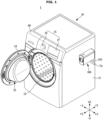
- the clothes treating apparatus 1 which in this embodiment is the washing machine, may include a washing machine housing 11 for accommodating various components therein.
- the washing machine housing 11 may form an appearance of the washing machine 10.
- the washing machine housing 11 may be in a shape of a box of which a portion opens.
- the washing machine housing 11 may include a housing opening 12 allowing an access to inside of a drum 30.
- the housing opening 12 may open substantially toward a front direction.
- the washing machine 10 may include a door 13 for opening or closing the housing opening 12 provided in the washing machine housing 11.
- the door 13 may be rotatably mounted on the washing machine housing 11 by a hinge 14. At least one portion of the door 13 may be transparent or translucent to show the inside of the washing machine housing 11.
- the washing machine 10 may include a tub 20 provided inside the washing machine housing 11 to store water.
- the tub 20 may be positioned inside the washing machine housing 11.
- the tub 20 may include a tub opening 22 corresponding to the housing opening 12.
- the tub opening 22 may open substantially toward the front direction.
- the tub 20 may be supported inside the washing machine housing 11.
- the tub 20 may have a substantially cylindrical shape of which one side opens.
- the washing machine 10 may include the drum 30 accommodating laundry.
- the drum 30 may be rotatably provided inside the tub 20.
- the drum 30 may perform washing, rinsing, and/or dehydrating while rotating inside the tub 20.
- the drum 30 may include a through hole 34 that connects an inside space of the drum 30 to an inside space of the tub 20.
- the drum 30 may have a substantially cylindrical shape of which one side opens.
- On an inner circumferential surface of the drum 30, at least one lifter 35 may be installed to raise and drop laundry according to a rotation of the drum 30.
- the washing machine 10 may include a washing machine driver 40 configured to rotate the drum 30.
- the washing machine driver 40 may include a driving motor 41, and a rotating shaft 42 for transferring a driving force generated in the driving motor 41 to the drum 30.
- the rotating shaft 42 may penetrate the tub 20 and be connected to the drum 30.
- Washing machines may be classified into a direct driving type in which the rotating shaft 41 is connected directly to the driving motor 41 to rotate the drum 30, and an indirect driving type in which a pulley 43 is connected between the driving motor 41 and the rotating shaft 42 to drive the drum 30.
- One end of the rotating shaft 42 may be connected to the drum 30, and another end may be connected to the pulley 43 to receive power from the driving motor 41.
- a motor pulley 41a may be formed at the rotating shaft 42 of the driving motor 41.
- a driving belt 44 may be provided between the motor pulley 41a and the pulley 43 such that the rotating shaft 42 is driven by the driving belt 44.
- the washing machine driver 40 may rotate the drum 30 forward or backward to perform a washing operation, a rinsing operation, and/or a dehydrating operation or a drying operation.
- the washing machine 10 may include a water supply device 50.
- the water supply device 50 may supply water to the tub 20.
- the water supply device 50 may be positioned above the tub 20.
- the water supply device 50 may include a water supply tube 51, and a water supply valve 56 provided in the water supply tube 51.
- the water supply tube 51 may be connected to an external water supply source.
- the water supply tube 51 may extend to a detergent supply device 60 and/or the tub 20 from the external water supply source. Water may be supplied to the tub 20 via the detergent supply device 60. Water may be supplied to the tub 20 not via the detergent supply device 60.
- the washing machine 10 may include the detergent supply device 60 configured to supply a detergent to the tub 20.
- the detergent supply device 60 may supply a detergent to the inside of the tub 20 during a water supply process. Water supplied through the water supply tube 51 may be mixed with a detergent via the detergent supply device 60. The water mixed with the detergent may be supplied to the inside of the tub 20.
- the detergent may include a conditioner for dryer, a deodorant, a sterilizer, or an air freshener, as well as a washing detergent.
- the detergent supply device 60 may be connected to the tub 20 through a connecting tube 61.
- the washing machine 10 may provide a user interface 15 for interactions with a user.
- the clothes treating apparatus 1 may include a filter apparatus 100 that is connectable to the drain device 70 of the washing machine 10.
- the filter apparatus 100 may be positioned outside the washing machine 10.
- the filter apparatus 100 may filter foreign materials from water discharged from the washing machine 10.
- the filter apparatus 100 may filter foreign materials having smaller sizes than those of foreign materials that are capable of being filtered in the washing machine 10.
- the filter apparatus 100 may filter foreign materials having smaller sizes than those of foreign materials that are capable of being filtered in the drain device 70 of the washing machine 10.
- FIG. 3 is a control block diagram of a washing machine according to an embodiment of the disclosure.
- the user interface 15 may include at least one input interface 16.
- the user interface 15 may include at least one output interface 17.
- the at least one input interface 16 may convert sensory information received from a user into an electrical signal.
- the at least one output interface 17 may generate sensory information and transfer various data related to an operation of the washing machine 10 to a user.
- the at least one output interface 17 may transfer information related to a washing course and an operation time of the washing machine 10 or a washing setting/rinsing setting/dehydrating setting to a user. Information related to an operation of the washing machine 10 may be output through a screen, an indicator, a voice, etc.
- the at least one output interface 17 may include, for example, a Liquid Crystal Display (LCD) panel, a Light Emitting Diode (LED) panel, a speaker, etc.
- LCD Liquid Crystal Display
- LED Light Emitting Diode
- the water supply device 50 may include the water supply valve 56 for opening or closing the water supply tube 51 extending from the external water supply source to the detergent supply device 60 and/or the tub 20.
- the water supply valve 56 may be opened or closed based on a control signal from the controller 90.
- the drain device 70 may include the drain pump 73 for discharging water stored in the tub 20 to the outside of the washing machine housing 11.
- the drain pump 73 may operate based on a control signal from the controller 90.
- the washing machine 10 may include the communication module 96 for communicating with an external device wiredly or wirelessly.
- the communication module 96 may include at least one of a short-range wireless communication module or a long-distance wireless communication module.
- the communication module 96 may transmit data to an external device (for example, a server, a user device, a home appliance, and/or the filter apparatus 100), or receive data from an external device.
- the communication module 96 may establish communication with a server and/or a user device and/or a home appliance and transmit/receive various data to/from the server and/or the user device and/or the home appliance.
- the communication module 96 may support establishment of a direct (for example, wired) communication channel or a wireless communication channel with an external device, and communications through an established communication channel.
- the communication module 96 may include a wireless communication module (for example, a cellular communication module, a short-range wireless communication module, or a global navigation satellite system (GNSS) communication module) or a wired communication module (for example, a local area network (LAN) communication module or a power line communication module).
- GNSS global navigation satellite system
- a corresponding communication module among the communication modules may communicate with an external electronic device through a first network (for example, a short-range wireless communication network, such as Bluetooth, WiFi Direct, or Infrared data association (IrDA)) or a second network (for example, a long-distance wireless communication network, such as a legacy cellular network, a 5th Generation (5G) network, a next-generation communication network, the Internet, or a computer network (for example, a LAN or a wide area network (WAN)).
- the various kinds of communication modules may be integrated into a single component (for example, a single chip) or implemented with a plurality of separate components (for example, a plurality of chips).
- the communication module may communicate with an external device, such as a server, a user device, another home appliance, etc., through a surrounding Access Point (AP).
- the AP may connect a LAN to which the washing machine 10 or a user device is connected to a WAN to which a server is connected.
- the washing machine 10 or the user device may be connected to the server through the WAN.
- the controller 90 may control various components (for example, the driver 40 or the water supply device 50) of the washing machine 10.
- the controller 90 may control various components of the washing machine 10 to perform at least one operation including water supply, washing, rinsing, and/or dehydrating according to a user input.
- the controller 90 may control the driving motor 41 to adjust a rotation speed of the drum 30, or the water supply valve 56 of the water supply device 50 to supply water to the tub 20.
- the controller 90 may include hardware such as a central processing unit (CPU) or a memory, and software such as a control program.
- the controller 90 may include at least one memory 92 that stores data in the form of an algorithm or program for controlling operations of components in the washing machine 10, and at least one processor 91 that performs the above-described operations by using the data stored in the at least one memory 92.
- the memory 92 and the processor 91 may be implemented with separate chips.
- the processor 91 may include one, two, or more processor chips or one, two, or more processing cores.
- the memory 92 may include one, two, or more memory chips or one, two, or more memory blocks. Also, the memory 92 and the processor 91 may be implemented with a single chip.
- FIG. 4 shows a clothes treating apparatus, which in this embodiment is a washing machine, according to an embodiment of the disclosure.
- FIG. 5 shows a cross section of the washing machine shown in FIG. 4 .
- a clothes treating apparatus 1a which in this embodiment is a washing machine 10a, may include a washing machine housing 11a for accommodating various components therein.
- the washing machine housing 11a may form an appearance of the washing machine 10a.
- the washing machine housing 11a may be in a shape of a box of which a portion opens.
- the washing machine housing 11a may include a housing opening 12a allowing an access to inside of a drum 30a.
- the housing opening 12a may open substantially toward the front direction.
- the washing machine 10a may include a door 13a for opening or closing the housing opening 12a provided in the washing machine housing 11a.
- the door 13a may be rotatably mounted on the washing machine housing 11a by a hinge. At least one portion of the door 13a may be transparent or translucent to show the inside of the washing machine housing 11a.
- the washing machine 10a may include a tub 20a provided inside the washing machine housing 11a to store water.
- the tub 20a may be positioned inside the washing machine housing 11a.
- the tub 20a may include a tub opening 22a corresponding to the housing opening 12a.
- the tub opening 22a may open substantially upward.
- the tub 20a may be supported inside the washing machine housing 11a.
- the tub 20a may have a substantially cylindrical shape of which one side opens.
- the tub 20a may be elastically supported from the washing machine housing 11a by a damper 80a.
- the damper 80a may connect the tub 20a to the washing machine housing 11a. While vibrations generated according to a rotation of the drum 30a are transferred to the tub 20a and/or the washing machine housing 11a, the damper 80a may absorb vibration energy between the tub 20a and the washing machine housing 11a to attenuate the vibrations.
- the washing machine 10a may include the drum 30a accommodating laundry.
- the drum 30a may be rotatably provided inside the tub 20a.
- the drum 30a may perform washing, rinsing, and/or dehydrating while rotating inside the tub 20a.
- the drum 30a may include a through hole 34a connecting an inside space of the drum 30a to an inside space of the tub 20a.
- the drum 30a may have a substantially cylindrical shape of which one side opens.
- a balancing unit 36a for releasing load imbalance caused by laundry may be installed on an upper portion of the drum 30a.
- the balancing unit 36a may include a housing having a circular channel, and a mass body of a ball or fluid being movable inside the channel, and while the ball or fluid moves according to a rotation of the drum 30a, the load imbalance of the drum 30a may be released.
- a pulsator 37a may be rotatably provided on a lower portion of the drum 30a to generate water streams for washing. Laundry may be washed by water streams for washing generated by the pulsator 37a.
- the drum 30a may include a drum opening 32a corresponding to the housing opening 12a and the tub opening 22a. Laundry may be put into or taken out of the drum 30a through the housing opening 12a, the tub opening 22a, and the drum opening 32a.
- the washing machine 10a may include a washing machine driver 40a configured to rotate the drum 30a and the pulsator 37a.
- the washing machine driver 40a may include a driving motor 41a, and a shafting for transferring a driving force generated in the driving motor 41 to the drum 30a and the pulsator 37a.
- the driving motor 41a may include a stator 48a fixed, and a rotor 49a rotating by electromagnetically interworking with the stator 48a.
- the shafting may include a dehydrating shaft 47a for transferring a driving force of the driving motor 41a to the drum 30a, a washing shaft 46a for transferring a driving force of the driving motor 41a to the pulsator 37a, and a clutch device 45a connecting/disconnecting the driving motor 41a to/from the dehydrating shaft 47a.
- the dehydrating shaft 47a may have a cavity, and the washing shaft 46a may be provided in the cavity of the dehydrating shaft 47a.
- the washing shaft 46a may be connected to the rotor 49a of the driving motor 46a, and the dehydrating shaft 47a may be connected to or disconnected from the rotor 49a of the driving motor 41a by the clutch device 45a.
- the washing machine 10a may include a water supply device 50a.
- the water supply device 50a may supply water to the tub 20a.
- the water supply device 50a may be positioned above the tub 20a.
- the water supply device 50a may include a water supply tube, and a water supply valve provided in the water supply tube.
- the water supply tube may be connected to an external water supply source.
- the water supply tube may extend from the external water supply source to a detergent supply device 60a and/or the tub 20a. Water may be supplied to the tub 20a via the detergent supply device 60a. Water may be supplied to the tub 20a not via the detergent supply device 60a.
- the washing machine 10a may include the detergent supply device 60a configured to supply a detergent to the tub 20a.
- the detergent supply device 60a may supply a detergent to the inside of the tub 20a during a water supply process. Water supplied through the water supply tube may be mixed with a detergent via the detergent supply device 60a. The water mixed with the detergent may be supplied to the inside of the tub 20a.
- the detergent may include a conditioner for dryer, a deodorant, a sterilizer, or an air freshener, as well as a washing detergent.
- the washing machine 10a may include at least one user interface 15a.
- the user interface 15a may include at least one input interface 16a and/or at least one output interface 17a.
- the at least one input interface 16a may include a power button, an operation button, a course selection dial (or a course selection button), and a washing/rinsing/dehydrating setting button.
- the at least one input interface 16a may include, for example, a tact switch, a push switch, a slide switch, a toggle switch, a micro switch, a touch switch, a touch pad, a touch screen, a jog dial, and/or a microphone, etc.
- the clothes treating apparatus 1a may include the same filter apparatus 100 as the filter apparatus 100 shown in FIGS. 1 and 2 .
- the filter apparatus 100 may be connected to a front-loading washing machine or a top-loading washing machine.
- the filter apparatus 100 may be connectable to the drain device 70a of the washing machine 10a.
- the filter apparatus 100 may be positioned outside the washing machine 10a.
- the filter apparatus 100 may filter foreign materials from water discharged from the washing machine 10a.
- the filter apparatus 100 may filter foreign materials having smaller sizes than those of foreign materials that are filterable in the washing machine 10a.
- the filter apparatus 100 may filter foreign materials having smaller sizes than those of foreign materials that are filterable in the drain device 70a of the washing machine 10a.
- the housing body 102 may include a housing inlet 102a through which water enters the filter apparatus 100, and a housing outlet 102b through which water stored in the filter apparatus 100 is discharged from the filter apparatus 100.
- the housing inlet 102a and/or the housing outlet 102b may be positioned in a lower portion of the housing body 102.
- the housing bracket 104 may cover the open rear side of the housing body 102.
- the housing bracket 104 may be detachably coupled to the housing body 102 and/or the housing cover 103.
- the housing bracket 104 may include a cable opening 104a to pass a power cable 109 through.
- the housing bracket 104 may include a connector installation portion 104b to which a connector 108 for communicating with an external device including the washing machine 10, etc., is connectable.
- the filter apparatus 100 may include a filter case 110 positioned inside the filter housing 101.
- the filter case 110 may form a flow path through which water entered into the filter apparatus 100 passes.
- the filter case 110 may accommodate the filter 120.
- the filter case 110 may include a case body 111 and a case cover 112.
- the case body 111 may include the case outlet 111b for discharging water that has entered the filter case 110 from the filter case 110.
- the case outlet 111b may be positioned in a lower portion of the case body 111.
- the case outlet 111b may be adjacent to the case opening 111a.
- the case outlet 111b may be close to another end of the filter 120, being opposite to one end of the filter 120 at which a filter opening 120a is positioned.
- the case outlet 111b may be closer to a second filter portion 122 of the filter 120 than a first filter portion 121 of the filter 120.
- the case cover 112 may include the case inlet 112a through which water enters the filter case 110.
- the case inlet 112a may be connected to the housing inlet 102a.
- the filter apparatus 100 may include an inlet guide 106 for connecting the case inlet 112a to the housing inlet 102a.
- the case inlet 102a may be integrated into the inlet guide 106.
- the case inlet 112a, the inlet guide 106, and the housing inlet 102a may be integrated into one body.
- the case cover 112 may include a motor installation portion 112b for installing a filter cleaning device 130.
- the motor installation portion 112b may be positioned above the case inlet 112a.
- a cleaning motor 136 of the filter cleaning device 130 may be installed at the motor installation portion 112b.
- the filter apparatus 100 may include the filter 120 that is detachably coupled to the filter case 110.
- the filter 120 may filter foreign materials having fine sizes.
- the filter 120 may filter microplastics having sizes of about 5 mm or less.
- the filter 120 may include a mesh filter.
- the filter 120 may extend substantially between the case inlet 112a and the case outlet 111b.
- the filter 120 may include the filter opening 120a that opens toward the case inlet 112a upon installation in the filter case 110. Water entered into the filter case 110 through the case inlet 112a may move to the inside of the filter 120 through the filter opening 120a.
- the filter apparatus 100 may include a handle 129 of which at least one portion is exposed to outside of the filter housing 101 upon installation of the filter 120 in the filter case 110.
- the handle 129 may be detachably coupled to the filter 120. Because the handle 129 is detachably coupled to the filter 120, the filter 120 may be easily maintained and repaired.
- the handle 129 may be coupled to the cover opening 103a and/or the case opening 111a by rotating.
- the filter apparatus 100 may include the filter cleaning device 130 for cleaning the filter 120.
- the filter cleaning device 130 may be installed in the filter case 110.
- the filter cleaning device 130 may include a cleaning member 131 for cleaning a surface of the filter 120 through which foreign materials are filtered.
- the filter cleaning device 130 may include a cleaning driver 135 for driving the cleaning member 131.
- the cleaning member 131 While the cleaning member 131 is driven by the cleaning driver 135, the cleaning member 131 may transfer foreign materials filtered in a portion of the filter 120 being close to the case inlet 112a to another portion of the filter 120 being close to the case outlet 111b.
- the cleaning member 131 may transfer foreign materials filtered in the first filter portion 121 to the second filter portion 122.
- the cleaning member 131 may be rotatably provided inside the filter 120.
- the cleaning member 131 may include a flexible material. The cleaning member 131 may clean foreign materials filtered in the filter 120 while rotating in a state of being in contact with the filter 120.
- the cleaning member 131 While the cleaning member 131 is driven in the state of being in contact with the filter 120, the cleaning member 131 may remove foreign materials attached on the surface of the filter 120 through which foreign materials are filtered, by raking out the foreign materials.
- the cleaning member 131 may be slidable inside the filter 120.
- the filter apparatus 100 may include a circuitry 190 positioned inside the filter housing 101.
- the circuitry 190 may be positioned at an upper end area inside the filter housing 101.
- the circuitry 190 may be positioned to one side of the filter case 110.
- the circuitry 190 may be positioned above the filter case 110.
- the circuitry 190 may be positioned above the filter 120.
- the filter apparatus 100 may include the user interface 197 positioned on the circuitry 190. At least one portion of the user interface 197 may be exposed to the outside of the filter apparatus 100 through the installation portion 103b of the filter housing 101.
- the user interface 197 may be positioned on an upper surface of the filter apparatus 100.
- the user interface 197 may include at least one of a first button 197a or a second button 197b.
- the first button 197a may include at least one of a power button or a WiFi connection button.
- the second button 197b may include another one of the power button or the WiFi connection button, which is different from the first button 197a.
- the filter apparatus 100 may include a filter sensor 150 for obtaining information about a state of the filter 120.
- the filter sensor 150 may be installed on the filter case 110.
- the filter sensor 150 may be positioned on an outer surface of the filter case 110.
- the filter sensor 150 may be positioned to correspond to the second filter portion 122 of the filter 120 installed in the filter case 110.
- the filter sensor 150 may include a magnetic sensor.
- the filter sensor 150 may include an optical sensor.
- the filter sensor 150 may also be referred to as a sensor 150.
- the filter case 110 may include a remaining water guide 119 formed to guide remaining water existing in the filter case 110.
- the remaining water guide 119 may be positioned below the filter 120 in a direction of gravity.
- the remaining water guide 119 may be inclined downward toward the case inlet 112 from the case outlet 111b.
- the remaining water guide 119 may be inclined with a preset angle g with respect to a direction that is perpendicular to the direction of gravity.
- the remaining water guide 119 may prevent water remaining in the filter case 110 from being discharged to the outside of the filter apparatus 100 through the case outlet 111b.
- the filter case 110 may include a connecting opening 118.
- the connecting opening 118 may be positioned at one end of the remaining water guide 119, which is close to the case inlet 112a.
- the connecting opening 118 may be formed in the filter case 110 to discharge water guided by the remaining water guide 119 toward the case inlet 112a.
- the connecting opening 118 may be formed in the filter case 110 to guide water received through the case inlet 112 to a bypass flow path 117 which will be described below.
- the door motor 142 may generate power for operating the connecting door 141.
- the opening and closing device140 may include a power transfer device 143 for transferring power generated in the door motor 142 to the connecting door 141. Power generated in the door motor 142 may be transferred to the connecting door 141 through the power transfer device 143.
- a filtering flow path 116 passing through the filter 120 and the bypass flow path 117 bypassing the filter 120 may be formed inside the filter case 110.
- Water received through the case inlet 112a may move to the case outlet 111b through the filtering flow path 116, or to the case outlet 11b through the bypass flow path 117.
- Water entered into the filter apparatus 100 through the housing inlet 102a may be guided to the filter case 110 by the inlet guide 106.
- Water entered into the filter case 110 through the case inlet 112a may enter the inside of the filter 120 through the filter opening 120a.
- Water entered into the filter case 110 may flow to the filtering flow path 116. Because the connecting door 141 closes the connecting opening 118, water entered into the filter case 110 may not flow to the bypass flow path 117 through the connecting opening 118.
- Foreign materials of water entered into the inside of the filter 120 may be filtered as the water passes through the filter 120.
- Water passed through the filter 120 may be discharged to the outside of the filter case 110 through the case outlet 111b.
- the water discharged through the case outlet 111b may pass through the discharge guide 107 and the housing outlet 102b sequentially and be discharged from the filter apparatus 100.
- the water discharged from the filter apparatus 100 may be guided through the drain line 105.
- the remaining water stored in the bottom of the filter case 110 may flow to the case inlet 112a.
- the remaining water flowing to the case inlet 112a may pass through the inlet guide 106 and the housing inlet 102a sequentially and be discharged to the outside of the filter apparatus 100.
- the remaining water discharged to the outside of the filter apparatus 100 may be guided to the drain device 70 or 70a of the washing machine 10 or 10a by the drain hose 74 or 74a.
- the filter apparatus 100 may include a water supply sensor 200.
- the water supply sensor 200 may detect supply of water to the filter apparatus 100.
- the water supply sensor 200 may detect water entered into the filter apparatus 100 from the drain device 70 or 70a of the washing machine 10 or 10a.
- the water supply sensor 200 may detect at least one among presence or absence of water entered into the filter apparatus 100, a rate of flow of water entered into the filter apparatus 100, a rate of flow of water flowing inside the filter apparatus 100, or a water level of water accommodated in the filter apparatus 100.
- water entered into the filter apparatus 100 may include at least one among water entered into the filter housing 101, water entered into the housing inlet 102a of the filter housing 101, water entered into the filter case 110, water entered into the case inlet 112a of the filter case 110, or water entered into the inlet guide 106.
- the water supply sensor 200 may detect water entered into various components of the filter apparatus 100 in addition to the above-mentioned examples.
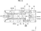
- the first sensor 200a may be detachably mounted on the outer surface of the filter case 110 to detect water accommodated inside the filter case 110.
- the first sensor 200a may be mounted on the outer surface of the filter case 110, corresponding to the second space S2.
- the first sensor 200a may detect water accommodated in the second space S2.
- the first sensor 200a may detect a case in which water entered into the filter case 110 reaches a preset water level inside the filter case 110.
- the first sensor 200a may detect a case in which a water level of water accommodated in the filter case 110 is equal to or higher than a height of the lowest end L of the filter 120.
- FIGS. 10 and 11 show a case in which the first sensor 200a is mounted on the outer surface of the filter case 110, although not limited thereto.
- the first sensor 200a may be detachably mounted on the outer surface of the housing inlet 102a of the filter housing 101.
- the first sensor 200a may be detachably mounted on the outer surface of the inlet guide 106.
- the first sensor 200a is not limited in position as long as the first sensor 200a is capable of detecting water entered into the filter apparatus 100 from the drain device 70 or 70a of the washing machine 10 or 10a.
- FIG. 12 shows a cross section of a filter apparatus including a second sensor according to an embodiment of the disclosure.
- FIG. 13 shows a state in which the second sensor has moved according to reception of water by the filter apparatus shown in FIG. 12 .
- the filter apparatus 100 may include the second sensor 200b.
- the second sensor 200b may be a contact sensor.
- the second sensor 200b may detect water entered into the filter apparatus 100 through a physical contact to water.
- the second sensor 200b may be detachably installed inside the filter case 110 to detect water accommodated in the filter case 100.
- the second sensor 200b may be positioned in the second space S2.
- the second sensor 200b may detect water entered into the second space S2 through the case inlet 112a.
- the second sensor 200b may detect a case in which water entered into the filter case 110 reaches a preset water level inside the filter case 110.
- the second sensor 200b may detect a case in which a water level of water accommodated in the filter case 110 is equal to or higher than a height of the lowest end L of the filter 120.
- the second sensor 200b may include a float 202. At least one portion of the float 202 may be positioned in the second space S2, and float by water entered into the second space S2 through the case inlet 112a.
- the second sensor 200b may include a stem 201 extending from the float 202. According to filling of water in the second space S2, the float 202 may move along an extension direction of the stem 201.
- the float 202 may be movable in an up-down direction.
- the float 202 may include a magnet
- the stem 201 may include a switch. According to floating of the float 202, the magnet of the float 202 may turn on or off the switch of the stem 201.
- a stem fixing portion 115 for fixing the stem 201 may be provided inside the filter case 110.
- the stem fixing portion 115 may restrict the stem 201 with respect to a circumferential direction of the stem 201.
- the stem fixing portion 115 may not restrict the stem 201 with respect to the extension direction of the stem 201. Accordingly, the float 202 may move along the extension direction of the stem 201 by water entered into the second space S2.
- FIG. 14 shows a cross section of a filter apparatus including a third sensor according to an embodiment of the disclosure.
- the filter apparatus 100 includes a third sensor 200c will be described with reference to FIG. 14 .
- the third sensor 200c may correspond to an example of the water supply sensor 200.
- the third sensor 200c may detect water entered into the filter apparatus 100.
- the third sensor 200c may detect water passing through at least one component of the filter apparatus 100.
- the third sensor 200c may detect a rate of flow of water entered into the filter apparatus 100.
- the third sensor 200c may include a rotating body 203.
- the rotating body 203 may be rotatable by water entered into the filter apparatus 100.
- the rotating body 203 may rotate by water passing through the housing inlet 102.
- the rotating body 203 may include a magnet. According to a rotation of the rotating body 203, magnetism of the magnet included in the rotating body 203 may change. According to the change of the magnetism of the magnet included in the rotating body 203, a sensor output of the sensor 200c may also change.
- the sensor 200c may detect at least one among presence or absence of water rotating the rotating body 203, velocity of water rotating the rotating body 203, or a rate of flow of water rotating the rotating body 203, based on the sensor output.
- FIG. 14 shows a case in which the third sensor 200c is installed in the housing inlet 102a, although embodiments are not limited thereto.
- the third sensor 200c may be detachably installed in the inlet guide 106.
- the rotating body 203 of the third sensor 200c may detect water passing through the inlet guide 106.
- the third sensor 200c may be detachably installed in the case inlet 112a of the filter case 110.
- the third sensor 200c may detect water passing through the case inlet 112a.
- the third sensor 200c may be detachably installed in the second space S2.
- the third sensor 200c may detect water passing through the second space S2.
- the third sensor 200c is not limited in position as long as the third sensor 200c is capable of detecting a flow of water entering the filter apparatus 100 from the drain device 70 or 70a of the washing machine 10 or 10a.
- FIG. 15 shows a filter apparatus including a fourth sensor according to an embodiment of the disclosure.
- FIG. 16 shows a cross section of the filter apparatus shown in FIG. 15 .
- FIG. 17 shows a cross section of a filter apparatus in which the fourth sensor shown in FIG. 16 is provided at a location that is different from a location in FIG. 16 .
- FIG. 18 shows a fourth sensor according to an embodiment of the disclosure.
- the filter apparatus 100 includes a fourth sensor 200d will be described with reference to FIGS. 15 to 18 .
- the fourth sensor 200d may correspond to an example of the water supply sensor 200.
- the filter apparatus 100 may include the fourth sensor 200d.
- the fourth sensor 200d may be a contact sensor.
- the fourth sensor 200d may detect water entered into the filter apparatus 100 through a physical contact to water.
- the fourth sensor 200d may be detachably installed in the filter case 110.
- the fourth sensor 200d may detect water accommodated in the filter case 110.
- the fourth sensor 200d may detect water entered into the filter case 110.
- the fourth sensor 200d may detect water passing through at least one component of the filter apparatus 100.
- the fourth sensor 200d may include a first electrode portion 2041 and a second electrode portion 2051. A pair of the first electrode portion 2041 and the second electrode portion 2051 may be provided. The fourth sensor 200d may detect conduction between the first electrode portion 2041 and the second electrode portion 2051. The fourth sensor 200d may detect a short circuit between the first electrode portion 2041 and the second electrode portion 2051. For example, upon a contact of the first electrode portion 2041 and the second electrode portion 2051 to water, current may flow between the first electrode portion 2041 and the second electrode portion 2051. The fourth sensor 200d may identify that water enters the filter apparatus 100 based on the current.
- the first electrode portion 2041 and the second electrode portion 2051 of the fourth sensor 200d may be positioned inside the filter case 110.
- the first electrode portion 2041 may be positioned in the second space S2, and the second electrode portion 2051 may be spaced a preset distance from the first electrode portion 2041.
- the fourth sensor 200d may detect water entered into the second space S2 through the case inlet 112a and moving toward the first space S1.
- the fourth sensor 200d may include a first electrode unit 204 and a second electrode unit 205.
- the first electrode unit 204 may include the first electrode portion 2041 for detecting water.
- the first electrode portion 2041 may include an electrode bar from which a sheath has been peeled off.
- the first electrode portion 2041 may be in contact with water.
- the first electrode portion 2041 may be exposed to inside of the filter case 110, inside of the inlet guide 106, or inside of the housing inlet 102b.
- the first electrode unit 204 may include a first fixing portion 2042 fixed to the filter apparatus 100.
- the first fixing portion 2042 may be provided at one side of the first electrode portion 2041.
- the first fixing portion 2042 may be mounted on the outer surface of the filter case 110, an outer surface of the inlet guide 106, or an outer surface of the housing inlet 102b.
- the first electrode unit 204 may include a first sensor cable 2044.
- the first sensor cable 2044 may be electrically connected to the circuitry 190.
- the first electrode unit 204 may include a holder 2043 provided to support the first sensor cable 2044.
- the second electrode unit 205 may include a second fixing portion 2052 fixed to the filter apparatus 100.
- the second fixing portion 2052 may be provided at one side of the second electrode portion 2051.
- the second fixing portion 2052 may be positioned on the outer surface of the filter case 110, the outer surface of the inlet guide 106, and the outer surface of the housing inlet 102b.
- the second electrode unit 205 may include a holder 2053 for supporting the second sensor cable 2054.
- the fifth sensor 200e may detect a water level of water in the filter case 110.
- the fifth sensor 200e may detect a water level of water flowing inside the filter case 110.
- the fifth sensor 200e may detect a water level of water accommodated in the filter case 110.
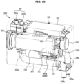
- FIG. 20 shows a filter apparatus according to an embodiment of the disclosure.
- locations of a housing inlet 202a and a housing outlet 202b of the filter apparatus 100a may be different from locations of the housing inlet 102a and the housing outlet 102b of the filter apparatus 100 shown in FIGS. 6 to 9 .
- the housing outlet 202b may be positioned in a rear surface of the filter apparatus 100a.
- the housing outlet 202b may be positioned at the housing bracket.
- the housing outlet 102b of the filter apparatus 100 shown in FIGS. 6 to 8 may be positioned at the housing body 102, whereas the housing outlet 202b of the filter apparatus 100a shown in FIG. 20 may be positioned at the housing bracket.
- the housing outlet 202b may be connected directly to a case outlet 111b.
- the discharge guide 107 may be omitted between the housing outlet 202b and the case outlet 111b.
- the housing outlet 202b and the case outlet 111b may be integrated into one body.
- FIG. 21 is a control block diagram of a filter apparatus according to an embodiment of the disclosure.
- FIG. 21 schematically shows a flow of signals between components of the filter apparatus according to an embodiment of the disclosure.
- the controller 191 may include at least one memory 191a and at least one processor 191b to perform the above-described operations and operations which will be described below.
- the controller 191 may include at least one memory 191a that stores data in the form of an algorithm and/or program for controlling operations of components in the filter apparatus 100 or 100a, and at least one processor 191b that performs the above-described operations and operations which will be described below by using the data stored in the at least one memory 191a.
- the memory 191a and the processor 191b may be implemented with separate chips.
- the processor 191b may include one, two, or more processor chips or one, two, or more processing cores.
- the memory 191a may include one, two, or more memory chips or one, two, or more memory blocks. Also, the memory 191a and the processor 191b may be implemented with a single chip.
- the user interface 197 may include the first button 197a and the second button 197b, and operate based on a control signal from the controller 191.
- the filter sensor 150 may detect an amount of foreign materials collected in the filter 120.
- the filter sensor 150 may transfer a sensing signal to the controller 191.
- the filter sensor 150 may transfer sensor data to the controller 191.
- the filter sensor 150 may be mounted on the filter case 110.
- the water supply sensor 200 may detect supply of water to the filter apparatus 100 or 100a.
- the water supply sensor 200 may transfer a sensing signal to the controller 191.
- the water supply sensor 200 may transfer sensor data to the controller 191.
- the water supply sensor 200 may be installed in the filter case 110.
- the water supply sensor 200 may be installed in the case inlet 112a.
- the water supply sensor 200 may be installed in the inlet guide 106.
- the water supply sensor 200 may be installed in the housing inlet 102a.
- the water supply sensor 200 may include various kinds of sensors. However, the water supply sensor 200 may adopt any configuration capable of detecting supply of water to the filter apparatus 100 or 100a.
- the controller 191 may process sensor data received from the filter sensor 150 and/or the water supply sensor 200, and control various components (for example, the filter cleaning device 130 and the opening and closing device140) of the filter apparatus 100 or 100a based on a result of the processing on the sensor data. It is understood that these various components may be controlled in accordance with a signal produced by the sensors that correspond to, for example, a detected water level in the filter apparatus.
- the filter cleaning device 130 may include the cleaning member 131 inserted in the filter 120 in such a way as to be slidable or rotatable with respect to the inner surface of the filter 120, and the cleaning motor 136 for rotating the cleaning member 131.
- the controller 191 may control the filter cleaning device 130.
- the controller 191 may operate or stop the cleaning motor 136.
- the controller 191 may control a driving circuit for applying driving current to the cleaning motor 136.
- the driving circuit may supply driving current to the cleaning motor 136 in response to a driving signal from the controller 191.
- the driving circuit may include a rectifying circuit for rectifying alternating current power of an external power source, a direct current link circuit for removing ripples from the rectified power and outputting direct current power, an inverter circuit for converting the direct current power into driving power in a form of a sine wave and outputting driving current to the cleaning motor 136, a current sensor for measuring driving current that is supplied to the cleaning motor 136, and a gate driver for turning on/off a switching device included in the inverter circuit based on a driving signal from the controller 191.
- the opening and closing device140 may include the connection door 141 for opening or closing the connecting opening 118, and the door motor 142 for operating the connection door 141.
- the controller 191 may control the opening and closing device140.
- the controller 191 may control an operation of the door motor 142 to open or close the connecting opening 118.
- the communicator 199 may transmit data to an external device based on a control signal from the controller 191, or receive data from an external device. For example, the communicator 199 may transmit/receive various data by communicating with a server and/or a user terminal and/or a home appliance including the washing machine 10 or 10a.
- the communicator 199 may support establishment of a direct (for example, wired) communication channel or a wireless communication channel with an external electronic device (for example, a server, a user terminal, and/or a home appliance), and communications through an established communication channel.
- the communicator 199 may include a wireless communication module (for example, a cellular communication module, a short-range communication module, or a GNSS communication module) or a wired communication module (for example, a LAN communication module or a power line communication module).
- the communicator 199 may establish a communication with a user terminal through a server.
- the communicator 199 may include a WiFi module, and may communicate with an external server and/or a user terminal based on communication establishment with an AP in home.
- the controller 191 may identify that a drain operation of the washing machine 10 or 10a starts. According to a continuous detection of the first condition by the water supply sensor 200, the controller 191 may identify that a drain operation of the washing machine 10 or 10a is in progress. For example, in a case in which the water supply sensor 200 fails to detect the first condition for a preset time after detecting the first condition, the controller 191 may identify that a drain operation of the washing machine 10 or 10a has terminated. For example, according to a detection of a second condition by the water supply sensor 200, the controller 191 may identify that a drain operation of the washing machine 10 or 10a has terminated.
- the flowchart shown in FIG. 23 may be not intended to limit an order of operations 2100, 2200, 2300, 2400, 2500, and 2600, and the order of operations 2100, 2200, 2300, 2400, 2500, and 2600 may change according to various embodiments of the disclosure.
- At least two of operations 2100, 2200, 2300, 2400, 2500, and 2600 may be performed simultaneously.
- the filter cleaning device 130 may operate for a first time a. After the filter cleaning device 130 operates for the first time a, the filter cleaning device 130 may stop for a second time b. After the filter cleaning device 130 stops for the second time b, the filter cleaning device 130 may operate for a third time c. After the filter cleaning device 130 operates for the third time c, the filter cleaning device 130 may stop for a fourth time d. After the filter cleaning device 130 operates for the first time a and stops for the second time b, the filter cleaning device 130 may operate according to a period of a fifth time e. The fifth time e may be a sum of the third time c and the fourth time d.
- FIG. 26 shows an example in which the driving current A of the cleaning driving device 135 changes periodically, although not limited thereto.
- the driving current A of the cleaning driver 135 may change irregularly over time.
- the driving current A of the cleaning driver 135 may change regularly for a preset period and change irregularly for another preset period.
- a time at which drainage of the washing machine starts may be set by the controller 191 of the filter apparatus 100.
- a time at which drainage of the washing machine terminates may be set by the controller 191 of the filter apparatus 100.
- the filter apparatus 100 may receive information about a drainage start time and/or a drainage termination time of the washing machine 10 or 10a by communicating with the washing machine 10 or 10a.
- the controller may operate the cleaning driver based on a detection of a preset condition by the sensor.
- the preset condition may include a case in which a water level of water accommodated in the filter case is equal to or higher than a height of a lowest end L of the filter.
- the controller may stop operating the cleaning driver based on a detection of a preset condition by the sensor.
- the filter case 110 may form a first space S1 in which the filter is installed, and a second space S2 positioned below the first space and accommodating water received through the case inlet and flowing toward the first space.
- the sensor 200 may detect at least one of water passing through the case inlet or water accommodated in the second space.
- the cleaning driver may include a cleaning motor 136.
- the filter cleaning device may include a cleaning member 131 that receives power of the cleaning motor and is rotatable while being in contact with a surface of the filter through which foreign materials are filtered.
- An external diameter of the cleaning member 131 may be greater than an internal diameter of the filter.
- the sensor may be mounted on an outer surface of the filter case, corresponding to the second space, and detect water accommodated in the second space.
- the sensor may include a float 202 of which at least one portion is positioned in the second space and which floats by water received through the case inlet.
- the sensor may include a rotating body 203 positioned in the case inlet and being rotatable by water passing through the case inlet.
- the sensor may include a first electrode portion 2041 positioned in the case inlet, and a second electrode portion 2051 spaced from the first electrode portion, and may detect conduction between the first electrode portion and the second electrode portion.
- a clothes treating apparatus 1 or 1a may include a washing machine 10 or 10a and a filter apparatus 100 or 100a.
- the washing machine may include a washing machine housing, a tub provided inside the washing machine housing, and a drain device for discharging water stored in the tub to outside of the washing machine housing.
- the filter apparatus may be positioned outside the washing machine housing, and connectable to the drain device of the washing machine.
- the filter apparatus may include a filter case 110, a filter 120 being detachably installable in the filter case, a filter cleaning device 130 including a cleaning driver 135 configured to clean the filter, a sensor 200 configured to detect water entered into the filter apparatus, and a controller 191 configured to control an operation of the filter cleaning device based on information obtained through the sensor.
Landscapes
- Chemical & Material Sciences (AREA)
- Chemical Kinetics & Catalysis (AREA)
- Engineering & Computer Science (AREA)
- Textile Engineering (AREA)
- Detail Structures Of Washing Machines And Dryers (AREA)
Applications Claiming Priority (3)
| Application Number | Priority Date | Filing Date | Title |
|---|---|---|---|
| KR20220099534 | 2022-08-09 | ||
| KR1020220182344A KR20240021089A (ko) | 2022-08-09 | 2022-12-22 | 필터장치 및 필터장치를 갖는 의류 처리 장치 |
| PCT/KR2023/007134 WO2024034793A1 (fr) | 2022-08-09 | 2023-05-25 | Appareil de filtration et appareil de traitement de vêtements le comprenant |
Publications (2)
| Publication Number | Publication Date |
|---|---|
| EP4534754A1 true EP4534754A1 (fr) | 2025-04-09 |
| EP4534754A4 EP4534754A4 (fr) | 2025-11-05 |
Family
ID=89846841
Family Applications (1)
| Application Number | Title | Priority Date | Filing Date |
|---|---|---|---|
| EP23852688.3A Pending EP4534754A4 (fr) | 2022-08-09 | 2023-05-25 | Appareil de filtration et appareil de traitement de vêtements le comprenant |
Country Status (3)
| Country | Link |
|---|---|
| US (1) | US20240052546A1 (fr) |
| EP (1) | EP4534754A4 (fr) |
| CN (1) | CN119546812A (fr) |
Families Citing this family (1)
| Publication number | Priority date | Publication date | Assignee | Title |
|---|---|---|---|---|
| US12427453B2 (en) * | 2022-11-25 | 2025-09-30 | Samsung Electronics Co., Ltd. | Microplastic filter for washing machines or other appliances |
Family Cites Families (7)
| Publication number | Priority date | Publication date | Assignee | Title |
|---|---|---|---|---|
| KR101645040B1 (ko) * | 2010-03-31 | 2016-08-02 | 엘지전자 주식회사 | 식기 세척기 및 그 제어 방법 |
| KR102046694B1 (ko) * | 2017-08-22 | 2019-11-19 | 주식회사 영인 | 자체 세척 스크린 장치 |
| EP3701079B1 (fr) * | 2017-10-25 | 2022-03-02 | E.G.O. Elektro-Gerätebau GmbH | Procédé permettant de faire fonctionner une machine à laver et machine à laver |
| WO2020251512A2 (fr) * | 2019-06-14 | 2020-12-17 | Arcelik Anonim Sirketi | Machine à laver comprenant un élément de filtration |
| GB2592196A (en) * | 2020-02-18 | 2021-08-25 | Cleaner Seas Group Ltd | Micro-fibre filter cartridge |
| DE102020210389A1 (de) * | 2020-08-14 | 2022-02-17 | BSH Hausgeräte GmbH | Fluidführendes Haushaltsgerät |
| DE102020215691A1 (de) * | 2020-12-11 | 2022-06-15 | BSH Hausgeräte GmbH | Filtersystem für ein wasserführendes haushaltsgerät, wasserführendes haushaltsgerät und verfahren zum ableiten von fluid aus einem behandlungsraum |
-
2023
- 2023-05-25 EP EP23852688.3A patent/EP4534754A4/fr active Pending
- 2023-05-25 CN CN202380056109.4A patent/CN119546812A/zh active Pending
- 2023-06-16 US US18/210,811 patent/US20240052546A1/en active Pending
Also Published As
| Publication number | Publication date |
|---|---|
| CN119546812A (zh) | 2025-02-28 |
| US20240052546A1 (en) | 2024-02-15 |
| EP4534754A4 (fr) | 2025-11-05 |
Similar Documents
| Publication | Publication Date | Title |
|---|---|---|
| KR101781536B1 (ko) | 세탁기 및 세탁기 제어방법 | |
| JP2020505201A (ja) | 洗濯機から乾燥機へ、および乾燥機から外側の洗濯物かごへ衣服を自動的に移動させることができる遠隔制御可能な洗濯乾燥機システム | |
| EP4528004A1 (fr) | Dispositif de filtration et appareil de traitement de vêtements doté d'un dispositif de filtration | |
| US20250066984A1 (en) | Washing machine and controlling method of washing machine | |
| JP4584020B2 (ja) | ドラム式洗濯機 | |
| EP4534754A1 (fr) | Appareil de filtration et appareil de traitement de vêtements le comprenant | |
| US12584263B2 (en) | Washing machine and controlling method of washing machine | |
| EP4528015A1 (fr) | Appareil de filtration et appareil de traitement de vêtements le comprenant | |
| EP4632136A2 (fr) | Appareil de traitement de vêtements | |
| EP4528016A1 (fr) | Dispositif de filtre | |
| KR20240021087A (ko) | 필터장치 및 필터장치를 갖는 의류 처리 장치 | |
| KR20240021088A (ko) | 필터장치 및 필터장치를 갖는 의류 처리 장치 | |
| KR20240021089A (ko) | 필터장치 및 필터장치를 갖는 의류 처리 장치 | |
| KR20240177656A (ko) | 필터장치 및 필터장치의 제어방법 | |
| EP4541960A1 (fr) | Appareil de filtre et son procédé de gestion | |
| US20230416964A1 (en) | Washing machine and controlling method of washing machine | |
| US20250367583A1 (en) | Filter apparatus and clothes treating apparatus having same | |
| EP4488439A1 (fr) | Machine à laver et appareil de traitement de vêtements | |
| KR20240168811A (ko) | 필터장치 및 의류 처리 장치 | |
| US20250188667A1 (en) | Filter module, filter apparatus, and clothes treating apparatus | |
| KR20240075633A (ko) | 필터장치 및 필터장치의 관리방법 | |
| KR20240177279A (ko) | 의류 처리 장치 | |
| EP4461863A1 (fr) | Lave-linge et procédé de commande de lave-linge | |
| KR20240021090A (ko) | 필터장치 | |
| CN118742681A (zh) | 洗衣机和洗衣机控制方法 |
Legal Events
| Date | Code | Title | Description |
|---|---|---|---|
| STAA | Information on the status of an ep patent application or granted ep patent |
Free format text: STATUS: THE INTERNATIONAL PUBLICATION HAS BEEN MADE |
|
| PUAI | Public reference made under article 153(3) epc to a published international application that has entered the european phase |
Free format text: ORIGINAL CODE: 0009012 |
|
| STAA | Information on the status of an ep patent application or granted ep patent |
Free format text: STATUS: REQUEST FOR EXAMINATION WAS MADE |
|
| 17P | Request for examination filed |
Effective date: 20250103 |
|
| AK | Designated contracting states |
Kind code of ref document: A1 Designated state(s): AL AT BE BG CH CY CZ DE DK EE ES FI FR GB GR HR HU IE IS IT LI LT LU LV MC ME MK MT NL NO PL PT RO RS SE SI SK SM TR |
|
| A4 | Supplementary search report drawn up and despatched |
Effective date: 20251006 |
|
| RIC1 | Information provided on ipc code assigned before grant |
Ipc: D06F 39/10 20060101AFI20250929BHEP Ipc: D06F 34/20 20200101ALI20250929BHEP Ipc: B01D 35/16 20060101ALI20250929BHEP Ipc: D06F 103/14 20200101ALI20250929BHEP Ipc: D06F 105/34 20200101ALI20250929BHEP |
|
| DAV | Request for validation of the european patent (deleted) | ||
| DAX | Request for extension of the european patent (deleted) |