EP4534774A1 - Dachfenster mit einem rahmen mit einer dichtungsmuffe und einem dichtungselement sowie verfahren zur abdichtung einer verbindung zwischen einem dachfenster und einer dachstruktur - Google Patents
Dachfenster mit einem rahmen mit einer dichtungsmuffe und einem dichtungselement sowie verfahren zur abdichtung einer verbindung zwischen einem dachfenster und einer dachstruktur Download PDFInfo
- Publication number
- EP4534774A1 EP4534774A1 EP24204128.3A EP24204128A EP4534774A1 EP 4534774 A1 EP4534774 A1 EP 4534774A1 EP 24204128 A EP24204128 A EP 24204128A EP 4534774 A1 EP4534774 A1 EP 4534774A1
- Authority
- EP
- European Patent Office
- Prior art keywords
- frame
- sealing
- flashing
- socket
- interior
- Prior art date
- Legal status (The legal status is an assumption and is not a legal conclusion. Google has not performed a legal analysis and makes no representation as to the accuracy of the status listed.)
- Pending
Links
Images


Classifications
-
- E—FIXED CONSTRUCTIONS
- E04—BUILDING
- E04D—ROOF COVERINGS; SKY-LIGHTS; GUTTERS; ROOF-WORKING TOOLS
- E04D13/00—Special arrangements or devices in connection with roof coverings; Protection against birds; Roof drainage ; Sky-lights
- E04D13/14—Junctions of roof sheathings to chimneys or other parts extending above the roof
- E04D13/147—Junctions of roof sheathings to chimneys or other parts extending above the roof specially adapted for inclined roofs
- E04D13/1473—Junctions of roof sheathings to chimneys or other parts extending above the roof specially adapted for inclined roofs specially adapted to the cross-section of the parts extending above the roof
- E04D13/1475—Junctions of roof sheathings to chimneys or other parts extending above the roof specially adapted for inclined roofs specially adapted to the cross-section of the parts extending above the roof wherein the parts extending above the roof have a generally rectangular cross-section
-
- E—FIXED CONSTRUCTIONS
- E04—BUILDING
- E04D—ROOF COVERINGS; SKY-LIGHTS; GUTTERS; ROOF-WORKING TOOLS
- E04D13/00—Special arrangements or devices in connection with roof coverings; Protection against birds; Roof drainage ; Sky-lights
- E04D13/03—Sky-lights; Domes; Ventilating sky-lights
- E04D13/0305—Supports or connecting means for sky-lights of flat or domed shape
- E04D13/031—Supports or connecting means for sky-lights of flat or domed shape characterised by a frame for connection to an inclined roof
-
- E—FIXED CONSTRUCTIONS
- E04—BUILDING
- E04D—ROOF COVERINGS; SKY-LIGHTS; GUTTERS; ROOF-WORKING TOOLS
- E04D13/00—Special arrangements or devices in connection with roof coverings; Protection against birds; Roof drainage ; Sky-lights
- E04D13/03—Sky-lights; Domes; Ventilating sky-lights
- E04D13/035—Sky-lights; Domes; Ventilating sky-lights characterised by having movable parts
- E04D13/0351—Sky-lights; Domes; Ventilating sky-lights characterised by having movable parts the parts pivoting about a fixed axis
- E04D13/0354—Sky-lights; Domes; Ventilating sky-lights characterised by having movable parts the parts pivoting about a fixed axis the parts being flat
Definitions
- the present invention relates to a roof window configured for being mounted in a roof structure comprising a roofing material, said roof window comprising a frame and a sash carrying a pane, where the frame comprises a plurality of frame members together defining a frame opening and a frame plane and each frame member extends in a length direction and a height direction, which height direction is perpendicular to the frame plane.
- the invention further relates to a method for weatherproofing a joint between a roof window and a roof structure.
- each flashing member having a first leg extending along an outer side of the frame of the roof window and a second leg extending over the roof structure, thereby bridging and covering any gaps present between the roof window and the roofing material.
- Flashing members are usually attached both to the frame of the roof window and to the roof structure. This is easily done when both the roof window frame and the roof structure are made from wood, and the roof window projects above the roofing material, but there is a desire for alternative solutions allowing a wider range of applications.
- a roof window where at least one of the frame members comprises a flashing socket extending in the length direction of the at least one frame member and having a socket opening facing away from the frame opening, which flashing socket houses a separate sealing member extending in the length direction of the at least one frame member and forming a sealing groove having a groove opening facing away from the frame opening; said flashing socket having an interior face facing away from the roof structure, an exterior face facing toward the roof structure and an end face positioned opposite to the flashing socket opening; and said sealing member having an interior leg associated with the interior face of the flashing socket, and an exterior leg associated with the exterior face of the flashing socket, and an end leg associated with the end face of the flashing socket; wherein the sealing member is provided with a plurality of sealing protrusions configured for engaging the least one flashing member when the flange of the flashing member is received in the sealing groove.
- a flange of at least one flashing member can be received in the sealing groove allowing the flashing members to be attached without the use of screws or like fasteners penetrating into the material of the frame member.
- the sealing member may both contribute to weather-proofing and to holding the flashing member by friction, but additional attachment may be preferred or necessary.
- a position or structure is said to be “interior” when it is positioned toward the roof structure in an installed state of the roof window as seen in the height direction and is said to be “exterior” when it is positioned toward an exterior of a building comprising the roof structure, also as seen in the height direction.
- a frame member may be an integrally formed member.
- a frame member may comprise multiple profiles attached to each other so as to form the frame member, such as a metal or plastic profile attached to a wooden profile.
- the flashing socket for the sealing member may conceivably be provided in any of such profiles, but it may be preferred that the flashing socket is provided close to an exterior surface of the frame member, such that the flashing covers a majority of an outer side of the frame member extending above the roof structure.
- the sash may be movable in relation to the frame, i.e. the window is openable, by way of a hinge.
- At least one sealing protrusion of the plurality of sealing protrusions is an outward sealing protrusion which protrudes from the groove opening in a direction away from the frame opening.
- Such an outward sealing protrusion may engage the flashing member at a position outside of the sealing groove of the sealing member, providing additional sealing and/or an improved engagement with the flashing member.
- an outward sealing protrusion may serve to deflect wind, water, and dirt away from the groove opening and/or from an opening in the frame member. Such an outward sealing protrusion will typically extend from an edge of the interior leg of the sealing member at the groove opening.
- flashing members may generally comprise an L-shape having a first leg for extending upwards along an outer side of the frame away from the roof structure and a second leg for extending outwards over the roof structure away from the frame.
- a flashing member for use with the roof window according to the invention will also comprise a flange extending to be received in the sealing groove, i.e. at an angle to the first leg, typically in parallel to the second leg.
- An outward sealing protrusion extending from an edge of the interior leg of the sealing member at the groove opening may engage the first leg of such a flashing member. This may especially be advantageous for flashing installations, where two or more flashing members are arranged partially overlapping along the length of the frame member.
- At least one sealing protrusion of among the plurality of the sealing protrusions is an interior inwards sealing protrusion, which interior sealing protrusion is positioned on the interior leg of the sealing member and protrudes into the sealing groove.
- the interior inwards sealing protrusion extends in a direction toward the frame opening. In this way the interior inwards sealing protrusion engages the flange of the flashing member from below.
- the interior inwards sealing protrusion may extend from the edge of the interior leg.
- the interior inwards sealing protrusion forms an angle to the frame plane, which angle may be in the range of 15 to 60 degrees, preferably 20 to 55 degrees, more preferably 25 to 50 degrees.
- the interior inwards sealing protrusion may extend in parallel continuation of the outwards sealing protrusion, whereby the angles formed by said two protrusions to the frame plane are substantially equal.
- the interior inwards sealing protrusion may have a length such that it extends at least 50 % of a height of the sealing groove, preferably 50 to 70 % of the height of the sealing groove. This is understood to mean that if the length of the interior inwards sealing protrusion and the height of the groove opening are projected onto the height direction, the former forms at least 50 % of the latter.
- the height of the sealing groove may be the height of the part of the end leg of the sealing member which delimits the sealing groove.
- the interior inwards sealing protrusion may be the only sealing protrusion protruding into to the sealing groove from the interior leg. It has been found that a single interior inwards sealing protrusion on the interior leg formed as described above, provides good sealing performance by itself at this position. In this way the sealing member design is simplified, and manufacturing cost and complexity is reduced compared to a sealing member having several sealing protrusions on the interior leg.
- both the exterior inward sealing protrusions and one or more interior inward sealing protrusions project towards the frame opening, they may form a funnel shape, guiding the flange into place in the sealing groove.
- the exterior inward sealing protrusions may be minor protrusions as described above. It is generally preferred for the exterior inwards protrusions and the interior inwards protrusion(s) to have a length so as to form an overlap in the height direction to ensure a tight contact between the sealing member and the flange of the flashing member.
- a first of the exterior inwards sealing protrusions is preferably position at an exterior edge of the exterior leg of the sealing member, which exterior edge extends at the groove opening.
- a number of sealing protrusions which are positioned on the exterior leg of the sealing member and protrude into the sealing groove, exceeds a number of sealing protrusions, which are positioned on the interior leg and protrude into the sealing groove.
- the sealing protrusions are said to be arranged asymmetrically. In this way the number of protrusions is minimized while still providing the desired sealing effect, thereby potentially reducing material consumption and cost.
- the sealing member may comprise a weakening, such as an indentation, which facilitates a collapse of the sealing member as it is inserted into the flashing socket.
- the weakening may extend in the length direction.
- the weakening may be formed in the end leg of the sealing member, whereby the exterior and interior legs of the sealing approach each other as the sealing member collapses.
- Sealing members are generally made from a resilient material, allowing the sealing member to assume a non-collapsed state once the insertion in the flashing socket is complete, and thus engage the flashing socket.
- an indentation in the end leg is provided in a surface of the sealing member facing the sealing groove, it may be positioned such that the flange of the flashing member is received in the indentation when fully inserted, thereby also providing a further seal and/or contributing to positioning the flange.
- An indentation in the sealing member may be formed in a surface facing the flashing socket, which may also facilitate fitting of the sealing member into the flashing socket.
- This indentation may be formed at a junction between two of the legs of the sealing member, preferably at the junction of the interior leg and the end leg.
- a separate supplemental sealing member housed in the supplemental socket has an anchoring section, which extends into the supplemental socket.
- the supplemental sealing member further comprises an exterior section extending away from the roof structure and configured for sealing against a covering member or a cladding member of a cladding assembly.
- the cladding assembly is provided to cover the sash of the roof window toward the exterior, the cladding members covering joints between sash members and frame members and the covering members extending between the cladding members and the covering members.
- the sash comprise sash profile elements, where a second sash profile element is positioned above the frame and covers the frame toward the exterior, and in such roof windows the exterior section of the supplemental sealing member may sealing against this second sash profile element.
- An exterior sealing section of a second sealing member may engage an inwards face of a cladding member (or second sash profile element), which inwards face faces towards the frame opening.
- this is achieved by an exterior section comprising a first leg extending inwards toward the frame opening and a second leg extending outwards from an inwards end of the first leg, away from the roof structure and the frame opening, preferably at an acute angle with respect to the first leg.
- the exterior section may alternatively engage a most interior point of an outer portion of the cladding member or second sash profile element, which outer portion forms an outer side of the cladding member or second sash profile element facing away from the frame opening.
- the supplemental sealing member may further comprise an interior sealing section extending from the anchor section toward the roof structure and configured for engaging the flange of the flashing member when this is inserted into the flashing socket.
- the interior sealing section is configured to extend across at least part of the flashing socket opening of the flashing socket whereby insertion of the flange of the flashing member into the first sealing member pushes the interior sealing section of the supplemental sealing member into the flashing socket, providing a seal between flashing socket and flange.
- the flashing and supplemental sockets with their respective sealing members thus provide a complete sealing assembly for sealing the joint between frame and roof structure and the joint between frame and sash, respectively.
- This sealing assembly may allow for reducing the size of the cladding members, or second sash profile elements, while maintaining weatherproofing, which is desirable in some roof window designs. If the roof window is fixed, i.e. the sash is not able to move relative to the frame, the sealing members of the flashing socket and supplemental socket may be integrally formed.
- an exterior side this relates to a side of a roof window in a mounted condition facing the outdoors or external side of the building.
- an interior side refers to a side facing the internal side of the building, i.e. typically a subjacent room including any light shaft.
- Terms such as “outwards” and “inwards” are directions generally perpendicular to an interior-exterior direction, taking as its base point a centre of the roof window.
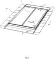
- a roof window 1 is shown.
- the roof window 1 is intended to be installed in an inclined roof surface (not shown).
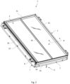
- the roof window 1 comprises a frame 2, a sash 3, and a pane 4.
- the frame 2 comprises a set of frame members including a top frame member 21, two side frame members 22, 23 and a bottom frame member 24.
- the sash 3 comprises a set of sash members including a top sash member 31, two side sash members 32, 33 and a bottom sash member 34. While the frame 2 and sash 3 are described as rectangular structures, some principles of the presented concepts may be applicable to other geometrical shapes as well.
- An interior pane surface faces the interior, typically a room of a building subjacent the roof surface in which the roof window 1 is installed.
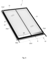
- a glazing bar 45 is fitted to the exterior surface of the pane. It is conceivable to fit a counterpart glazing bar cover on the interior pane surface. Although less practical, it would also be possible to have a two-part pane with two pane halves divided by a throughgoing glazing bar. In wide roof windows, it is also possible to have more than one glazing bar, for instance two glazing bars dividing the surface of the pane visible from the exterior into three sections etc.
- the pane 4 is in the embodiment shown as a two-layer insulating glazing unit, but may comprise three layer, or be a single-sheet glazing unit, or a vacuum insulated glass.
- the pane 4 may be stepped, i.e. an exterior sheet comprises an extended portion extending beyond a bottom edge portion of an interior sheet.
- FIGs 1 and 2 Further details shown in Figs 1 and 2 include an operating assembly 5, here shown as a manual handwinder or screwjack. Other operating assemblies may be present as well.
- an operating assembly 5 here shown as a manual handwinder or screwjack.
- Other operating assemblies may be present as well.
- Insulation by an insulating frame is optional and may be provided along only some of the frame members or as shown surrounding all four frame members 21, 22, 23, 24.
- the side sash member 32 comprises a first sash profile element 32p1 and the side frame member 22 comprises a first frame profile element 22p1 and a second frame profile element 22p2.
- first sash profile element 32p1 and first frame profile element 22p1 is formed by a continuous moulding process.
- the first sash profile element 32p1 and the first frame profile element 22p1 are formed by extrusion of a thermoplastic material, here polyvinyl chloride (PVC).
- PVC polyvinyl chloride
- Other manufacturing methods and polymer materials may be suitable as well.
- the second frame profile element 22p2 comprises an interface section 8 configured to interact with one or more external components.
- the second frame profile element 22p2 is a substantially L-shaped metal component with an outer end comprising the interface section 8.
- the side sash member 32 comprises a second sash profile element 32p2 in addition to the first sash profile element 32p1.
- Fig. 4 shows an alternative embodiment of the invention
- the side sash member 32 is composed by only the first sash profile element 32p1.
- the second sash profile element 32p2 is provided as a longitudinal profile of a metal material, here aluminium but could also be steel or another metal.
- the first sash profile element 32p1 which is here the only constituent main component of the sash member 32, is provided with a metal colouring on the surfaces visible to the exterior.
- the metallic look could be achieved by a metal coating or film and be present on all surfaces facing the exterior.
- first or second sash profile elements are provided by a metal material, or by a plastic or composite material, it is also possible to combine materials in a continuous manufacturing process such as co-extrusion, co-moulding etc. by the addition of heat or light reflective or absorbing elements.
- first sash profile element 32p1 and the first frame profile elements 22p1 each comprises a reinforcement element 22r, 32r in the embodiments shown.
- reinforcement elements are suitable for offering reinforced fastening support but may also be used as strengthening elements to increase the stiffness and resistance to bending.
- the reinforcement element 22r in the frame side member 22 is accommodated in the space formed between one of the dividing walls 22w and the outer circumferential wall of the first frame profile element 22p1 and primarily functions as a fastening support of the second frame profile element 22p2.
- the reinforcement element 22r may be an elongate element extending substantially throughout the length of the frame side member 22 or be in the form of intermittently positioned pieces.
- the reinforcement element 32r of the sash side member 32 functions primarily as a fastening support for the second sash profile element 32p2.
- the reinforcement element 32r has a larger extension in the height direction compared to the Fig. 3 counterpart and thus adds to the stiffness and integrity of the side sash member 32 to provide additional support to portions of the side sash member 32 encasing the pane 4.
- FIG. 6 One example of an embodiment, in which such interface units are incorporated at the top and sides of the roof window 1 is shown in Fig. 6 .
- the second frame profile element 21p2 of the frame top member 21 and the second frame profile element 23p2 of the other frame side member 23 are indicated as well.
- the interface sections at the top and sides are configured to cooperate with external flashing assembly, in a way corresponding to the side flashing member 1012 shown in Fig. 5 .
- a further detail of the embodiment shown in Fig. 6 includes that the interface section 8 of the second frame profile element 24p2 of the bottom frame member 24 forms part of the covering assembly 10 itself, namely by constituting a bottom flashing member 1014.
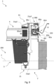
- Fig. 7 an embodiment is shown in which the second sash profile element 32p2 of the side sash member 3 is formed by an extruded metal material which is connected to the first sash profile element 32p1 which is here formed by pultrusion, i.e. another continuous moulding process than the extruded PVC profiles of the embodiments shown in Figs. 3 to 5 .
- the first sash profile element 32p1 is formed by pultrusion of a composite material incorporating resin and glass fibre.
- an inner element 32c of for instance wood is provided and connected to the first sash profile element 32p1 which thereby acts as an intermediate element.
- FIG. 7 shows a cross-section of a roof window 1 where the frame 2 comprises a flashing socket 85 which houses a separate sealing member 85s which forms a sealing groove in which a flange 1017 of a side flashing member 1012 is arranged.
- Fig. 8 shows details of a similar roof window.
- Figs 9 and 10 show similar views but of the top of the roof window 1 corresponding to view IX in Figs 1 and 2 . These figures are described collectively.
- the flashing socket 85 is provided is provided in an interface section 8 of the frame 2, which interfaces with second sash profile elements 31p2, 32p2 covering the frame member which forms part of the frame 2.
- One or more of the interior face 851, end face 852 and exterior face 853 may be provided with ribs 851r, 852r that protrude into the flashing socket 85 and engage the sealing member 85s as show in Figs. 7 and 8 .
- the ribs extend along the flashing socket 85 in the length direction. Providing these ribs provide a drainage channels in between the ribs for draining away water, such as condensate. The ribs may also facilitate mounting the sealing member 85s in the flashing socket 85.
- the sealing member 85s in the flashing socket 85 also has an opening (also at 85b) facing away from the frame opening 200 allowing the flashing member to be inserted in a sealing groove defined by the sealing member.
- the position of the sealing groove is also at reference 85.
- the sealing member 85s has an interior leg 85s1 which is associated with the interior face 851 of the flashing socket 85, i.e. it engages the interior face 851.
- an end leg 85s2 is associated with the end face 852 and an exterior leg 85s3 is associated with the exterior face 853.
- the sealing member 85s is provided a plurality of the sealing protrusions which engage the flashing member 1012 or diverter rail 103 received in the sealing member 85s.
- the outwards sealing protrusion 85o forms an angle a1 with the frame plane F, which in this embodiment is about 30 degrees.
- the angle a1 is measured in a state wherein the outwards sealings protrusion is not deformed by the flashing member 1012.
- the interior leg 85s1 of the sealing member 85s further comprise an interior inwards sealing protrusion 85i which protrudes into the sealing groove toward the frame opening 200.
- the interior inwards sealing protrusion 85i engages the flange 1017 received by the sealing member 85s from below.
- sealing protrusions refer to an undeformed state of the sealing member and its protrusions, i.e. when the flashing members are not inserted in the sealing groove.
- the exterior leg 85s3 of the sealing member is provided with two exterior inwards sealing protrusions 85e which form the remaining sealing protrusions of the sealing member 85s.
- the exterior inwards sealing protrusions 85e protrude into the sealing groove toward the frame opening 200 and at an angle a2 to the frame plane F.
- the angle a2 is these embodiments about 60 degrees as shown in Fig. 10 . It is advantageous that the number of sealing protrusions on the exterior leg 85s3 which protrude into the sealing groove exceeds the number of sealing protrusions on the interior leg 85s1 which protrude into the sealing groove, as the top of the flashing is more exposed.
- the interior leg is provided with the single interior inwards sealing protrusion 85i and the exterior leg 85s3 is provided with at least two exterior inwards sealing protrusions 85e.
- the exterior inwards sealing members 85e are here minor sealing protrusion, the length of which, when projected on to the height direction, extends less than 50 % of the height H85s2 of the sealing groove.
- the sealing protrusions of the sealing member 85 are arranged to overlap in the space where the flange 1017 of the flashing member 1012 is received.
- the sealing member 85s is provided with structures to facilitate fitting the sealing member 85s into the flashing socket 85.
- Indentation 85w2 is provided in the end leg 85s2 and extends along the length of the sealing member 85s.
- the indentation is a weakening of the sealing member, which allows the sealing member 85s to collapse when inserting the sealing member 85s into the flashing socket 85.
- the indentation 85w2 may also form a track to receive the part of the flashing member which is inserted into the sealing member 85s, increasing the sealing effect of the sealing member 85s.
- the indentation 85w2 is preferably arranged at a position in the height direction, at which the flange 1017 of the flashing member 1012 is received by the sealing member 85s.
- Another indentation 85w1 is provided in a surface of the sealing member 85s which faces the flashing socket 85.
- the indentation 85w1 is provided at junction of the interior leg 85s1 and end leg 85s2 of the sealing member. This indentation 85w1 facilitates fitting the sealing member, provided a track for air displacement during fitting of the sealing member, which is especially helpful for embodiments of the flashing socket 85 without ribs 851r1, 852r as in Fig. 9 .
- the interface section 8 which is here embodied by profile elements 22p2, also has a supplemental socket 854 above the opening 85b of the flashing socket 85 as seen in the height direction.
- the supplemental socket 854 is positioned to overlap with the flashing socket 85, thereby reducing a height H85b of the opening 85b of flashing socket 85 compared the height of the end face 852 of the flashing socket 85. This helps retaining the sealing member 85s in the flashing socket 85.
- the supplemental socket 854 is fitted with a supplemental sealing member 854s which has an anchor section 854a extending into the supplemental socket 854 to retain it therein.
- the supplemental socket 854 further has an interior section 85i which extends toward the roof structure (not shown) to engage the flange 1017 of the flashing member 1012.
- the interior section 854i can deform such that it extends into the flashing socket 85 along the flange 1017 as shown in Fig. 7 . This is enabled by an indentation positioned between the interior section 854 and anchor section 854a as shown in Fig. 8 .
- the supplemental sealing socket 854s further has an exterior section 854e which extends away from the roof structure (not shown) and engages the profile element 31p2, 32p2 to seal a gap between the frame 2 and the profile element 31p2, 32p2.
- the exterior section 854e is formed by two segments extending at angle to each other to achieve the desired point of contact to the second sash profile elements 31p2, 32p2.
- the point of contact is here the part of the profile elements 31p2, 32p2 which is proximal to the frame 2 and forms an outer side of the profile elements 31p2, 32p2 and is most interior (i.e. proximal to the frame 2).
- connection implies that the component in question is in a condition, state or position in which the component in question is in fact connected to a part, whereas “connectable to” is intended to encompass such conditions, states and positions in which the component in question may be connected to the relevant part but is not necessarily in connection with the part.
- the hinge assembly 9 comprises a hinge unit and a coupling unit as will be described in the following, in which the coupling unit is connected the hinge unit in the mounted condition and comprises locking means to prevent unintentional release of the connection between the sash 3 and the frame 2.
- the hinge assembly 9 is located within an outer circumference of the frame 2 and sash 3, meaning that no parts of the hinge assembly 9 protrude beyond the periphery of the roof window 1 in the mounted condition.
- the top sash member 31 comprises an exterior or second sash profile element 31p2 and an interior or first sash profile element 31p1
- the top frame member 21 comprises an interior or first frame profile element 22p1 formed by a continuous moulding process, and an exterior or second frame profile element 22p2.
- the exterior sash profile element 31p2 of the top sash member 31 overlaps the associated interior frame profile element 22p1 of the top frame member 21 in the closed position and in the open position of the sash 3.
- the hinge unit of the hinge assembly 9 comprises a frame hinge part 21hp formed in the second frame profile element 21p2 of the frame top member 21 and a sash hinge part 31hp formed in the second sash profile element 31p2 of the sash top member 31.
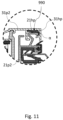
- FIG. 12 the general concept of providing the hinge assembly 9 with a hinge unit 91 which in an installation position is connected to the sash 3 and a coupling unit 95 which is connected to the frame 2 is illustrated.
- the hinge unit 91 is brought into engagement with the coupling unit 95, thereby ensuring the connection between the sash 3 and the frame 2.
- the hinge unit 91 thus comprises a frame hinge part 92 connected to or connectable to the top frame member 21 and/or the side frame member 22, 23 and a sash hinge part 93 connected to the top sash member 31 and/or the side sash member 32, 33.
- the coupling unit 95 of the hinge assembly 9 is connected to or connectable to the frame 2 and configured to be connected to the hinge unit 91 in the mounted condition of the roof window 1.
- the coupling unit 95 comprises a top frame coupling plate 96 connected to the frame 2 at a top corner of the top frame member 21 and one side frame member 23.
- the frame hinge part 92 and the sash hinge part 93 each comprises an angled plate section 928, 929 at the hinge pin 94.
- the top frame coupling plate 96 comprises a first coupling plate receiving structure 968a and a second coupling plate receiving structure 968b to receive a frame hinge part guide pin 928a and a frame hinge part engagement means 928b, respectively, to provide the locking means preventing unintentional release of the connection between the sash 3 and the frame 2 in the mounted condition.
- the top frame coupling plate 96 is shown in broken lines to illustrate the engagement between the coupling unit 95 and the hinge unit 91 more clearly.
- the sash 3 with the hinge unit 91 is brought into a suitable position to allow the frame hinge part guide pin 927a to enter into engagement with the first coupling plate receiving structure 968a and the frame hinge part engagement means 928b into engagement with the second coupling plate receiving structure 968b.
- the frame hinge part engagement means 928b comprises a locking tongue to provide the locking engagement, which may be released by for instance inserting a tool to depress the locking tongue.
- the top frame coupling plate 96 of the coupling unit 95 comprises a first and a second coupling plate pin 969a1, 969a2 configured to receive a first and second hinge unit recess 919a, 919b, respectively.
- the hinge unit 91 here comprises locking means in the form of a locking arm 911 configured to interact with at least one of the first and second coupling plate pins 969a1, 969a2 in the mounted condition, the top frame coupling plate 96 preferably comprising a coupling plate receiver 969b to guide the hinge unit 91 during installation.
- Locking means are provided in the form of a locking device 98 connectable to the side frame coupling plate 97 or the frame hinge base plate 921 to lock the engagement between the first pin 971x and the first slit 921x and/or between the second pin 971y and the second slit 921y.
- the coupling unit 95 and the hinge unit 91 are configured to assume at least two intermediate positions by means of at least a first intermediate engagement portion and a second intermediate engagement portion, even up to five intermediate positions.
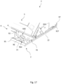
- the top frame coupling plate 96 is provided with coupling plate engagement means in the form of a hook element 964 comprising an arm 964a with a hook 964b and connected to a base section 961 of the top frame coupling plate 96 in a rotational joint 964c.
- Two engagement pins 962, 963 are provided on the base section 961 to interact with respective recesses 926b, 926a in the frame hinge base plate 921.
- the frame hinge base plate 921 is connected to a frame hinge side flange 924 connected to an inner side of the side frame member 22.
- a secondary hinge pin 927 is provided at the free end of the frame hinge side flange 924.
- the hinge assembly 9 provides for means to allow the sash 3 to be rotated about a substantially horizontal second hinge axis at a distance from the top frame member 21 and the top sash member 31.
- the sash hinge part 93 comprises a sash hinge base plate 931 connected to an outer side of the top sash member 31.
- the sash hinge base plate 931 is connected to a sash hinge side flange 934 connected to an inner side of the side sash member 32.
- the hook element 964 comprises a plurality of intermediate engagement portions configured to cooperate with a protrusion 926e on the frame hinge base plate 921 constituting the counterpart frame hinge part engagement means.
- the hook element 964 is biased towards its locking position in that a spring (not shown), received in a spring-receiving opening 964d in the arm 964a.
- a final engagement portion 964g is provided, in which the roof window 1 is in a fully assembled condition and ready for use.
- the first intermediate engagement portion 964h comprises an indentation larger than an indentation comprised in the second intermediate engagement portion 964i in the embodiment shown.
- the sash 3 is in this embodiment openable relative to the frame 2 within a predefined opening angle by means of operating assembly 5 connected to the sash 3 and the frame 2, here at the bottom sash and frame members.
- the operating assembly 5 comprises a manual operator in the form of a lever handle 58 and an electric operator 59, which may for instance be solar powered.
- the electric operator 59 is not shown in detail but may include a chain operator or a pantograph operator.
- the electric operator 59 is provided as auxiliary equipment. During daily use, either the lever handle 58 or the electric operator 59 is in use.
- connection between the manual operator 58 of the operating assembly 5 and the sash 3 and/or frame 2 is releasable and the connection between the electrical operator 59 and the sash 3 and/or frame 2 is releasable.
Landscapes
- Engineering & Computer Science (AREA)
- Architecture (AREA)
- Civil Engineering (AREA)
- Structural Engineering (AREA)
- Roof Covering Using Slabs Or Stiff Sheets (AREA)
Applications Claiming Priority (1)
| Application Number | Priority Date | Filing Date | Title |
|---|---|---|---|
| DKPA202370503 | 2023-10-02 |
Publications (1)
| Publication Number | Publication Date |
|---|---|
| EP4534774A1 true EP4534774A1 (de) | 2025-04-09 |
Family
ID=92973576
Family Applications (1)
| Application Number | Title | Priority Date | Filing Date |
|---|---|---|---|
| EP24204128.3A Pending EP4534774A1 (de) | 2023-10-02 | 2024-10-02 | Dachfenster mit einem rahmen mit einer dichtungsmuffe und einem dichtungselement sowie verfahren zur abdichtung einer verbindung zwischen einem dachfenster und einer dachstruktur |
Country Status (1)
| Country | Link |
|---|---|
| EP (1) | EP4534774A1 (de) |
Citations (5)
| Publication number | Priority date | Publication date | Assignee | Title |
|---|---|---|---|---|
| US5148643A (en) * | 1990-06-28 | 1992-09-22 | Wasco Products, Inc. | Skylight construction |
| US5575115A (en) * | 1991-12-06 | 1996-11-19 | V. Kann Rasmussen Industri A/S | Window with a frame of extruded profile members |
| GB2430943A (en) * | 2005-09-21 | 2007-04-11 | Viridian Concepts Ltd | Roof penetrating structure for incorporating into a roof |
| US10277161B2 (en) * | 2015-09-04 | 2019-04-30 | Viridian Concepts Ltd. | Photovoltaic roof covering |
| WO2023186246A1 (en) | 2022-03-31 | 2023-10-05 | Vkr Holding A/S | Roof window with a hinge assembly comprising a hinge unit and a coupling unit configured to assume at least one intermediate position and a final position |
-
2024
- 2024-10-02 EP EP24204128.3A patent/EP4534774A1/de active Pending
Patent Citations (5)
| Publication number | Priority date | Publication date | Assignee | Title |
|---|---|---|---|---|
| US5148643A (en) * | 1990-06-28 | 1992-09-22 | Wasco Products, Inc. | Skylight construction |
| US5575115A (en) * | 1991-12-06 | 1996-11-19 | V. Kann Rasmussen Industri A/S | Window with a frame of extruded profile members |
| GB2430943A (en) * | 2005-09-21 | 2007-04-11 | Viridian Concepts Ltd | Roof penetrating structure for incorporating into a roof |
| US10277161B2 (en) * | 2015-09-04 | 2019-04-30 | Viridian Concepts Ltd. | Photovoltaic roof covering |
| WO2023186246A1 (en) | 2022-03-31 | 2023-10-05 | Vkr Holding A/S | Roof window with a hinge assembly comprising a hinge unit and a coupling unit configured to assume at least one intermediate position and a final position |
Similar Documents
| Publication | Publication Date | Title |
|---|---|---|
| US5199234A (en) | Skylight assembly | |
| US9206612B2 (en) | Trim connection systems and methods | |
| US5150983A (en) | Corner lock | |
| US8096088B2 (en) | Glazing assembly for rough openings | |
| EP3002384B1 (de) | Dachfenster mit einer abdeckungsbefestigungsvorrichtung | |
| CZ196295A3 (en) | Set of composed profile systems made of metal and wood for door and window frames | |
| EA021992B1 (ru) | Окно, содержащее стеклопакет с краевым элементом | |
| EP3680417A1 (de) | Mittelabdeckungsanordnung und verfahren zum abdichten einer dachfensteranordnung | |
| EP4534774A1 (de) | Dachfenster mit einem rahmen mit einer dichtungsmuffe und einem dichtungselement sowie verfahren zur abdichtung einer verbindung zwischen einem dachfenster und einer dachstruktur | |
| EP3828359B1 (de) | Dachfensteranordnung mit mehreren flügelstrukturen und einem gemeinsamen rahmen und mit einer abdeckungsanordnung sowie verfahren zur herstellung einer solchen dachfensteranordnung | |
| JP3195254U (ja) | フレーム用のカバー手段を有する屋根窓 | |
| EP4466415A1 (de) | Dachfenster mit einem flügel mit profilelementen und verfahren zur herstellung eines dachfensters | |
| CN113802750A (zh) | 包括具有边界部分的安装型材的面板系统及适配该面板系统的方法 | |
| EP4534787A1 (de) | Dachfenster mit einem scharnier und einer betätigungsanordnung | |
| EP4534773A1 (de) | Dachfenster mit einem rahmen und einem flügel mit profilelementen | |
| CN118974366B (zh) | 包括具有接合单元的框架的屋顶窗户 | |
| JP4112775B2 (ja) | 上屋の構造 | |
| CN209990374U (zh) | 一种防风防水注胶角码及其连接结构 | |
| JP3190017B2 (ja) | 複合窓枠の無目構造 | |
| CN118946702B (zh) | 包括具有接纳结构的框架的屋顶窗户 | |
| CN214785206U (zh) | 一种密封垫圈和一种面板系统 | |
| CN213626242U (zh) | 一种面板系统 | |
| JP4397167B2 (ja) | 断熱ドア枠構造及び断熱ドア枠の組立方法 | |
| US12486669B2 (en) | Flashing device and a method of mounting a flashing device at a roof window | |
| CN118974365A (zh) | 包括具有中间元件的窗框的屋顶窗户 |
Legal Events
| Date | Code | Title | Description |
|---|---|---|---|
| PUAI | Public reference made under article 153(3) epc to a published international application that has entered the european phase |
Free format text: ORIGINAL CODE: 0009012 |
|
| STAA | Information on the status of an ep patent application or granted ep patent |
Free format text: STATUS: THE APPLICATION HAS BEEN PUBLISHED |
|
| AK | Designated contracting states |
Kind code of ref document: A1 Designated state(s): AL AT BE BG CH CY CZ DE DK EE ES FI FR GB GR HR HU IE IS IT LI LT LU LV MC ME MK MT NL NO PL PT RO RS SE SI SK SM TR |
|
| STAA | Information on the status of an ep patent application or granted ep patent |
Free format text: STATUS: REQUEST FOR EXAMINATION WAS MADE |
|
| 17P | Request for examination filed |
Effective date: 20251007 |