EP4534781A1 - Verriegelungsbeschlag-steuervorrichtung für tür- oder fensterrahmen - Google Patents
Verriegelungsbeschlag-steuervorrichtung für tür- oder fensterrahmen Download PDFInfo
- Publication number
- EP4534781A1 EP4534781A1 EP24203830.5A EP24203830A EP4534781A1 EP 4534781 A1 EP4534781 A1 EP 4534781A1 EP 24203830 A EP24203830 A EP 24203830A EP 4534781 A1 EP4534781 A1 EP 4534781A1
- Authority
- EP
- European Patent Office
- Prior art keywords
- housing
- control device
- hooking
- profile
- application face
- Prior art date
- Legal status (The legal status is an assumption and is not a legal conclusion. Google has not performed a legal analysis and makes no representation as to the accuracy of the status listed.)
- Pending
Links
Images


Classifications
-
- E—FIXED CONSTRUCTIONS
- E05—LOCKS; KEYS; WINDOW OR DOOR FITTINGS; SAFES
- E05B—LOCKS; ACCESSORIES THEREFOR; HANDCUFFS
- E05B9/00—Lock casings or latch-mechanism casings ; Fastening locks or fasteners or parts thereof to the wing
- E05B9/08—Fastening locks or fasteners or parts thereof, e.g. the casings of latch-bolt locks or cylinder locks to the wing
-
- E—FIXED CONSTRUCTIONS
- E05—LOCKS; KEYS; WINDOW OR DOOR FITTINGS; SAFES
- E05B—LOCKS; ACCESSORIES THEREFOR; HANDCUFFS
- E05B65/00—Locks or fastenings for special use
- E05B65/08—Locks or fastenings for special use for sliding wings
-
- E—FIXED CONSTRUCTIONS
- E05—LOCKS; KEYS; WINDOW OR DOOR FITTINGS; SAFES
- E05B—LOCKS; ACCESSORIES THEREFOR; HANDCUFFS
- E05B65/00—Locks or fastenings for special use
- E05B65/08—Locks or fastenings for special use for sliding wings
- E05B65/087—Locks or fastenings for special use for sliding wings the bolts sliding parallel to the wings
Definitions
- a locking fitting control device for application to sliding openings.
- This device comprises a housing in which a cup-shaped control handle is mounted so as to be able to move longitudinally in translation.
- This housing is designed to fit into a slot provided in the inner wall of a profile of the sliding opening.
- said housing also comprises a peripheral rim designed to be applied to the outer periphery of this slot in the profile. Fixing elements which are fitted at the ends transverse the housing in its part introduced into said light of the profile ensure, in combination with this peripheral edge and the action of fixing screws, a pinching effect on the thickness of the wall of the profile at the edges of this light to fix the control device in the latter.
- a control device for surface-mounted locking fitting again for a sliding opening, comprising, as previously, a housing designed to extend into an opening made in the wall, on the internal side of the dwelling, of a tubular sliding opening profile.
- This housing houses, in a sliding manner, a cup handle and comprises a peripheral support edge designed to come into contact with this internal side of the profile, on the periphery of said opening.
- this control device also comprises fixing members provided with means capable of extending under the peripheral edge of this opening so as to exert a tensile force on the housing having the consequence of applying the peripheral support edge of this housing to the internal side of the profile.
- One of these fixing members is in the form of a wedge mounted to move in translation at one of these ends of the housing, between a retracted position and a locking position in which this wedge is returned by a spring.
- this wedge is elastically retracted before returning to its locking position in which a rim forming a step engages under the internal edge of this opening, opposing the extraction of the housing from this opening and maintaining the peripheral support rim of this housing in application on the internal side of the profile.
- the other fixing member located at the opposite end of the housing, takes the form of a similar wedge except that it is fixed.
- This wedge also comprises, opposite the peripheral edge of the opening, 1 rim, forming a step which is engaged, at the time of assembly, on the edge of the opening, before inserting the opposite end of the housing into the latter by forcing the previously described fixing member to move back, by compression of the elastic return means.
- control device F according to the state of the art is illustrated, mounted on a profile P1 whose wall has a reduced thickness e1 compared to that e2 of the profile P2 visible in the Figure 2 and on which the same control device F is mounted.
- this differential thickness of the profile wall generates an offset D of the control device F in the opening O in which it is inserted.
- the magnitude of this offset depends on the angle ⁇ of the dihedral Di. However, an angle that is too open, generating a smaller offset, produces an anchor with less resistance compared to a more acute dihedral angle.
- the stepped edge defines a ramp facilitating the removal or tearing off of the control device from the profile.
- the present invention relates to a locking fitting control device for door or window type joinery, comprising a housing provided with a handle and comprising an application face intended to be applied to a joinery profile, this housing comprising at least two hooking members acting in opposition and designed to engage in an opening adapted in said joinery profile, these hooking members comprising hooking means and constituting, in combination with the application face of the housing, means for fixing the control device in said opening of the joinery profile.
- at least the hooking means of a fixing member are defined by a succession of at least two hooking edges adopting a stepped arrangement with respect to each other, each of these hooking edges extending essentially parallel under the application face of the housing at distinct distances with respect to this application face.
- the distance separating each of these hanging edges from the application face of the box corresponds to a given thickness of the wall of a joinery profile.
- the housing comprises a housing, essentially longitudinal, designed to extend into the opening of a profile, this housing being open totally or partially on the front face and accommodating a sliding handle, such as a cup handle, or other, the hooking member being in the form of an end wall of this housing, shaped like a staircase on one side.
- a gripping edge is able to generate a force resisting the housing from being pulled out from the profile to which it is fixed, acting essentially in a direction opposite to the force which generates it.
- each stair step corresponding to a hanging edge can be relatively low so that the offset produced by a profile wall of greater thickness in comparison with a profile wall of lesser thickness is particularly low.
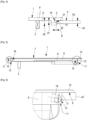
- the present invention relates to a control device 1 for locking hardware, such as a bolt, cremone bolt, cremone bolt lock or the like, for door or window type joinery.
- Such a control device 1 comprises a housing 5 which can take different embodiments, for example that of a cover plate of a rosette or other.
- this housing 5 comprises a housing 6, essentially longitudinal, totally or partially open on the front face 7 and accommodating, for example, a sliding handle 8 of the cup handle type or other.
- this housing 5 comprises an application face 9 intended to come into application on the external side 4 of the profile P1; P2.
- this application face 9 is defined by the lower face of a peripheral support rim 10 which, in this case, this housing 5 comprises.
- the latter also comprises at least two hooking members 11; 12 acting in opposite directions and designed to engage in an opening O adapted in the profile P1; P2 of the joinery.
- these hooking members 11; 12 constitute, in combination with the application face 9 of the housing 5, means for fixing the control device 1 in such an opening O of the profile P1; P2 of the joinery.
- Each of these attachment members 11; 12 comprises attachment means 13; 14. At least the attachment means 13 of one of these attachment members 11 are provided to be retractable, depending on the case, elastically or by means of a suitable control member.
- the hooking members 11; 12 are located at the longitudinal ends 15; 16 of the housing 5 and act in opposite directions relative to the median plane P of this housing 5 so as to cooperate with the edge or edge 17 of the opening O. More precisely, the hooking means 13; 14. engage under this edge 17 by sandwiching it with the application face 9 defined by the peripheral support rim 10.
- the hooking means 13 of the hooking member 11 are in the form of a point screw 18 on which an operator can act from the front face 7 of the housing 5 by means of a suitable tool to, depending on the case, screw this point screw 18 into a projecting position so that it can extend under the edge 17 of the opening O for the purpose of fixing the control device 1 on a profile P1; P2. Conversely, the operator can unscrew the point screw 18 if he wishes to dismantle the control device 1.
- this attachment member 11 can take many other forms of embodiment, in particular that of a wedge subjected to elastic return means in the blocking position, wedge comprising a rim forming a step intended to engage under the edge 17 of the opening O and, in collaboration with the application face 9, retain the control device 1 in this opening O.
- At least the hooking means 14 of a hooking member 12 are defined by a succession of at least two hooking edges 19, 20 adopting a staircase arrangement 21 relative to each other, each of these hooking edges 19, 20 extending essentially parallel under the application face 9 of the housing 5 at distances d1, d2 distinct from the latter.
- This staircase 21 is descending, relative to the application face 9, moving away from the median plane P of the housing 5.
- the further a step, corresponding to a hooking edge 19; 20 is distant d1; d2 from the application face 9, the further it is from this median plane P of the housing 5.
- the distances d1; d2 separating these attachment edges 19; 20 from the application face 9 correspond to thicknesses e1; e2 defined for walls 3 of profile P1; P2.
- the hooking member 14 may comprise a slot 22 open in the direction opposite to the median plane P of the housing 5, the upper wall 23 of which corresponds to the application face 9 of this housing 5 and the lower face 24 of which defines an acute angle ⁇ with this application face 9.
- a slot 22 is more particularly intended to accommodate and to enclose the edge 17 a wall 3 of profile of very small thickness.
- Such a configuration has the advantage of allowing the fixing of the control device 1 on metal profiles, particularly in aluminum, with a generally reduced wall thickness compared to profiles made of synthetic material, particularly PVC.
- the hooking member 14 can be in the form of an end wall 25 of the housing 6 defined by the casing 5 and extending into the opening O.
- This end wall 25, located at the end 16 of the casing 5, can be shaped like a staircase 21 on its side 26 opposite the edge 17 of the opening O.
- a control device intended to be fixed in an opening of a joinery profile does not necessarily have to be equipped with two hooking members acting in opposition, each of them being movable, in particular under the impulse of elastic return means, to guarantee the centering of the housing of this control device relative to the said opening in the profile.
- the solution according to the invention proves to be particularly economical while remedying the problem of excessive offset caused by known control devices depending on whether they are applied to profiles of greater or lesser thickness.
Landscapes
- Engineering & Computer Science (AREA)
- Mechanical Engineering (AREA)
- Wing Frames And Configurations (AREA)
Applications Claiming Priority (1)
| Application Number | Priority Date | Filing Date | Title |
|---|---|---|---|
| FR2310541A FR3153628B1 (fr) | 2023-10-03 | 2023-10-03 | Dispositif de commande de ferrure de verrouillage pour menuiserie de type porte ou fenêtre |
Publications (1)
| Publication Number | Publication Date |
|---|---|
| EP4534781A1 true EP4534781A1 (de) | 2025-04-09 |
Family
ID=88965306
Family Applications (1)
| Application Number | Title | Priority Date | Filing Date |
|---|---|---|---|
| EP24203830.5A Pending EP4534781A1 (de) | 2023-10-03 | 2024-10-01 | Verriegelungsbeschlag-steuervorrichtung für tür- oder fensterrahmen |
Country Status (2)
| Country | Link |
|---|---|
| EP (1) | EP4534781A1 (de) |
| FR (1) | FR3153628B1 (de) |
Citations (6)
| Publication number | Priority date | Publication date | Assignee | Title |
|---|---|---|---|---|
| US4676081A (en) * | 1985-08-12 | 1987-06-30 | Keycon Industries, Inc. | Snap-in semi-flush mounted panel lock |
| FR2761718A1 (fr) | 1997-04-03 | 1998-10-09 | Ferco Int Usine Ferrures | Ferrure de verrouillage pour ouvrant coulissant de porte, fenetre ou analogue |
| FR2761719A1 (fr) | 1997-04-03 | 1998-10-09 | Ferco Int Usine Ferrures | Ferrure de verrouillage pour ouvrant coulissant |
| FR2826995A1 (fr) * | 2001-07-05 | 2003-01-10 | Charles Prunet | Ferrure de verrouillage d'ouvrant coulissant a boitier technique et parement distincts et fixes sur l'ouvrant |
| FR2861788A1 (fr) | 2003-10-31 | 2005-05-06 | Ferco Int Usine Ferrures | Ferrure de verrouillage pour ouvrant coulissant |
| EP1709267B1 (de) * | 2004-01-26 | 2016-10-12 | Dieter Ramsauer | Klipsbefestigung für die schnellmontage von beschlageinrichtungen, wie schwenkhebelverschlüsse, scharnierteile in durchbrüchen in einer dünnen wand |
-
2023
- 2023-10-03 FR FR2310541A patent/FR3153628B1/fr active Active
-
2024
- 2024-10-01 EP EP24203830.5A patent/EP4534781A1/de active Pending
Patent Citations (6)
| Publication number | Priority date | Publication date | Assignee | Title |
|---|---|---|---|---|
| US4676081A (en) * | 1985-08-12 | 1987-06-30 | Keycon Industries, Inc. | Snap-in semi-flush mounted panel lock |
| FR2761718A1 (fr) | 1997-04-03 | 1998-10-09 | Ferco Int Usine Ferrures | Ferrure de verrouillage pour ouvrant coulissant de porte, fenetre ou analogue |
| FR2761719A1 (fr) | 1997-04-03 | 1998-10-09 | Ferco Int Usine Ferrures | Ferrure de verrouillage pour ouvrant coulissant |
| FR2826995A1 (fr) * | 2001-07-05 | 2003-01-10 | Charles Prunet | Ferrure de verrouillage d'ouvrant coulissant a boitier technique et parement distincts et fixes sur l'ouvrant |
| FR2861788A1 (fr) | 2003-10-31 | 2005-05-06 | Ferco Int Usine Ferrures | Ferrure de verrouillage pour ouvrant coulissant |
| EP1709267B1 (de) * | 2004-01-26 | 2016-10-12 | Dieter Ramsauer | Klipsbefestigung für die schnellmontage von beschlageinrichtungen, wie schwenkhebelverschlüsse, scharnierteile in durchbrüchen in einer dünnen wand |
Also Published As
| Publication number | Publication date |
|---|---|
| FR3153628A1 (fr) | 2025-04-04 |
| FR3153628B1 (fr) | 2025-08-29 |
Similar Documents
| Publication | Publication Date | Title |
|---|---|---|
| FR2747423A1 (fr) | Dispositif de roulement pour ouvrant coulissant de porte, fenetre ou analogue | |
| EP0952284B1 (de) | Verriegelungsvorrichtung für einen Schiebeflügel | |
| EP0757146A1 (de) | Verriegelungsvorrichtung mit mindestens einem Riegel für einen Gleitrahmen | |
| EP2650460A2 (de) | Vorrichtung zum provisorischen Verschließen eines Öffnungselements auf einem Rahmenelement | |
| EP4534781A1 (de) | Verriegelungsbeschlag-steuervorrichtung für tür- oder fensterrahmen | |
| EP0892133B1 (de) | Verriegelungsbeschlag für Schiebeflügel und Einbruchssicherung für einen solchen Beschlag | |
| EP1052357B1 (de) | Schliessblech | |
| EP1957733B1 (de) | Provisorische Verriegelungsvorrichtung | |
| BE1015014A4 (fr) | Ferrure de verrouillage d'ouvrant dotee pour sa fixation de moyens d'appui interieur et exterieur decales et ouvrant equipe d'une telle ferrure. | |
| EP1059409B1 (de) | Antriebsgetriebe für Schlossnuss | |
| FR2686646A1 (fr) | Penture reglable pour le ferrage notamment de portes ou de volets, cavalier d'assemblage et procede d'assemblage d'une telle penture. | |
| FR2893300A1 (fr) | Dispositif d'ecartement securise a l'arrachement | |
| WO2019171264A1 (fr) | Dispositif d'obturation d'une ouverture dans la paroi d'un batiment | |
| EP2909400B1 (de) | Bolzenbefestigungsvorrichtung für eine kraftfahrzeugtür und kraftfahrzeug mit solch einer befestigungsvorrichtung | |
| EP0997598B1 (de) | Schraubenführungsvorrichtung für Treibstange oder Treibstangenschloss | |
| FR2824861A1 (fr) | Ferrure de verrouillage pour ouvrant notamment coulissant | |
| EP2006155A1 (de) | Unverletzliche Befestigungsvorrichtung eines Bauteils in einer Aussparung einer Struktur | |
| FR2904354A1 (fr) | Ouvrant a capot | |
| FR3078734A1 (fr) | Kit pour le montage dans un ouvrant d’un boitier de serrure a pene de hauteur ajustable et ensemble comprenant un ouvrant et un tel kit, procede de fabrication et de montage d’un tel ensemble | |
| EP0937851A1 (de) | Zwischengeschaltete Sicherheitsvorrichtung für Drehtür oder Drehfenster | |
| FR2880051A1 (fr) | Element de ferrure de type gache pour feuillure de menuiserie | |
| EP1605119A1 (de) | Verriegelungsanordnung für Tür, Fenster oder verschiebbare Fenstertür | |
| EP4023830A1 (de) | Verriegelungssystem mit clip für bodenplatte | |
| EP0994225B1 (de) | Stangenaustrittsführung für Treibstangen oder Treibstangenschloss | |
| FR2970497A1 (fr) | Serrure multifonction pour ouvrant coulissant |
Legal Events
| Date | Code | Title | Description |
|---|---|---|---|
| PUAI | Public reference made under article 153(3) epc to a published international application that has entered the european phase |
Free format text: ORIGINAL CODE: 0009012 |
|
| STAA | Information on the status of an ep patent application or granted ep patent |
Free format text: STATUS: THE APPLICATION HAS BEEN PUBLISHED |
|
| AK | Designated contracting states |
Kind code of ref document: A1 Designated state(s): AL AT BE BG CH CY CZ DE DK EE ES FI FR GB GR HR HU IE IS IT LI LT LU LV MC ME MK MT NL NO PL PT RO RS SE SI SK SM TR |
|
| STAA | Information on the status of an ep patent application or granted ep patent |
Free format text: STATUS: REQUEST FOR EXAMINATION WAS MADE |
|
| 17P | Request for examination filed |
Effective date: 20250820 |
|
| RIC1 | Information provided on ipc code assigned before grant |
Ipc: E05B 9/08 20060101AFI20251107BHEP |
|
| GRAP | Despatch of communication of intention to grant a patent |
Free format text: ORIGINAL CODE: EPIDOSNIGR1 |
|
| STAA | Information on the status of an ep patent application or granted ep patent |
Free format text: STATUS: GRANT OF PATENT IS INTENDED |
|
| INTG | Intention to grant announced |
Effective date: 20260105 |
|
| P01 | Opt-out of the competence of the unified patent court (upc) registered |
Free format text: CASE NUMBER: UPC_APP_0018379_4534781/2025 Effective date: 20251218 |