EP4534794A1 - Composant de forage protégé contre l'usure et la corrosion à base de nickel - Google Patents
Composant de forage protégé contre l'usure et la corrosion à base de nickel Download PDFInfo
- Publication number
- EP4534794A1 EP4534794A1 EP23201590.9A EP23201590A EP4534794A1 EP 4534794 A1 EP4534794 A1 EP 4534794A1 EP 23201590 A EP23201590 A EP 23201590A EP 4534794 A1 EP4534794 A1 EP 4534794A1
- Authority
- EP
- European Patent Office
- Prior art keywords
- drill component
- corrosion protection
- drill
- protection layer
- component
- Prior art date
- Legal status (The legal status is an assumption and is not a legal conclusion. Google has not performed a legal analysis and makes no representation as to the accuracy of the status listed.)
- Withdrawn
Links
Images


Classifications
-
- E—FIXED CONSTRUCTIONS
- E21—EARTH OR ROCK DRILLING; MINING
- E21B—EARTH OR ROCK DRILLING; OBTAINING OIL, GAS, WATER, SOLUBLE OR MELTABLE MATERIALS OR A SLURRY OF MINERALS FROM WELLS
- E21B1/00—Percussion drilling
-
- C—CHEMISTRY; METALLURGY
- C23—COATING METALLIC MATERIAL; COATING MATERIAL WITH METALLIC MATERIAL; CHEMICAL SURFACE TREATMENT; DIFFUSION TREATMENT OF METALLIC MATERIAL; COATING BY VACUUM EVAPORATION, BY SPUTTERING, BY ION IMPLANTATION OR BY CHEMICAL VAPOUR DEPOSITION, IN GENERAL; INHIBITING CORROSION OF METALLIC MATERIAL OR INCRUSTATION IN GENERAL
- C23C—COATING METALLIC MATERIAL; COATING MATERIAL WITH METALLIC MATERIAL; SURFACE TREATMENT OF METALLIC MATERIAL BY DIFFUSION INTO THE SURFACE, BY CHEMICAL CONVERSION OR SUBSTITUTION; COATING BY VACUUM EVAPORATION, BY SPUTTERING, BY ION IMPLANTATION OR BY CHEMICAL VAPOUR DEPOSITION, IN GENERAL
- C23C18/00—Chemical coating by decomposition of either liquid compounds or solutions of the coating forming compounds, without leaving reaction products of surface material in the coating; Contact plating
- C23C18/16—Chemical coating by decomposition of either liquid compounds or solutions of the coating forming compounds, without leaving reaction products of surface material in the coating; Contact plating by reduction or substitution, e.g. electroless plating
- C23C18/1601—Process or apparatus
- C23C18/1633—Process of electroless plating
- C23C18/1689—After-treatment
- C23C18/1692—Heat-treatment
-
- E—FIXED CONSTRUCTIONS
- E21—EARTH OR ROCK DRILLING; MINING
- E21B—EARTH OR ROCK DRILLING; OBTAINING OIL, GAS, WATER, SOLUBLE OR MELTABLE MATERIALS OR A SLURRY OF MINERALS FROM WELLS
- E21B7/00—Special methods or apparatus for drilling
Definitions
- the present invention relates to a drill component, for example a rod, tube or coupling for percussive drilling having a corrosion and / or wear protection layer.
- Percussion drill bits are widely used both for drilling relatively shallow bores in hard rock and for creating deep boreholes.
- drill strings are typically used in which a plurality of rods or tubes are interconnected to advance the drill bit and increase the depth of the hole.
- a terrestrial machine is operative to transfer a combined impact and rotary drive motion to an upper end of the drill string whilst a drill bit positioned at the lower end is operative to crush the rock and form the boreholes.
- Acidic water is commonly used as a flushing media in percussive drilling which leads to corrosion of the drilling components, including the drill rods, tubes, and couplings. This can lead, for example, to issues with corrosion fatigue as the mechanical strength of the material is decreased. Consequently, the service life of the drill rod, tube or coupling is reduced.
- Known methods to add corrosion protection to drill components include adding a layer of phosphate which is then coated in wax. This method provides sufficient corrosion protection during transportation of the drill component but is insufficient to protect against corrosion during the drilling operation.
- the problem to be solved is how to improve the corrosion and / or wear resistance of drill components.
- This objective is achieved by providing a drill component having a longitudinal axis, extending axially between a first end at an axially forward end and a second end at an axially rearward end; an external surface; and an internal surface; wherein at least part of the external surface is coated with a first corrosion protection layer; wherein the first corrosion protection layer is nickel-based; and at least part of the first corrosion protection layer is coated with a polymer-based sealant top layer.
- the combination of the nickel-based corrosion protection layer with the polymer-based sealant top sealant results in fewer open cracks and flaws between the atmosphere and steel substrate and therefore improved resistance against corrosion is achieved.
- This coating combination provides a corrosion protective layer on the drill component thus delaying radial crack propagation and hence delaying transversal fractures.
- the inclusion of the coating increases the service life of the thread, especially in mines where there is acidic water present.
- the coating will also increase the wear resistance of the drill component.
- this coating can be applied in a relatively simple, inexpensive manner that does not pose any major health, safety, or environmental concerns.
- the internal surface of the drill component is coated with the first corrosion protection layer and / or the polymer-based sealant top layer.
- this provides protection against cavitation and resistance against corrosion on the inside of the drill component as well as the outside, therefore extending the lifetime of the drill component.
- the thickness of first corrosion protection layer is between 5 - 200 ⁇ m.
- this thickness provides the optimal balance between providing sufficient corrosion and wear protection without adding excessive costs.
- the thickness of the polymer-based sealant top layer is between 0.1 - 10 ⁇ m.
- this provides the optimal balance between having sufficient thickness to be effective whilst not adding unnecessary cost or adding the risk that streaks are formed as the coating dries.
- the polymer-based sealant top layer may also penetrate into the cracks therefore providing extra adhesion and corrosion protection.
- the phosphorus content of the nickel phosphorus alloy is 6-9 wt%.
- this phosphorus content provides increased wear without undesirable brittleness.
- the first corrosion protection layer and the polymer-based sealant top layer are located on all parts of the drill component.
- this provides highly comprehensive corrosion resistance.
- the first corrosion protection layer and the polymer-based sealant top layer are located only on selected parts of the drill component.
- this reduces costs.
- the drill component is a drill rod.
- the drill component is a drill tube.
- the drill component is a coupling.
- Another aspect of the present invention relates to a method for providing corrosion and / or wear protection on drill component as described hereinbefore or hereinafter comprising the steps of:
- this method provides a means to provide a highly effective corrosion resistance protection to the drill component, as well as providing a high wear resistant coating. This method does not pose any major health, safety, or environmental issues either.
- the first corrosion protection layer is applied using an electroless nickel bath.
- this method is quick and less harmful to the environment compared to alternative methods of providing corrosion resistant coatings.
- a further benefit of this method is that it can provide a coating having a more uniform thickness with high reproducibility.
- the polymer-based sealant top layer is sprayed on.
- this method provides a coating having a uniform thickness.
- the heat treatment is conducted at a temperature of between 150 - 300°C for 30 - 120 minutes.
- this temperature range provides the balance between having a high enough temperature and heating time that a hard and wear resistant surface is formed and not having too high a temperature and time that case hardened properties of the steel substrate are adversely affected.
- the drill component is shot peened or blasted before the nickel-based corrosion protection layer is applied.
- this step provides improved adhesion of the corrosion protection layer to the surface of the drill component.
- Figure 1 shows a drill component 2 for percussive drilling, comprising a hollow elongate main length section 4 having a longitudinal axis 10 extending axially between a first end 12 at an axially forward end 14 and a second end 16 at an axially rearward end 22 of the drill component 2.
- the first end 12 could comprise a male connecting component 24 or a female connecting component 30.
- the second end 16 could comprise a male connecting component 24 or a female connecting component 30.
- the drill component 2 may contain one male connecting component 24 and one female connecting component 30 or two males connecting components 24 or two female connecting components 30.
- the drill component 2 has an external surface 6 and an internal surface 8.
- the drill component 2 could for example be a bottom contact MF rod, as shown in figure 1 , wherein the first end 12 comprises a male connecting component 24 and the second end 16 comprises a female connecting component 30.
- Figure 2 shows that optionally the drill component 2 may comprise a radially projecting shoulder 26 that axially separates the main length section 4 and the male connecting means 24.
- the shoulder 26 comprises a peripheral surface 28 that has a greater outer diameter than the outer diameter of the main length section 4.
- Figure 2 shows a shoulder contact MF rod.
- Figure 3 shows that alternatively the drill component 2 could for example be a tube comprising one male connecting component 24 and one female connecting component 30.
- the tube may also comprise a shoulder.
- Figure 4 shows that alternatively the drill component 2 could for example be a drifter rod having two male connecting components 24.
- Figure 5 shows that alternatively the drill component 2 could for example be a hexagonal rod.
- FIGS 1-5 all show examples where the male connecting components 24 and the female connecting components 30 are threaded.
- Figure 6 shows that alternatively the drill component 2 could have connecting components that are conical and therefore form a taper fit connection.
- the taper fit connection could be employed on any other rod or tube geometry.
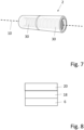
- Figure 7 show that alternatively the drill component 2 is a coupling.
- This invention could also apply to any other type of drill rod, tube or coupling with any combination of geometry and connection form.
- Figure 8 shows that at least a part of the external surface 6 of the drill component 2 is coated with a first corrosion protection layer 18 wherein the first corrosion protection layer 18 is nickel-based. At least part of the first corrosion protection layer 18 is coated with a polymer-based sealant top layer 20. Areas of the external surface 6 of the drill component 2 that are not coated with the first corrosion protection layer 18 may also be coated with the polymer-based sealant top layer 20. Part or all of the first corrosion protection layer 18 could be coated with the polymer-based sealant top layer 20.
- Nickel-based means that the major component on the first corrosion protection layer 18, in both mass % and atomic %, is nickel, for example >50% nickel, for example >70% nickel, for example >80% nickel, for example >90% nickel.
- Polymer-based means that the major component of the sealant top layer 20, in both mass % and atomic %, is polymer, for example >50% polymer, for example >70% polymer, for example >80% polymer, for example >90% polymer.
- At least part of the internal surface 8 of the drill component 2 may also be coated with the first corrosion protection layer 18 and / or the polymer-based sealant top layer 20. At least part or all of the internal surface 8 may be coated with only first corrosion protection layer 18. At least part or all of the internal surface 8 may be coated with only the polymer-based sealant top layer 20. At least part or all of the internal surface 8 may be coated with both the first corrosion protection layer 18 and the polymer-based sealant top layer 20. Any combination of these options is possible.
- first corrosion protection layer 18 is between 5-200 ⁇ m, more preferably between 7-100 ⁇ m, even more preferably between 10-50 ⁇ m.
- the thickness of the polymer-based sealant top layer 20 is between 0.1 - 10 ⁇ m, preferably between 0.1 - 5 ⁇ m.
- the first corrosion protection layer 18 could be nickel alloyed with sulphur, phosphorus, boron, or any other suitable element.
- the first corrosion protection layer 18 is a nickel phosphorous alloy.
- the phosphorus content of the nickel phosphorus alloy is 6-9 wt%.
- the polymer could be a Teflon or a fluorinated polymer (e.g., Polytetrafluoroethylene (PTFE)) or a non-fluorinated crystalline polymer (e.g., Polyether ether ketone (PEEK)) or a high-density polymer (e.g., Ultra-high-molecular-weight polyethylene (UHMWPE)).
- PTFE Polytetrafluoroethylene
- PEEK Polyether ether ketone
- UHMWPE Ultra-high-molecular-weight polyethylene
- the external surface 6 includes the external surfaces of the main length section 4, the male connecting components 24 and the female connecting components 30.
- the internal surface 8 includes the internal surfaces of main length section 4, the male connecting components 24 and the female connecting components 30.
- External surfaces are considered to be any area on the outside of the drill component 2.
- Internal surfaces are considered to be any area on the inside of the drill component 2.
- the present application further relates to a method for providing corrosion protection on a drill component 2 comprising the steps of:
- the first corrosion protection layer 18 is applied using an electroless nickel bath.
- the nickel or nickel-based alloy adheres to the substrate, the substrate being the metal of the drill component.
- electroless nickel plating the object reacts to the plating bath chemistry, creating a uniform and smooth, layer with very little surface porosity. The even deposition makes it an ideal choice for complex, non-line of sight, geometries and often eliminates the need for grinding after plating.
- the first corrosion protection layer could be applied via electroplating or any other suitable method.
- the polymer-based sealant top layer 20 is sprayed on.
- the polymer-based sealant top layer 20 could be applied through dipping or any other suitable method.
- the purpose of the heating step is to enable the formation of Ni-P intermetallic phases, improve the adhesion to the substrate and to cure the polymer-based sealant top layer.
- the heat treatment is conducted in furnace.
- the heat treatment is conducted at a temperature of between 150 - 300°C, preferably between 225 - 260°C. In one embodiment the heat treatment is conducted for between 30 - 120 minutes, preferably between 45 - 75 minutes.
- the same method can be used to apply the first corrosion protection layer 18 and / or the polymer-based sealant top layer 20 to the internal surface 8 of the drill component 2.
- the surface of the drill component 2 is shot peened or blasted before the nickel-based corrosion protection layer 18 is applied.
- the drill component as described hereinbefore or hereinafter could be part of a drill string and / or a drill rig arrangement.
Landscapes
- Engineering & Computer Science (AREA)
- Geology (AREA)
- Life Sciences & Earth Sciences (AREA)
- Chemical & Material Sciences (AREA)
- Mining & Mineral Resources (AREA)
- Geochemistry & Mineralogy (AREA)
- Fluid Mechanics (AREA)
- General Life Sciences & Earth Sciences (AREA)
- Physics & Mathematics (AREA)
- Environmental & Geological Engineering (AREA)
- Mechanical Engineering (AREA)
- General Chemical & Material Sciences (AREA)
- Chemical Kinetics & Catalysis (AREA)
- Materials Engineering (AREA)
- Metallurgy (AREA)
- Organic Chemistry (AREA)
- Earth Drilling (AREA)
Priority Applications (2)
| Application Number | Priority Date | Filing Date | Title |
|---|---|---|---|
| EP23201590.9A EP4534794A1 (fr) | 2023-10-04 | 2023-10-04 | Composant de forage protégé contre l'usure et la corrosion à base de nickel |
| PCT/EP2024/077834 WO2025073829A1 (fr) | 2023-10-04 | 2024-10-03 | Composant de forage protégé contre l'usure et la corrosion, à base de nickel |
Applications Claiming Priority (1)
| Application Number | Priority Date | Filing Date | Title |
|---|---|---|---|
| EP23201590.9A EP4534794A1 (fr) | 2023-10-04 | 2023-10-04 | Composant de forage protégé contre l'usure et la corrosion à base de nickel |
Publications (1)
| Publication Number | Publication Date |
|---|---|
| EP4534794A1 true EP4534794A1 (fr) | 2025-04-09 |
Family
ID=88287208
Family Applications (1)
| Application Number | Title | Priority Date | Filing Date |
|---|---|---|---|
| EP23201590.9A Withdrawn EP4534794A1 (fr) | 2023-10-04 | 2023-10-04 | Composant de forage protégé contre l'usure et la corrosion à base de nickel |
Country Status (2)
| Country | Link |
|---|---|
| EP (1) | EP4534794A1 (fr) |
| WO (1) | WO2025073829A1 (fr) |
Citations (3)
| Publication number | Priority date | Publication date | Assignee | Title |
|---|---|---|---|---|
| US20160208562A1 (en) * | 2013-10-02 | 2016-07-21 | Vallourec Oil And Gas France | Connecting element for a tubular component overlaid with a metallic composite deposit and method of obtaining such element |
| US20200407852A1 (en) * | 2019-06-28 | 2020-12-31 | Schlumberger Technology Corporation | Anti-Scale Deposition Hierarchical Coatings for Wellbore Applications |
| US20220259742A1 (en) * | 2019-07-26 | 2022-08-18 | Eni S.P.A. | Multilayered nickel-phosphorus composite |
-
2023
- 2023-10-04 EP EP23201590.9A patent/EP4534794A1/fr not_active Withdrawn
-
2024
- 2024-10-03 WO PCT/EP2024/077834 patent/WO2025073829A1/fr active Pending
Patent Citations (3)
| Publication number | Priority date | Publication date | Assignee | Title |
|---|---|---|---|---|
| US20160208562A1 (en) * | 2013-10-02 | 2016-07-21 | Vallourec Oil And Gas France | Connecting element for a tubular component overlaid with a metallic composite deposit and method of obtaining such element |
| US20200407852A1 (en) * | 2019-06-28 | 2020-12-31 | Schlumberger Technology Corporation | Anti-Scale Deposition Hierarchical Coatings for Wellbore Applications |
| US20220259742A1 (en) * | 2019-07-26 | 2022-08-18 | Eni S.P.A. | Multilayered nickel-phosphorus composite |
Also Published As
| Publication number | Publication date |
|---|---|
| WO2025073829A1 (fr) | 2025-04-10 |
Similar Documents
| Publication | Publication Date | Title |
|---|---|---|
| CN1126894C (zh) | 重型钻管件及其生产方法 | |
| NO20024152L (no) | Gjengeforbindelse og fjellborelement | |
| EP4206511B1 (fr) | Tuyau métallique pour puits de pétrole | |
| PL199832B1 (pl) | Połączenie gwintowe rur stalowych | |
| NO20024151L (no) | Gjengeforbindelse og bergborelement | |
| EP4534794A1 (fr) | Composant de forage protégé contre l'usure et la corrosion à base de nickel | |
| RU2334156C1 (ru) | Бурильная труба с соединительными замками | |
| Radtke | New high strength and faster drilling TSP diamond cutters | |
| EP4553270A1 (fr) | Protection contre l'usure à base de nickel pour un ensemble de forage dth | |
| EP4526545B1 (fr) | Adaptateur de tige protégé contre l'usure et la corrosion à base de nickel | |
| US20110223443A1 (en) | Metallic components for use in corrosive environments and method of manufacturing | |
| WO2023275239A1 (fr) | Adaptateur de queue de forêt revétue par laser | |
| OA21851A (en) | Nickel Based Wear And Corrosion Protected Shank Adapter. | |
| RU68090U1 (ru) | Бурильная труба с соединительными замками | |
| EP4279705A1 (fr) | Adaptateur de tige à double couche de protection contre l'usure et la corrosion | |
| US20240301538A1 (en) | Wear resistant thermal spray alloy | |
| OA21495A (en) | Metal pipe for oil well. | |
| CN120758873A (zh) | 一种耐磨损耐腐蚀钻杆内涂层涂料及其制备方法 | |
| Wells | Workstring Tubing: The New Drill Pipe (And How to Protect It) | |
| JP6569355B2 (ja) | 坑井の掘削方法、その掘削方法に用いられるドリルパイプ及びツールジョイント | |
| JP6672911B2 (ja) | 坑井の掘削方法、その掘削方法に用いられるドリルパイプ及びツールジョイント | |
| WO2024003240A1 (fr) | Tubes ou tiges revêtus par laser pour forage par percussion | |
| Makarenko et al. | Corrosion and Mechanical Tests on Drilling Column Tubes and Clamps. |
Legal Events
| Date | Code | Title | Description |
|---|---|---|---|
| PUAI | Public reference made under article 153(3) epc to a published international application that has entered the european phase |
Free format text: ORIGINAL CODE: 0009012 |
|
| STAA | Information on the status of an ep patent application or granted ep patent |
Free format text: STATUS: THE APPLICATION HAS BEEN PUBLISHED |
|
| AK | Designated contracting states |
Kind code of ref document: A1 Designated state(s): AL AT BE BG CH CY CZ DE DK EE ES FI FR GB GR HR HU IE IS IT LI LT LU LV MC ME MK MT NL NO PL PT RO RS SE SI SK SM TR |
|
| STAA | Information on the status of an ep patent application or granted ep patent |
Free format text: STATUS: THE APPLICATION HAS BEEN WITHDRAWN |
|
| 18W | Application withdrawn |
Effective date: 20251001 |