EP4534802A1 - Aube, moteur à turbine à gaz et procédé pour fabriquer une aube - Google Patents
Aube, moteur à turbine à gaz et procédé pour fabriquer une aube Download PDFInfo
- Publication number
- EP4534802A1 EP4534802A1 EP24204354.5A EP24204354A EP4534802A1 EP 4534802 A1 EP4534802 A1 EP 4534802A1 EP 24204354 A EP24204354 A EP 24204354A EP 4534802 A1 EP4534802 A1 EP 4534802A1
- Authority
- EP
- European Patent Office
- Prior art keywords
- airfoil
- section
- fiber plies
- sections
- radially
- Prior art date
- Legal status (The legal status is an assumption and is not a legal conclusion. Google has not performed a legal analysis and makes no representation as to the accuracy of the status listed.)
- Pending
Links
Images


Classifications
-
- F—MECHANICAL ENGINEERING; LIGHTING; HEATING; WEAPONS; BLASTING
- F01—MACHINES OR ENGINES IN GENERAL; ENGINE PLANTS IN GENERAL; STEAM ENGINES
- F01D—NON-POSITIVE DISPLACEMENT MACHINES OR ENGINES, e.g. STEAM TURBINES
- F01D5/00—Blades; Blade-carrying members; Heating, heat-insulating, cooling or antivibration means on the blades or the members
- F01D5/12—Blades
- F01D5/28—Selecting particular materials; Particular measures relating thereto; Measures against erosion or corrosion
- F01D5/282—Selecting composite materials, e.g. blades with reinforcing filaments
-
- F—MECHANICAL ENGINEERING; LIGHTING; HEATING; WEAPONS; BLASTING
- F01—MACHINES OR ENGINES IN GENERAL; ENGINE PLANTS IN GENERAL; STEAM ENGINES
- F01D—NON-POSITIVE DISPLACEMENT MACHINES OR ENGINES, e.g. STEAM TURBINES
- F01D5/00—Blades; Blade-carrying members; Heating, heat-insulating, cooling or antivibration means on the blades or the members
- F01D5/02—Blade-carrying members, e.g. rotors
-
- C—CHEMISTRY; METALLURGY
- C04—CEMENTS; CONCRETE; ARTIFICIAL STONE; CERAMICS; REFRACTORIES
- C04B—LIME, MAGNESIA; SLAG; CEMENTS; COMPOSITIONS THEREOF, e.g. MORTARS, CONCRETE OR LIKE BUILDING MATERIALS; ARTIFICIAL STONE; CERAMICS; REFRACTORIES; TREATMENT OF NATURAL STONE
- C04B35/00—Shaped ceramic products characterised by their composition; Ceramics compositions; Processing powders of inorganic compounds preparatory to the manufacturing of ceramic products
- C04B35/515—Shaped ceramic products characterised by their composition; Ceramics compositions; Processing powders of inorganic compounds preparatory to the manufacturing of ceramic products based on non-oxide ceramics
- C04B35/56—Shaped ceramic products characterised by their composition; Ceramics compositions; Processing powders of inorganic compounds preparatory to the manufacturing of ceramic products based on non-oxide ceramics based on carbides or oxycarbides
- C04B35/565—Shaped ceramic products characterised by their composition; Ceramics compositions; Processing powders of inorganic compounds preparatory to the manufacturing of ceramic products based on non-oxide ceramics based on carbides or oxycarbides based on silicon carbide
-
- C—CHEMISTRY; METALLURGY
- C04—CEMENTS; CONCRETE; ARTIFICIAL STONE; CERAMICS; REFRACTORIES
- C04B—LIME, MAGNESIA; SLAG; CEMENTS; COMPOSITIONS THEREOF, e.g. MORTARS, CONCRETE OR LIKE BUILDING MATERIALS; ARTIFICIAL STONE; CERAMICS; REFRACTORIES; TREATMENT OF NATURAL STONE
- C04B35/00—Shaped ceramic products characterised by their composition; Ceramics compositions; Processing powders of inorganic compounds preparatory to the manufacturing of ceramic products
- C04B35/71—Ceramic products containing macroscopic reinforcing agents
- C04B35/78—Ceramic products containing macroscopic reinforcing agents containing non-metallic materials
- C04B35/80—Fibres, filaments, whiskers, platelets, or the like
-
- F—MECHANICAL ENGINEERING; LIGHTING; HEATING; WEAPONS; BLASTING
- F01—MACHINES OR ENGINES IN GENERAL; ENGINE PLANTS IN GENERAL; STEAM ENGINES
- F01D—NON-POSITIVE DISPLACEMENT MACHINES OR ENGINES, e.g. STEAM TURBINES
- F01D5/00—Blades; Blade-carrying members; Heating, heat-insulating, cooling or antivibration means on the blades or the members
- F01D5/12—Blades
- F01D5/14—Form or construction
- F01D5/18—Hollow blades, i.e. blades with cooling or heating channels or cavities; Heating, heat-insulating or cooling means on blades
- F01D5/187—Convection cooling
-
- F—MECHANICAL ENGINEERING; LIGHTING; HEATING; WEAPONS; BLASTING
- F01—MACHINES OR ENGINES IN GENERAL; ENGINE PLANTS IN GENERAL; STEAM ENGINES
- F01D—NON-POSITIVE DISPLACEMENT MACHINES OR ENGINES, e.g. STEAM TURBINES
- F01D5/00—Blades; Blade-carrying members; Heating, heat-insulating, cooling or antivibration means on the blades or the members
- F01D5/12—Blades
- F01D5/28—Selecting particular materials; Particular measures relating thereto; Measures against erosion or corrosion
- F01D5/284—Selection of ceramic materials
-
- F—MECHANICAL ENGINEERING; LIGHTING; HEATING; WEAPONS; BLASTING
- F01—MACHINES OR ENGINES IN GENERAL; ENGINE PLANTS IN GENERAL; STEAM ENGINES
- F01D—NON-POSITIVE DISPLACEMENT MACHINES OR ENGINES, e.g. STEAM TURBINES
- F01D9/00—Stators
- F01D9/06—Fluid supply conduits to nozzles or the like
- F01D9/065—Fluid supply or removal conduits traversing the working fluid flow, e.g. for lubrication-, cooling-, or sealing fluids
-
- C—CHEMISTRY; METALLURGY
- C04—CEMENTS; CONCRETE; ARTIFICIAL STONE; CERAMICS; REFRACTORIES
- C04B—LIME, MAGNESIA; SLAG; CEMENTS; COMPOSITIONS THEREOF, e.g. MORTARS, CONCRETE OR LIKE BUILDING MATERIALS; ARTIFICIAL STONE; CERAMICS; REFRACTORIES; TREATMENT OF NATURAL STONE
- C04B2235/00—Aspects relating to ceramic starting mixtures or sintered ceramic products
- C04B2235/02—Composition of constituents of the starting material or of secondary phases of the final product
- C04B2235/50—Constituents or additives of the starting mixture chosen for their shape or used because of their shape or their physical appearance
- C04B2235/52—Constituents or additives characterised by their shapes
- C04B2235/5208—Fibers
- C04B2235/5216—Inorganic
- C04B2235/524—Non-oxidic, e.g. borides, carbides, silicides or nitrides
- C04B2235/5244—Silicon carbide
-
- C—CHEMISTRY; METALLURGY
- C04—CEMENTS; CONCRETE; ARTIFICIAL STONE; CERAMICS; REFRACTORIES
- C04B—LIME, MAGNESIA; SLAG; CEMENTS; COMPOSITIONS THEREOF, e.g. MORTARS, CONCRETE OR LIKE BUILDING MATERIALS; ARTIFICIAL STONE; CERAMICS; REFRACTORIES; TREATMENT OF NATURAL STONE
- C04B2235/00—Aspects relating to ceramic starting mixtures or sintered ceramic products
- C04B2235/02—Composition of constituents of the starting material or of secondary phases of the final product
- C04B2235/50—Constituents or additives of the starting mixture chosen for their shape or used because of their shape or their physical appearance
- C04B2235/52—Constituents or additives characterised by their shapes
- C04B2235/5208—Fibers
- C04B2235/5252—Fibers having a specific pre-form
-
- C—CHEMISTRY; METALLURGY
- C04—CEMENTS; CONCRETE; ARTIFICIAL STONE; CERAMICS; REFRACTORIES
- C04B—LIME, MAGNESIA; SLAG; CEMENTS; COMPOSITIONS THEREOF, e.g. MORTARS, CONCRETE OR LIKE BUILDING MATERIALS; ARTIFICIAL STONE; CERAMICS; REFRACTORIES; TREATMENT OF NATURAL STONE
- C04B2235/00—Aspects relating to ceramic starting mixtures or sintered ceramic products
- C04B2235/60—Aspects relating to the preparation, properties or mechanical treatment of green bodies or pre-forms
- C04B2235/614—Gas infiltration of green bodies or pre-forms
-
- C—CHEMISTRY; METALLURGY
- C04—CEMENTS; CONCRETE; ARTIFICIAL STONE; CERAMICS; REFRACTORIES
- C04B—LIME, MAGNESIA; SLAG; CEMENTS; COMPOSITIONS THEREOF, e.g. MORTARS, CONCRETE OR LIKE BUILDING MATERIALS; ARTIFICIAL STONE; CERAMICS; REFRACTORIES; TREATMENT OF NATURAL STONE
- C04B2235/00—Aspects relating to ceramic starting mixtures or sintered ceramic products
- C04B2235/60—Aspects relating to the preparation, properties or mechanical treatment of green bodies or pre-forms
- C04B2235/616—Liquid infiltration of green bodies or pre-forms
-
- C—CHEMISTRY; METALLURGY
- C04—CEMENTS; CONCRETE; ARTIFICIAL STONE; CERAMICS; REFRACTORIES
- C04B—LIME, MAGNESIA; SLAG; CEMENTS; COMPOSITIONS THEREOF, e.g. MORTARS, CONCRETE OR LIKE BUILDING MATERIALS; ARTIFICIAL STONE; CERAMICS; REFRACTORIES; TREATMENT OF NATURAL STONE
- C04B2235/00—Aspects relating to ceramic starting mixtures or sintered ceramic products
- C04B2235/70—Aspects relating to sintered or melt-casted ceramic products
- C04B2235/94—Products characterised by their shape
-
- F—MECHANICAL ENGINEERING; LIGHTING; HEATING; WEAPONS; BLASTING
- F05—INDEXING SCHEMES RELATING TO ENGINES OR PUMPS IN VARIOUS SUBCLASSES OF CLASSES F01-F04
- F05D—INDEXING SCHEME FOR ASPECTS RELATING TO NON-POSITIVE-DISPLACEMENT MACHINES OR ENGINES, GAS-TURBINES OR JET-PROPULSION PLANTS
- F05D2240/00—Components
- F05D2240/10—Stators
- F05D2240/12—Fluid guiding means, e.g. vanes
- F05D2240/122—Fluid guiding means, e.g. vanes related to the trailing edge of a stator vane
-
- F—MECHANICAL ENGINEERING; LIGHTING; HEATING; WEAPONS; BLASTING
- F05—INDEXING SCHEMES RELATING TO ENGINES OR PUMPS IN VARIOUS SUBCLASSES OF CLASSES F01-F04
- F05D—INDEXING SCHEME FOR ASPECTS RELATING TO NON-POSITIVE-DISPLACEMENT MACHINES OR ENGINES, GAS-TURBINES OR JET-PROPULSION PLANTS
- F05D2240/00—Components
- F05D2240/20—Rotors
- F05D2240/30—Characteristics of rotor blades, i.e. of any element transforming dynamic fluid energy to or from rotational energy and being attached to a rotor
- F05D2240/304—Characteristics of rotor blades, i.e. of any element transforming dynamic fluid energy to or from rotational energy and being attached to a rotor related to the trailing edge of a rotor blade
-
- F—MECHANICAL ENGINEERING; LIGHTING; HEATING; WEAPONS; BLASTING
- F05—INDEXING SCHEMES RELATING TO ENGINES OR PUMPS IN VARIOUS SUBCLASSES OF CLASSES F01-F04
- F05D—INDEXING SCHEME FOR ASPECTS RELATING TO NON-POSITIVE-DISPLACEMENT MACHINES OR ENGINES, GAS-TURBINES OR JET-PROPULSION PLANTS
- F05D2260/00—Function
- F05D2260/20—Heat transfer, e.g. cooling
- F05D2260/204—Heat transfer, e.g. cooling by the use of microcircuits
-
- F—MECHANICAL ENGINEERING; LIGHTING; HEATING; WEAPONS; BLASTING
- F05—INDEXING SCHEMES RELATING TO ENGINES OR PUMPS IN VARIOUS SUBCLASSES OF CLASSES F01-F04
- F05D—INDEXING SCHEME FOR ASPECTS RELATING TO NON-POSITIVE-DISPLACEMENT MACHINES OR ENGINES, GAS-TURBINES OR JET-PROPULSION PLANTS
- F05D2300/00—Materials; Properties thereof
- F05D2300/60—Properties or characteristics given to material by treatment or manufacturing
- F05D2300/603—Composites; e.g. fibre-reinforced
- F05D2300/6033—Ceramic matrix composites [CMC]
-
- Y—GENERAL TAGGING OF NEW TECHNOLOGICAL DEVELOPMENTS; GENERAL TAGGING OF CROSS-SECTIONAL TECHNOLOGIES SPANNING OVER SEVERAL SECTIONS OF THE IPC; TECHNICAL SUBJECTS COVERED BY FORMER USPC CROSS-REFERENCE ART COLLECTIONS [XRACs] AND DIGESTS
- Y02—TECHNOLOGIES OR APPLICATIONS FOR MITIGATION OR ADAPTATION AGAINST CLIMATE CHANGE
- Y02T—CLIMATE CHANGE MITIGATION TECHNOLOGIES RELATED TO TRANSPORTATION
- Y02T50/00—Aeronautics or air transport
- Y02T50/60—Efficient propulsion technologies, e.g. for aircraft
Definitions
- Airfoils in the turbine section are typically formed of a superalloy and may include thermal barrier coatings to extend temperature capability and lifetime. Ceramic matrix composite (“CMC”) materials are also being considered for airfoils. Among other attractive properties, CMCs have high temperature resistance. Despite this attribute, however, there are unique challenges to implementing CMCs in airfoils.
- the intermediate passage sections are radially curved.
- the radial tube has a radiused end in the trailing edge region, and the at least one inlet orifice section opens to the internal cavity at a location forward of the radiused end.
- intermediate passage section are formed, wherein the intermediate passage sections partially overlap with the preformed slots to provide a radially-elongated multi-dimensional plenum.
- At least one inlet orifice section is formed through the core preform to the internal cavity to provide a second intermediate preform, and one or more additional skin fiber plies are laid-up around the second intermediate preform to form a final preform.
- the final preform is then densified with additional ceramic matrix material, and a plurality of outlet orifice sections are formed that extend through the trailing edge.
- the at least one inlet orifice section, the a radially-elongated multi-dimensional plenum, the intermediate passage sections, and the plurality of outlet orifice sections are connected to provide at least one cooling passage.
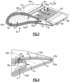
- FIG. 1 schematically illustrates a gas turbine engine 20.
- the gas turbine engine 20 is disclosed herein as a two-spool turbofan that generally incorporates a fan section 22, a compressor section 24, a combustor section 26 and a turbine section 28.
- the fan section 22 drives air along a bypass flow path B in a bypass duct defined within a housing 15 such as a fan case or nacelle, and also drives air along a core flow path C for compression and communication into the combustor section 26 then expansion through the turbine section 28.
- the exemplary engine 20 generally includes a low speed spool 30 and a high speed spool 32 mounted for rotation about an engine central longitudinal axis A relative to an engine static structure 36 via several bearing systems 38. It should be understood that various bearing systems 38 at various locations may alternatively or additionally be provided, and the location of bearing systems 38 may be varied as appropriate to the application.
- the engine 20 bypass ratio is greater than about ten (10:1)
- the fan diameter is significantly larger than that of the low pressure compressor 44
- the low pressure turbine 46 has a pressure ratio that is greater than about five (5:1).
- Low pressure turbine 46 pressure ratio is pressure measured prior to an inlet of low pressure turbine 46 as related to the pressure at the outlet of the low pressure turbine 46 prior to an exhaust nozzle.
- the geared architecture 48 may be an epicycle gear train, such as a planetary gear system or other gear system, with a gear reduction ratio of greater than about 2.3:1 and less than about 5:1. It should be understood, however, that the above parameters are only exemplary of one embodiment of a geared architecture engine and that the present invention is applicable to other gas turbine engines including direct drive turbofans.
- the fan section 22 of the engine 20 is designed for a particular flight condition -- typically cruise at about 0.8 Mach and about 35,000 feet (10,668 meters).
- the flight condition of 0.8 Mach and 35,000 ft (10,668 meters), with the engine at its best fuel consumption - also known as "bucket cruise Thrust Specific Fuel Consumption ('TSFC')" - is the industry standard parameter of lbm of fuel being burned divided by lbf of thrust the engine produces at that minimum point.
- 'TSFC' Thrust Specific Fuel Consumption
- “Low fan pressure ratio” is the pressure ratio across the fan blade alone, without a Fan Exit Guide Vane (“FEGV”) system.
- the fiber plies 66 include core fiber plies 68 and skin fiber plies 70.
- the core fiber plies 68 define a radial tube 72 that circumscribes and immediately borders the internal cavity 61.
- the skin fiber plies 70 define the exterior profile of the airfoil section 60 and wrap around the core fiber plies 68 from the pressure side 60d in the trailing edge region 63, through the leading edge 60a, and to the suction side 60c in the trailing edge region 63.
- a filler element 76 in the trailing edge region 63, aft of the internal cavity 61.
- a filler element in general is often colloquially referred to as a "noodle" and serves as a non-structural space-filler, usually in an interstice where other fiber plies bend.
- the filler element 76 fills in the region aft of the radiused end 74 and is sandwiched between the skin fiber plies 70 on the pressure side 60d and the skin fiber plies 70 on the suction side 60c.
- the filler element 76 may be formed of, but is not limited to, a bundle of densified ceramic fibers (a CMC) or a monolithic ceramic.
- the airfoil section 60 includes at least one cooling passage 78, with inlet 78a ( Figure 2B ), for a flow of cooling air.
- Figure 3 illustrates a cutaway view showing portions of the cooling passage 78.
- the cooling air is bleed air from the compressor section 24 that is provided into the internal cavity 61 and flows from the internal cavity 61 into the cooling passage(s) 78.
- Figures 4 and 5 show sectioned views through portions of the cooling passage 78
- Figure 6 illustrates an isolated view of the cooling passage 78 as a solid volume.
- the inlet section 78a of the passage 78 is at a location L that is axially forward of the radiused end 74, so as to circumvent the end 74 and thus avoid inclusion of a discontinuity in the end 74.
- the radiused end 74 is demarked by a location P, at which the core fiber plies 68 begin to bend, and the location L is forward of location P.
- the location L is positioned based on a number N of the core fiber plies 68 and a ply thickness t of the plies 68.
- the location L is forward of location P by a distance (to the closest edge of the inlet section 78a) that is greater than the product of N and t.
- the distance is a multiple of N, t, and a multiplier X, where X is from five to ten.
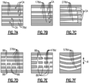
- Figure 8 depicts a method for fabricating the airfoil section 60, which is generally a fiber ply lay-up process.
- the fiber plies that are laid-up are initially devoid of any ceramic matrix material.
- Core fiber plies 68 are identified on the left side of the figure. These core fiber plies 68 are first laid-up to form what will be the radial tube 72 that circumscribes the internal cavity 61. As an example, the core fiber plies 68 are sequentially laid-up on a mandrel or other support surface. After lay-up of the initial, inner-most core fiber ply 68, the next core fiber plies 68 are wrapped around the initial core fiber ply 68.
Landscapes
- Engineering & Computer Science (AREA)
- Chemical & Material Sciences (AREA)
- Mechanical Engineering (AREA)
- General Engineering & Computer Science (AREA)
- Materials Engineering (AREA)
- Ceramic Engineering (AREA)
- Manufacturing & Machinery (AREA)
- Structural Engineering (AREA)
- Organic Chemistry (AREA)
- Chemical Kinetics & Catalysis (AREA)
- Physics & Mathematics (AREA)
- Fluid Mechanics (AREA)
- Composite Materials (AREA)
- Turbine Rotor Nozzle Sealing (AREA)
Applications Claiming Priority (1)
| Application Number | Priority Date | Filing Date | Title |
|---|---|---|---|
| US18/480,698 US20250116193A1 (en) | 2023-10-04 | 2023-10-04 | CMC Airfoil with Cooling Passage Having Multi-Dimensional Plenum |
Publications (1)
| Publication Number | Publication Date |
|---|---|
| EP4534802A1 true EP4534802A1 (fr) | 2025-04-09 |
Family
ID=92973541
Family Applications (1)
| Application Number | Title | Priority Date | Filing Date |
|---|---|---|---|
| EP24204354.5A Pending EP4534802A1 (fr) | 2023-10-04 | 2024-10-02 | Aube, moteur à turbine à gaz et procédé pour fabriquer une aube |
Country Status (2)
| Country | Link |
|---|---|
| US (1) | US20250116193A1 (fr) |
| EP (1) | EP4534802A1 (fr) |
Families Citing this family (1)
| Publication number | Priority date | Publication date | Assignee | Title |
|---|---|---|---|---|
| US12584418B2 (en) * | 2024-08-15 | 2026-03-24 | Rtx Corporation | CMC component with cooling cavity |
Citations (3)
| Publication number | Priority date | Publication date | Assignee | Title |
|---|---|---|---|---|
| US20170328216A1 (en) * | 2016-05-11 | 2017-11-16 | General Electric Company | Ceramic matrix composite airfoil cooling |
| US20180328189A1 (en) * | 2017-05-11 | 2018-11-15 | General Electric Company | Cmc components having microchannels and methods for forming microchannels in cmc components |
| US20190330988A1 (en) * | 2018-04-25 | 2019-10-31 | Rolls-Royce Plc | Cmc aerofoil |
-
2023
- 2023-10-04 US US18/480,698 patent/US20250116193A1/en active Pending
-
2024
- 2024-10-02 EP EP24204354.5A patent/EP4534802A1/fr active Pending
Patent Citations (3)
| Publication number | Priority date | Publication date | Assignee | Title |
|---|---|---|---|---|
| US20170328216A1 (en) * | 2016-05-11 | 2017-11-16 | General Electric Company | Ceramic matrix composite airfoil cooling |
| US20180328189A1 (en) * | 2017-05-11 | 2018-11-15 | General Electric Company | Cmc components having microchannels and methods for forming microchannels in cmc components |
| US20190330988A1 (en) * | 2018-04-25 | 2019-10-31 | Rolls-Royce Plc | Cmc aerofoil |
Also Published As
| Publication number | Publication date |
|---|---|
| US20250116193A1 (en) | 2025-04-10 |
Similar Documents
| Publication | Publication Date | Title |
|---|---|---|
| EP4283095B1 (fr) | Aube stratifiée en cmc avec gouttes de pli | |
| EP4180633B1 (fr) | Pale d'une turbine à gaz constitué de plis de fibres ayant des doigts interdigités à l'extrémité de fuite | |
| EP4461928A1 (fr) | Aube avec découpes de pli de cmc pour canaux de refroidissement, moteur à turbine à gaz et procédé de fabrication d'une aube | |
| EP4461713A1 (fr) | Segment d'arc d'étanchéité avec découpes de pli de cmc pour canaux de refroidissement, moteur à turbine à gaz et procédé de fabrication d'un segment d'arc d'étanchéité | |
| EP4534802A1 (fr) | Aube, moteur à turbine à gaz et procédé pour fabriquer une aube | |
| EP4534803A1 (fr) | Aube, moteur à turbine à gaz et procédé pour fabriquer une aube | |
| EP4545755A1 (fr) | Aube et moteur à turbine à gaz | |
| EP3825519B1 (fr) | Ensemble de profil aérodynamique d'aube pour moteur à turbine à gaz, aube fixe correspondante et procédé d'assemblage d'une aube fixe | |
| EP3825516B1 (fr) | Ensemble d'aube directrice et procédé d'assemblage correspondant | |
| EP3974617A1 (fr) | Aube de turbine à gaz avec trous de refroidissement à 3 zones avec des distances differentes respectivement | |
| EP4461925A1 (fr) | Procédé pour surface portante en cmc utilisant un tube central en tissu céramique rigidifié | |
| EP4083378B1 (fr) | Ensemble surface portante comportant des anneaux en composite renforcé de fibres | |
| US12044143B2 (en) | Gas turbine engine component with manifold cavity and metering inlet orifices | |
| US11098608B2 (en) | CMC BOAS with internal support structure | |
| EP4306772B1 (fr) | Multit d'aube de surface portante à couches de fibres entrelacées | |
| EP4545756A1 (fr) | Aube et moteur à turbine à gaz | |
| US12448708B2 (en) | Extended inner profile for mandrel for use in forming braided CMC structures | |
| EP4067620B1 (fr) | Profil d'aube avec nervures espacées radialement et languettes imbriquées, et moteur à turbine à gaz | |
| US12241387B1 (en) | Tilted CMC vane arc segment | |
| EP3808940B1 (fr) | Surface portante en cmc pour un moteur à turbine à gaz comportant des trous de refroidissement |
Legal Events
| Date | Code | Title | Description |
|---|---|---|---|
| PUAI | Public reference made under article 153(3) epc to a published international application that has entered the european phase |
Free format text: ORIGINAL CODE: 0009012 |
|
| STAA | Information on the status of an ep patent application or granted ep patent |
Free format text: STATUS: THE APPLICATION HAS BEEN PUBLISHED |
|
| AK | Designated contracting states |
Kind code of ref document: A1 Designated state(s): AL AT BE BG CH CY CZ DE DK EE ES FI FR GB GR HR HU IE IS IT LI LT LU LV MC ME MK MT NL NO PL PT RO RS SE SI SK SM TR |
|
| STAA | Information on the status of an ep patent application or granted ep patent |
Free format text: STATUS: REQUEST FOR EXAMINATION WAS MADE |
|
| 17P | Request for examination filed |
Effective date: 20251009 |
|
| GRAP | Despatch of communication of intention to grant a patent |
Free format text: ORIGINAL CODE: EPIDOSNIGR1 |
|
| STAA | Information on the status of an ep patent application or granted ep patent |
Free format text: STATUS: GRANT OF PATENT IS INTENDED |
|
| RIC1 | Information provided on ipc code assigned before grant |
Ipc: F01D 5/28 20060101AFI20260116BHEP Ipc: F01D 5/18 20060101ALI20260116BHEP Ipc: F01D 9/06 20060101ALI20260116BHEP Ipc: C04B 35/80 20060101ALI20260116BHEP |
|
| INTG | Intention to grant announced |
Effective date: 20260129 |