EP4534836A1 - Struktur eines sektionalen klingenmoduls und herstellungsverfahren dafür - Google Patents
Struktur eines sektionalen klingenmoduls und herstellungsverfahren dafür Download PDFInfo
- Publication number
- EP4534836A1 EP4534836A1 EP23928313.8A EP23928313A EP4534836A1 EP 4534836 A1 EP4534836 A1 EP 4534836A1 EP 23928313 A EP23928313 A EP 23928313A EP 4534836 A1 EP4534836 A1 EP 4534836A1
- Authority
- EP
- European Patent Office
- Prior art keywords
- blade
- blade shell
- web
- ring
- hole
- Prior art date
- Legal status (The legal status is an assumption and is not a legal conclusion. Google has not performed a legal analysis and makes no representation as to the accuracy of the status listed.)
- Pending
Links
Images




Classifications
-
- B—PERFORMING OPERATIONS; TRANSPORTING
- B29—WORKING OF PLASTICS; WORKING OF SUBSTANCES IN A PLASTIC STATE IN GENERAL
- B29C—SHAPING OR JOINING OF PLASTICS; SHAPING OF MATERIAL IN A PLASTIC STATE, NOT OTHERWISE PROVIDED FOR; AFTER-TREATMENT OF THE SHAPED PRODUCTS, e.g. REPAIRING
- B29C70/00—Shaping composites, i.e. plastics material comprising reinforcements, fillers or preformed parts, e.g. inserts
- B29C70/04—Shaping composites, i.e. plastics material comprising reinforcements, fillers or preformed parts, e.g. inserts comprising reinforcements only, e.g. self-reinforcing plastics
- B29C70/28—Shaping operations therefor
- B29C70/40—Shaping or impregnating by compression not applied
- B29C70/42—Shaping or impregnating by compression not applied for producing articles of definite length, i.e. discrete articles
-
- B—PERFORMING OPERATIONS; TRANSPORTING
- B29—WORKING OF PLASTICS; WORKING OF SUBSTANCES IN A PLASTIC STATE IN GENERAL
- B29C—SHAPING OR JOINING OF PLASTICS; SHAPING OF MATERIAL IN A PLASTIC STATE, NOT OTHERWISE PROVIDED FOR; AFTER-TREATMENT OF THE SHAPED PRODUCTS, e.g. REPAIRING
- B29C70/00—Shaping composites, i.e. plastics material comprising reinforcements, fillers or preformed parts, e.g. inserts
- B29C70/04—Shaping composites, i.e. plastics material comprising reinforcements, fillers or preformed parts, e.g. inserts comprising reinforcements only, e.g. self-reinforcing plastics
- B29C70/28—Shaping operations therefor
- B29C70/54—Component parts, details or accessories; Auxiliary operations, e.g. feeding or storage of prepregs or SMC after impregnation or during ageing
-
- B—PERFORMING OPERATIONS; TRANSPORTING
- B29—WORKING OF PLASTICS; WORKING OF SUBSTANCES IN A PLASTIC STATE IN GENERAL
- B29D—PRODUCING PARTICULAR ARTICLES FROM PLASTICS OR FROM SUBSTANCES IN A PLASTIC STATE
- B29D99/00—Subject matter not provided for in other groups of this subclass
- B29D99/0003—Producing profiled members, e.g. beams
-
- B—PERFORMING OPERATIONS; TRANSPORTING
- B29—WORKING OF PLASTICS; WORKING OF SUBSTANCES IN A PLASTIC STATE IN GENERAL
- B29D—PRODUCING PARTICULAR ARTICLES FROM PLASTICS OR FROM SUBSTANCES IN A PLASTIC STATE
- B29D99/00—Subject matter not provided for in other groups of this subclass
- B29D99/0025—Producing blades or the like, e.g. blades for turbines, propellers, or wings
- B29D99/0028—Producing blades or the like, e.g. blades for turbines, propellers, or wings hollow blades
-
- F—MECHANICAL ENGINEERING; LIGHTING; HEATING; WEAPONS; BLASTING
- F03—MACHINES OR ENGINES FOR LIQUIDS; WIND, SPRING, OR WEIGHT MOTORS; PRODUCING MECHANICAL POWER OR A REACTIVE PROPULSIVE THRUST, NOT OTHERWISE PROVIDED FOR
- F03D—WIND MOTORS
- F03D1/00—Wind motors with rotation axis substantially parallel to the air flow entering the rotor
- F03D1/06—Rotors
- F03D1/065—Rotors characterised by their construction elements
- F03D1/0675—Rotors characterised by their construction elements of the blades
- F03D1/0677—Longitudinally segmented blades; Connectors therefor
-
- F—MECHANICAL ENGINEERING; LIGHTING; HEATING; WEAPONS; BLASTING
- F03—MACHINES OR ENGINES FOR LIQUIDS; WIND, SPRING, OR WEIGHT MOTORS; PRODUCING MECHANICAL POWER OR A REACTIVE PROPULSIVE THRUST, NOT OTHERWISE PROVIDED FOR
- F03D—WIND MOTORS
- F03D1/00—Wind motors with rotation axis substantially parallel to the air flow entering the rotor
- F03D1/06—Rotors
- F03D1/065—Rotors characterised by their construction elements
- F03D1/0675—Rotors characterised by their construction elements of the blades
- F03D1/0679—Load carrying structures, e.g. beams
- F03D1/0681—Spar caps
-
- B—PERFORMING OPERATIONS; TRANSPORTING
- B29—WORKING OF PLASTICS; WORKING OF SUBSTANCES IN A PLASTIC STATE IN GENERAL
- B29L—INDEXING SCHEME ASSOCIATED WITH SUBCLASS B29C, RELATING TO PARTICULAR ARTICLES
- B29L2031/00—Other particular articles
- B29L2031/08—Blades for rotors, stators, fans, turbines or the like, e.g. screw propellers
-
- F—MECHANICAL ENGINEERING; LIGHTING; HEATING; WEAPONS; BLASTING
- F05—INDEXING SCHEMES RELATING TO ENGINES OR PUMPS IN VARIOUS SUBCLASSES OF CLASSES F01-F04
- F05B—INDEXING SCHEME RELATING TO WIND, SPRING, WEIGHT, INERTIA OR LIKE MOTORS, TO MACHINES OR ENGINES FOR LIQUIDS COVERED BY SUBCLASSES F03B, F03D AND F03G
- F05B2240/00—Components
- F05B2240/20—Rotors
- F05B2240/30—Characteristics of rotor blades, i.e. of any element transforming dynamic fluid energy to or from rotational energy and being attached to a rotor
- F05B2240/302—Segmented or sectional blades
-
- F—MECHANICAL ENGINEERING; LIGHTING; HEATING; WEAPONS; BLASTING
- F05—INDEXING SCHEMES RELATING TO ENGINES OR PUMPS IN VARIOUS SUBCLASSES OF CLASSES F01-F04
- F05B—INDEXING SCHEME RELATING TO WIND, SPRING, WEIGHT, INERTIA OR LIKE MOTORS, TO MACHINES OR ENGINES FOR LIQUIDS COVERED BY SUBCLASSES F03B, F03D AND F03G
- F05B2260/00—Function
- F05B2260/30—Retaining components in desired mutual position
- F05B2260/301—Retaining bolts or nuts
-
- Y—GENERAL TAGGING OF NEW TECHNOLOGICAL DEVELOPMENTS; GENERAL TAGGING OF CROSS-SECTIONAL TECHNOLOGIES SPANNING OVER SEVERAL SECTIONS OF THE IPC; TECHNICAL SUBJECTS COVERED BY FORMER USPC CROSS-REFERENCE ART COLLECTIONS [XRACs] AND DIGESTS
- Y02—TECHNOLOGIES OR APPLICATIONS FOR MITIGATION OR ADAPTATION AGAINST CLIMATE CHANGE
- Y02E—REDUCTION OF GREENHOUSE GAS [GHG] EMISSIONS, RELATED TO ENERGY GENERATION, TRANSMISSION OR DISTRIBUTION
- Y02E10/00—Energy generation through renewable energy sources
- Y02E10/70—Wind energy
- Y02E10/72—Wind turbines with rotation axis in wind direction
Definitions
- the present invention relates to the technical field of wind turbine blades, in particular to a segmented blade module structure and a molding method thereof.
- wind energy As a renewable energy, wind energy has the advantages of low development cost, mature technology, and wide distribution, making it a key direction for the development of renewable energy.
- the improvement of the aerodynamic shape of wind turbine blades and the increase of blade size are important means to increase the power generation of wind turbines. Therefore, the gradual move towards large-scale wind turbines is a trend in the development of wind power technology.
- areas rich in wind resources are often remote and inaccessible areas with poor transportation conditions which limit the large-scale wind turbines.
- wind turbine blades are generally manufactured using fiber-reinforced polymer based composite materials.
- the production process of composite blades has strict environmental and process requirements, and the composite materials used in ultra long blades are more sensitive to production conditions, making it difficult to control blade quality.
- it is an effective method to solve the problem of large-scale wind turbines by adopting segmented blade structure, characterized by production in existing factories, transportation in segments and assembly on site.
- the overweight blade structure is not conducive to maintaining stable operation when the wind turbine is running. Therefore, ensuring the structural performance of the blade while reducing the weight and cost of the blade has become another technical problem in the development of wind power technology.
- the present invention provides a segmented blade module structure and a molding method thereof to effectively solve the problems discussed above.
- a segmented blade module structure comprises a blade shell, a beam and a web provided in the blade shell, wherein the blade shell comprises a windward surface and a leeward surface that are integrally provided, the beam is attached to the blade shell and supports the windward surface and leeward surface by the web.
- the blade shell is provided along its chord length direction in form of a leading edge portion, a middle portion, and a trailing edge portion, and the beam comprises a connecting beam, a trailing edge beam, and an auxiliary beam plate, wherein the connecting beam is provided corresponding to a middle portion of the windward surface and the leeward surface, the trailing edge beam is provided corresponding to the trailing edge portion, and the auxiliary beam plate is embedded at a notch portion of the connecting beam as well as between the connecting beam and the trailing edge beam.
- connection structure is provided at one end of the connecting beam, and two adjacent blade modules are fixedly connected by a connecting piece provided in the connection structure.
- the web is provided along the axial direction of the blade shell, and a plurality of the webs is provided in the chord direction of the blade shell.
- the two connecting plates of the web located at the leading edge portion abut with the inner sides of the windward surface and the leeward surface respectively, and the two connecting plates of the web located at the middle portion abut with the two connecting beams respectively.
- connecting plates are fixedly connected to the blade shell or the connecting beam by a structural adhesive.
- connection structure is provided on the ring beam, comprising a plurality of first ring holes and a plurality of second ring holes provided along the circumferential direction of the blade shell, wherein the first and second ring holes are staggered, the first ring hole is closer to an end face of the ring beam, the first ring hole is provided in form of a circular through hole, and the second ring hole is provided in form of a gourd shaped through hole.
- the first ring hole and the second ring hole are communicated with a first axial hole and a second axial hole respectively, and both the first axial hole and the second axial hole are provided on the end face of the ring beam and are axially extended along the blade shell.
- the connecting piece comprises a cylindrical nut, a double-headed bolt, a semi-cylindrical spacer and a round nut.
- the cylindrical nut and the semi-cylindrical spacer are disposed in the first ring hole and the second ring hole respectively.
- a T-shaped beam is provided between two adjacent auxiliary beam plates provided along the circumferential direction of the blade shell, wherein the T-shaped beam is fixedly connected to the two auxiliary beam plates through a horizontal plate perpendicular to its longitudinal plate.
- a lap is provided on the side of the auxiliary beam plate facing the blade shell corresponding to the horizontal plate.
- the lap is concave towards its side away from the blade shell by a depth adapted to the thickness of the horizontal plate.
- a method for molding segmented blade module structure applied to the segmented blade module structure described above comprises the following steps:
- a web is provided at the main spar cap and the auxiliary spar cap of the connecting beam respectively.
- the beam and the web integrally formed of composite materials constitute the bearing frame, wherein the beam is attached to the inner wall of the blade shell, so that the bearing frame forms a contour shape conforming to the blade, and the blade shell is formed by a skin wrapped on the bearing frame.
- the auxiliary beam plate in cooperation with the connecting beam and the trailing edge beam, is arranged corresponding to the area from the middle portion to the trailing edge portion of the blade shell to ensure that there is sufficient contact area between the beam and the blade shell to avoid instability of the blade shell, ensuring the structural stability of the segmented blade module.
- the bearing frame is made of composite materials, which can ensure the structural stability of the blade module and further realize the lightweight design of the blade module.
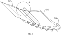
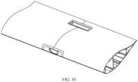
- FIGS. 1 to 10 show a segmented blade module structure comprising a blade shell 1, a beam 2 and a web 3 provided in the blade shell.
- the blade shell 1 comprises a windward surface 11 and a leeward surface 12 that are integrally provided.
- the beam 2 is attached to the blade shell 1 and supports the windward surface 11 and leeward surface 12 by the web 3.
- the blade shell 1 is provided along its chord length direction in form of a leading edge portion 13, a middle portion 14, and a trailing edge portion 15, and the beam 2 comprises a connecting beam 21, a trailing edge beam 22, and an auxiliary beam plate 23.
- the connecting beam 21 is provided corresponding to a middle portion 14 of the windward surface 11 and the leeward surface 12, the trailing edge beam 22 is provided corresponding to the trailing edge portion 15, and the auxiliary beam plate 23 is embedded at a notch portion 214 of the connecting beam 21 as well as between the connecting beam 21 and the trailing edge beam 22.
- a connection structure 24 is provided at one end of the connecting beam 21, and two adjacent blade modules are fixedly connected by a connecting piece 25 provided in the connection structure 24.
- the beam and the web integrally formed of composite materials constitute the bearing frame, wherein the beam 2 is attached to the inner wall of the blade shell 1, so that the bearing frame forms a contour shape conforming to the blade, and the blade shell is formed by a skin wrapped on the bearing frame.
- the auxiliary beam plate 23, in cooperation with the connecting beam 21 and the trailing edge beam 22, is arranged corresponding to the area from the middle portion 14 to the trailing edge portion 15 of the blade shell 1 to ensure that there is sufficient contact area between the beam 2 and the blade shell 1 to avoid instability of the blade shell 1, ensuring the structural stability of the segmented blade module.
- the bearing frame is made of composite materials, which can ensure the structural stability of the blade module and further realize the lightweight design of the blade module.
- the connecting beam 21 is provided between the blade shell 1 and the web 3, and the surfaces on both sides of the connecting beam 21 are fixedly connected to the web 3 and the blade shell 1 to ensure the structural stability of the connecting beam 21.
- the connection structure 24 connecting two adjacent segmented blade modules is provided at the connecting beam 21 to ensure a stable connection of the two blade modules.
- the two connecting plates 32 of the web 3 located at the leading edge portion 13 abut with the inner sides of the windward surface 11 and the leeward surface 12 respectively, and the two connecting plates 32 of the web 3 located at the middle portion 14 abut with the two connecting beams 21 respectively.
- the connecting plates 32 are fixedly connected to the blade shell 1 or the connecting beam 21 by a structural adhesive.
- the supporting vertical plate 31 on the web 3 is provided as a straight plate along the blade axis, and an arc groove is provided at one end of the supporting vertical plate 31 close to the connecting end of the blade module, which can eliminate stress concentration at the end of the web 3 and improve the bearing capacity of the web 3.
- the auxiliary beam plate 23 is also embedded in the notch portion 214 of the connecting beam 21, so that the edge of the connecting beam 21 can abut with the auxiliary beam plate 23 in the circumferential direction of the blade to realize circumferential transmission of the force from the blade shell 1 on the bearing frame, thus ensuring the stress stability of the bearing structure while increasing the contact area between the bearing structure and the blade shell 1 and improving the structural stability of the blade module.
- the connection structure 24 is provided on the ring beam 211, comprising a plurality of first ring holes 241 and a plurality of second ring holes 242 provided along the circumferential direction of the blade shell 1.
- the first and second ring holes 241, 242 are staggered and the first ring hole 241 is closer to an end face of the ring beam 211.
- the first ring hole 241 is provided in form of a circular through hole
- the second ring hole 242 is provided in form of a gourd shaped through hole.
- the first ring hole 241 and the second ring hole 242 are communicated with a first axial hole 243 and a second axial hole 244 respectively, and both the first axial hole 243 and the second axial hole 244 are provided on the end face of the ring beam 211 and are axially extended along the blade shell 1.
- the first ring hole 241 and the second ring hole 242 are respectively provided at different circumferential positions of the blade.
- the first ring hole 241 and the second ring hole 242 are staggered so that the connection structures 24 on two adjacent blade modules are uniformly distributed, thereby avoiding damage on one side of the two connecting beams 21 in the two blade modules and ensuring the bearing capacity of the connecting beams 21.
- the connecting piece 25 comprises a cylindrical nut 251, a double-headed bolt 252, a semi-cylindrical spacer 253 and a round nut 254.
- the cylindrical nut 251 and the semi-cylindrical spacer 253 are disposed in the first ring hole 241 and the second ring hole 242 respectively.
- the double-headed bolt 252 is disposed in the first axial hole 243 and the second axial hole 244 respectively, with one end of the double-headed bolt 242 screwed to the cylindrical nut 251, or screwed to the round nut 254 passing through the semi-cylindrical spacer 253.
- the gourd-shaped through hole facilitates the tightening and fixing of the round nut 254 and the end of the double-headed bolt 252, ensuring that there is no space restriction when using a tool to tighten the round nut 254, making it easy to operate.
- a T-shaped beam 26 is provided between two adjacent auxiliary beam plates 23 provided along the circumferential direction of the blade shell 1.
- the T-shaped beam 26 is fixedly connected to the two auxiliary beam plates 24 through a horizontal plate 262 perpendicular to its longitudinal plate 261.
- a lap 231 is provided on the side of the auxiliary beam plate 23 facing the blade shell 1 corresponding to the horizontal plate 262.
- the lap 231 is concave towards its side away from the blade shell 1 by a depth adapted to the thickness of the horizontal plate 262. This ensures that the connection surface between the beam 2 and the blade shell 1 is flat.
- a method for molding segmented blade module structure comprises the following steps:
- the axial length of the connecting beam 21 is configured to be the same with the axial length of the blade shell 1, and the length of the trailing edge beam 22 is configured to be larger than or smaller than the axial length of the blade shell 1.
- the trailing edge beam 22 is configured to extend from or retract into the end face of the blade shell 1, and the trailing edge beams 22 in two adjacent blade modules abut with each other at an end thereof, so that during the connection process of the two blade modules, an insertion structure is formed between the trailing edge beam 22 extending from the end face of the blade shell 1 and the trailing edge portion 15 of the other blade shell 1, enhancing the connection strength and stability.
Landscapes
- Engineering & Computer Science (AREA)
- Mechanical Engineering (AREA)
- Chemical & Material Sciences (AREA)
- Life Sciences & Earth Sciences (AREA)
- Sustainable Development (AREA)
- Sustainable Energy (AREA)
- Combustion & Propulsion (AREA)
- General Engineering & Computer Science (AREA)
- Composite Materials (AREA)
- Wind Motors (AREA)
Applications Claiming Priority (2)
| Application Number | Priority Date | Filing Date | Title |
|---|---|---|---|
| CN202310267132.XA CN115977867B (zh) | 2023-03-20 | 2023-03-20 | 一种分段式叶片模块结构及其成型方法 |
| PCT/CN2023/124314 WO2024193008A1 (zh) | 2023-03-20 | 2023-10-12 | 一种分段式叶片模块结构及其成型方法 |
Publications (2)
| Publication Number | Publication Date |
|---|---|
| EP4534836A1 true EP4534836A1 (de) | 2025-04-09 |
| EP4534836A4 EP4534836A4 (de) | 2025-12-24 |
Family
ID=85965142
Family Applications (1)
| Application Number | Title | Priority Date | Filing Date |
|---|---|---|---|
| EP23928313.8A Pending EP4534836A4 (de) | 2023-03-20 | 2023-10-12 | Struktur eines sektionalen klingenmoduls und herstellungsverfahren dafür |
Country Status (4)
| Country | Link |
|---|---|
| US (1) | US12392318B2 (de) |
| EP (1) | EP4534836A4 (de) |
| CN (1) | CN115977867B (de) |
| WO (1) | WO2024193008A1 (de) |
Families Citing this family (4)
| Publication number | Priority date | Publication date | Assignee | Title |
|---|---|---|---|---|
| CN115977866B (zh) * | 2023-03-20 | 2023-05-23 | 新创碳谷集团有限公司 | 一种模块化风电叶片及其连接结构 |
| CN115977867B (zh) | 2023-03-20 | 2023-06-09 | 新创碳谷集团有限公司 | 一种分段式叶片模块结构及其成型方法 |
| CN116104688B (zh) * | 2023-04-17 | 2023-06-27 | 新创碳谷集团有限公司 | 一种两段式风电叶片连接结构 |
| CN118088375A (zh) * | 2024-03-14 | 2024-05-28 | 汇创新能源科技(阜宁)有限公司 | 一种风电叶片壳体t型拉挤梁连接结构 |
Family Cites Families (29)
| Publication number | Priority date | Publication date | Assignee | Title |
|---|---|---|---|---|
| DE10235496B4 (de) * | 2002-08-02 | 2015-07-30 | General Electric Co. | Verfahren zum Herstellen eines Rotorblattes, Rotorblatt und Windenergieanlage |
| GB0717690D0 (en) * | 2007-09-11 | 2007-10-17 | Blade Dynamics Ltd | Wind turbine blade |
| DK2358998T3 (en) * | 2008-12-05 | 2017-10-30 | Vestas Wind Sys As | EFFICIENT WINDOWS, WINDOWS, AND ASSOCIATED SYSTEMS AND PROCEDURES FOR MANUFACTURING, INSTALLING AND USING |
| EP2405130A1 (de) * | 2010-07-08 | 2012-01-11 | Lm Glasfiber A/S | Notchreduzierte Verbundstoffverbindung |
| KR20130039468A (ko) * | 2011-10-12 | 2013-04-22 | 삼성중공업 주식회사 | 풍력 발전기의 블레이드 및 이의 제작 방법 |
| ES2385726B1 (es) * | 2012-05-10 | 2013-06-11 | Manuel Torres Martínez | Pala de aerogenerador formada por tramos |
| DE102012111219B4 (de) * | 2012-11-21 | 2016-06-16 | Spitzner Engineers GmbH | Windenergieanlagenkomponente |
| US9506452B2 (en) * | 2013-08-28 | 2016-11-29 | General Electric Company | Method for installing a shear web insert within a segmented rotor blade assembly |
| CN103600498B (zh) * | 2013-11-07 | 2017-06-23 | 吉林重通成飞新材料股份公司 | 分段式风电叶片的制造以及装配方法 |
| US20150369211A1 (en) * | 2014-06-19 | 2015-12-24 | General Electric Company | Wind blade tip joint |
| WO2016075619A1 (en) * | 2014-11-10 | 2016-05-19 | Polytech A/S | Polyurethane material, process for preparing such material and protective cover for wind turbine blade |
| DE102014118004B3 (de) * | 2014-12-05 | 2016-03-31 | Deutsches Zentrum für Luft- und Raumfahrt e.V. | Rotorblatt für Windkraftanlagen |
| GB201509991D0 (en) * | 2015-06-09 | 2015-07-22 | Vestas Wind Sys As | Modular wind turbine blades |
| US9951751B2 (en) * | 2015-09-30 | 2018-04-24 | General Electric Company | Segmented wind turbine rotor blade with rod and tube joint connection |
| CN105526044A (zh) * | 2015-12-24 | 2016-04-27 | 东方电气风电有限公司 | 风力发电机分段组装叶片的连接结构及其制作方法 |
| EP3563053B1 (de) * | 2016-12-28 | 2020-11-18 | Vestas Wind Systems A/S | Verbindungsgelenk für ein sektionales windturbinenrotorblatt und zugehörige verfahren |
| US10830206B2 (en) * | 2017-02-03 | 2020-11-10 | General Electric Company | Methods for manufacturing wind turbine rotor blades and components thereof |
| EP3376024A1 (de) * | 2017-03-13 | 2018-09-19 | Nordex Energy GmbH | Teilbares windenergieanlagenrotorblatt mit bolzenverbindung |
| WO2020119874A1 (en) * | 2018-12-14 | 2020-06-18 | Vestas Wind Systems A/S | Wind turbine blade |
| EP3712425B1 (de) * | 2019-03-21 | 2024-09-11 | Siemens Gamesa Renewable Energy A/S | Holmkappe einer windturbinenschaufel, windturbinenschaufel und windturbine |
| CN112012878A (zh) * | 2019-05-31 | 2020-12-01 | 江苏金风科技有限公司 | 腹板、叶片、成型方法以及风力发电机组 |
| CN211692705U (zh) * | 2020-02-26 | 2020-10-16 | 新疆金风科技股份有限公司 | 叶片及风力发电机组 |
| EP3925768A1 (de) * | 2020-06-15 | 2021-12-22 | Siemens Gamesa Renewable Energy A/S | Verfahren zur herstellung einer windturbinenschaufel und dornwerkzeug |
| CN112360681A (zh) * | 2020-10-29 | 2021-02-12 | 中材科技(邯郸)风电叶片有限公司 | 风电叶片及生产工艺 |
| EP4392244B1 (de) * | 2021-08-25 | 2025-12-10 | LM Wind Power A/S | Dornvorrichtung zur herstellung einer segmentierten windturbinenschaufel und verfahren zur herstellung eines hohlen holms |
| CN113787658B (zh) * | 2021-09-10 | 2022-06-14 | 常州市宏发纵横新材料科技股份有限公司 | 模块化风电叶片及其制造方法 |
| CN113958447B (zh) * | 2021-11-10 | 2022-07-22 | 常州市宏发纵横新材料科技股份有限公司 | 一种模块化风电叶片弦向分块连接结构 |
| CN115573854B (zh) * | 2022-10-25 | 2023-04-07 | 新创碳谷集团有限公司 | 一种模块化风电叶片及制造方法 |
| CN115977867B (zh) * | 2023-03-20 | 2023-06-09 | 新创碳谷集团有限公司 | 一种分段式叶片模块结构及其成型方法 |
-
2023
- 2023-03-20 CN CN202310267132.XA patent/CN115977867B/zh active Active
- 2023-10-12 EP EP23928313.8A patent/EP4534836A4/de active Pending
- 2023-10-12 WO PCT/CN2023/124314 patent/WO2024193008A1/zh not_active Ceased
-
2024
- 2024-09-07 US US18/827,683 patent/US12392318B2/en active Active
Also Published As
| Publication number | Publication date |
|---|---|
| US20240426272A1 (en) | 2024-12-26 |
| WO2024193008A1 (zh) | 2024-09-26 |
| EP4534836A4 (de) | 2025-12-24 |
| US12392318B2 (en) | 2025-08-19 |
| CN115977867B (zh) | 2023-06-09 |
| CN115977867A (zh) | 2023-04-18 |
Similar Documents
| Publication | Publication Date | Title |
|---|---|---|
| US12392318B2 (en) | Segmented blade module structure and molding method thereof | |
| US12510050B2 (en) | Modular wind turbine blade and connection structure thereof | |
| US9605651B2 (en) | Spar assembly for a wind turbine rotor blade | |
| US20180051672A1 (en) | Jointed rotor blade for wind turbine | |
| CN113958447B (zh) | 一种模块化风电叶片弦向分块连接结构 | |
| EP3997331B1 (de) | Verbindung für geteiltes windturbinenblatt | |
| EP4004363B1 (de) | Verbindung für geteiltes windturbinenblatt | |
| US12049865B2 (en) | Wind turbine blade with a plurality of shear webs | |
| EP3997332B1 (de) | Verbindung für geteiltes windturbinenblatt | |
| JP2005147086A (ja) | 水平軸風車のブレード | |
| CN112443451A (zh) | 一种新型风力发电叶片 | |
| CN224260462U (zh) | 一种轮毂及风轮 | |
| CN103629055B (zh) | 一种可拆卸的风力机叶片及其装配方法 | |
| CN223662004U (zh) | 一种风电叶片及风轮 | |
| CN220748457U (zh) | 一种装配式风机塔架 | |
| CN207609513U (zh) | 用于分段式叶片的连接装置、分段式叶片及风力发电机组 | |
| CN219570247U (zh) | 一种分段式叶片模块 | |
| CN218894723U (zh) | 一种拼接式加宽风电叶片 | |
| CN118745974B (zh) | 一种塔架过渡塔节、塔架及风力发电机组 | |
| CN223739553U (zh) | 一种风能发电用叶片 | |
| CN116006409B (zh) | 一种焊接t形约束肋板的多腔钢板混凝土组合筒及施工方法 | |
| CN222162816U (zh) | 一种风力发电用大型风叶 | |
| CN223177665U (zh) | 一种风电叶片内部加强结构 | |
| CN214403859U (zh) | 塔架以及风力发电机组 | |
| US20240295210A1 (en) | A blade for a wind turbine |
Legal Events
| Date | Code | Title | Description |
|---|---|---|---|
| STAA | Information on the status of an ep patent application or granted ep patent |
Free format text: STATUS: THE INTERNATIONAL PUBLICATION HAS BEEN MADE |
|
| PUAI | Public reference made under article 153(3) epc to a published international application that has entered the european phase |
Free format text: ORIGINAL CODE: 0009012 |
|
| STAA | Information on the status of an ep patent application or granted ep patent |
Free format text: STATUS: REQUEST FOR EXAMINATION WAS MADE |
|
| 17P | Request for examination filed |
Effective date: 20241231 |
|
| AK | Designated contracting states |
Kind code of ref document: A1 Designated state(s): AL AT BE BG CH CY CZ DE DK EE ES FI FR GB GR HR HU IE IS IT LI LT LU LV MC ME MK MT NL NO PL PT RO RS SE SI SK SM TR |
|
| STAA | Information on the status of an ep patent application or granted ep patent |
Free format text: STATUS: EXAMINATION IS IN PROGRESS |
|
| A4 | Supplementary search report drawn up and despatched |
Effective date: 20251125 |
|
| RIC1 | Information provided on ipc code assigned before grant |
Ipc: F03D 1/06 20060101AFI20251119BHEP Ipc: B29L 31/08 20060101ALI20251119BHEP Ipc: B29D 99/00 20100101ALI20251119BHEP Ipc: B29C 70/54 20060101ALI20251119BHEP Ipc: B29C 70/42 20060101ALI20251119BHEP |
|
| 17Q | First examination report despatched |
Effective date: 20251128 |