EP4534996A2 - Anschlussstück für fluidische kupplung in einem chromatografiesystem - Google Patents
Anschlussstück für fluidische kupplung in einem chromatografiesystem Download PDFInfo
- Publication number
- EP4534996A2 EP4534996A2 EP24218891.0A EP24218891A EP4534996A2 EP 4534996 A2 EP4534996 A2 EP 4534996A2 EP 24218891 A EP24218891 A EP 24218891A EP 4534996 A2 EP4534996 A2 EP 4534996A2
- Authority
- EP
- European Patent Office
- Prior art keywords
- tube
- endface
- seal body
- fitting
- collar
- Prior art date
- Legal status (The legal status is an assumption and is not a legal conclusion. Google has not performed a legal analysis and makes no representation as to the accuracy of the status listed.)
- Pending
Links
Images



Classifications
-
- G—PHYSICS
- G01—MEASURING; TESTING
- G01N—INVESTIGATING OR ANALYSING MATERIALS BY DETERMINING THEIR CHEMICAL OR PHYSICAL PROPERTIES
- G01N30/00—Investigating or analysing materials by separation into components using adsorption, absorption or similar phenomena or using ion-exchange, e.g. chromatography or field flow fractionation
- G01N30/02—Column chromatography
- G01N30/60—Construction of the column
- G01N30/6004—Construction of the column end pieces
- G01N30/6026—Fluid seals
-
- F—MECHANICAL ENGINEERING; LIGHTING; HEATING; WEAPONS; BLASTING
- F16—ENGINEERING ELEMENTS AND UNITS; GENERAL MEASURES FOR PRODUCING AND MAINTAINING EFFECTIVE FUNCTIONING OF MACHINES OR INSTALLATIONS; THERMAL INSULATION IN GENERAL
- F16L—PIPES; JOINTS OR FITTINGS FOR PIPES; SUPPORTS FOR PIPES, CABLES OR PROTECTIVE TUBING; MEANS FOR THERMAL INSULATION IN GENERAL
- F16L19/00—Joints in which sealing surfaces are pressed together by means of a member, e.g. a swivel nut, screwed on, or into, one of the joint parts
- F16L19/02—Pipe ends provided with collars or flanges, integral with the pipe or not, pressed together by a screwed member
- F16L19/0212—Pipe ends provided with collars or flanges, integral with the pipe or not, pressed together by a screwed member using specially adapted sealing means
-
- F—MECHANICAL ENGINEERING; LIGHTING; HEATING; WEAPONS; BLASTING
- F16—ENGINEERING ELEMENTS AND UNITS; GENERAL MEASURES FOR PRODUCING AND MAINTAINING EFFECTIVE FUNCTIONING OF MACHINES OR INSTALLATIONS; THERMAL INSULATION IN GENERAL
- F16L—PIPES; JOINTS OR FITTINGS FOR PIPES; SUPPORTS FOR PIPES, CABLES OR PROTECTIVE TUBING; MEANS FOR THERMAL INSULATION IN GENERAL
- F16L19/00—Joints in which sealing surfaces are pressed together by means of a member, e.g. a swivel nut, screwed on, or into, one of the joint parts
- F16L19/02—Pipe ends provided with collars or flanges, integral with the pipe or not, pressed together by a screwed member
- F16L19/0206—Pipe ends provided with collars or flanges, integral with the pipe or not, pressed together by a screwed member the collar not being integral with the pipe
Definitions
- Typical fluidic tube fittings for fluidic coupling in LC systems require an open-ended wrench for installation. This can cause issues during installation. If a wrench is unavailable, a user will not be able to apply enough torque for the fitting to properly tighten. Even if a wrench is available, using a tool such as a wrench for installation of a fitting can be difficult for some users and result in over-tightened or under-tightened installations.
- typical tube fittings for fluidic coupling in LC systems often create debris from galling between a compression screw and a gasket and/or ferrule. Galling and debris reduces the life of the fitting.
- Other issues encountered in fittings are that many fittings allow for dead volume to exist between the fitting and a female receiver of a fluidic coupling. This dead space allows for liquid to accumulate without being moved through the fitting and hinders the accuracy of the system.
- Existing fitting systems also include many loose parts, which can create problems for users if parts are lost or dropped.
- a fitting for fluidic coupling in a chromatography system includes a compression screw including an axial bore, a threaded portion, and a drive end; a tube assembly including a tube sleeve and an inner tube disposed through the sleeve, the tube sleeve and the inner tube each extending to an endface of the tube assembly, the tube sleeve including an outer surface; a seal body extending between a first endface and a second endface, the first endface abutting the endface of the tube assembly, the seal body including an outer surface; and a collar secured to the outer surface of the tube sleeve and the outer surface of the seal body.
- the tube sleeve and the inner tube are welded together at the endface.
- seal body is made of at least one of a high temperature polyimide and polyether ether ketone.
- the thin wall portion of the collar is press fit over the reduced outer diameter portion of the tube sleeve, and wherein the thick wall portion of the collar is press fit over the seal body.
- the seal body is configured to deform over the second end when compressed against a surface of a receiver fitting.
- a method of manufacturing a fitting for fluidic coupling in a chromatography system comprises: welding a tube sleeve and an inner tube at an endface of each of the tube sleeve and the inner tube to create a tube assembly having a welded tube assembly endface; and polishing the welded tube assembly endface.
- a method of fluidic coupling in a chromatography system comprises: providing a fitting including: a compression screw including an axial bore, a threaded portion, and a drive end; a tube assembly including a tube sleeve and an inner tube disposed through the sleeve, the tube sleeve and the inner tube each extending to an endface of the tube assembly, the tube sleeve including an outer surface; a seal body extending between a first endface and a second endface, the first endface abutting the endface of the tube assembly, the seal body including an outer surface; and a collar secured to the outer surface of the tube sleeve and the outer surface of the seal body; and fluidically coupling the fitting to a receiver fitting of a liquid chromatography system by hand tightening the compression screw without a tightening tool.
- the retainer cap and the compression screw are configured to rotate about the tube and the ring during tightening of the compression screw in a receiver fitting.
- the seal body includes an inner bore having dimensions that are equal or larger than an inner diameter of the tube body.
- the compression screw is made of a gall resistant stainless steel material.
- the method includes maintaining a fluid tight seal between the first endface of the seal body and the seating surface of the tube assembly; and conveying fluid through the tube and an axial opening of the seal.
- a fluidic coupling in a chromatography system comprises: a fitting for fluidic coupling in a chromatography system comprising: a compression screw including an axial bore, a threaded portion, and a drive end; a tube having body and a greater diameter portion configured to be moved axially with the compressions screw, the tube including a counterbore extending from a front end to a seating surface; and a seal body extending between a first endface and a second endface, the first endface abutting the seating surface of the counterbore, the seal body including an outer surface dimensioned to fit within the counterbore; and a receiver fitting having a threaded bore and an inner bore having a sealing surface at an end opposite the threaded bore, the receiver fitting having a channel extending from the sealing surface to pass a fluid.
- the threaded portion of the compression screw is engaged with the threaded bore of the receiver fitting pushing the second endface of the seal body against the sealing surface of the receiver fitting.
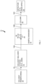
- FIG. 1 shows an embodiment of a liquid chromatography system 10 for separating a sample into its constituents.
- the liquid chromatography system 10 can be an HPLC, UPLC, or SFC system.
- the liquid chromatography system 10 includes a solvent delivery system 12 in fluidic communication with a sample manager 14 (also called an injector or autosampler) through fluidic tube 16A.
- the solvent delivery system 12 includes pumps (not shown) in fluidic communication with solvent (or fluid) reservoirs 18 from which the pumps draw solvents through a fluidic conduit 20, which may be a fluidic conduit, line, tube or channel.
- a chromatography column 22 is in fluidic communication with the sample manager 14 through fluidic tube 16B.
- Fluidic tube 16C couples the output port of the column 22 to a detector 24, for example, a mass spectrometer, a UV detector, or any other detector. Through the fluidic tube 16C, the detector 24 receives the separated components from the column 22 and produces an output from which the identity and quantity of the analytes may be determined. As described herein, at various locations in the liquid chromatography system 10, the fluidic tubes 16A, 16B, 16C are coupled to system components using high pressure fittings. Each fluidic tube 16 refers to a section of tubing rather a single tube. Each tubing section may comprise one tube or multiple tubes joined in series (e.g., by valves, tees, etc.).
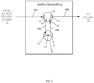
- the sample manager 14 includes an injector valve 26 with a sample loop 28.
- the solvent manager 14 operates in one of two states: a load state and an injection state.
- the load state the position of the injector valve 26 is such that the solvent manager 14 loads the sample into the sample loop 28; in the injection state, the position of the injector valve 26 changes so that solvent manager 14 introduces the sample in the sample loop 28 into the continuously flowing mobile phase arriving from the solvent delivery system 12.
- the injector valve 26 With the injector valve 26 in the injection state, the mobile phase carries the sample into the column 22. To accomplish this, the mobile phase arrives at the injector valve 26 through an input port 30 and leaves the injector valve with the sample through an output port 32.
- the sample manager 14 can further include an auxiliary valve 40 interposed between the solvent delivery system 12 and the injector valve 26 and between the injector valve 26 and the column 22.
- the auxiliary valve 40 provides a fluidic pathway through which the injector valve 26 may vent.
- the fluidic tube 16A couples the solvent delivery system 12 to a first input port 42 of the auxiliary valve 40 and the fluidic tube 16B couples a second output port 44 of the auxiliary valve 40 to the column 22.
- the arrows on the fluidic tube 16A and 16D show the direction of flow of the mobile phase towards the injector valve 26; those arrows on the fluidic tube 16E and 16B correspond to the flow of the mobile phase carrying the sample from the injector valve 26 towards the column 22.
- the additional fluidic tube 16D and 16E can also be coupled at their ends with fittings configured according to principles of the invention. More specifically, such fittings may be present where the fluidic tube 16D connects to the first output port 46 of the auxiliary valve 40 and to the input port 30 of the injector valve 26, and where the fluidic tube 16E connects to the output port 32 of the injector valve 26 and to the second input port 48 of the auxiliary valve 40.
- the seal body 110 may be made from a metallic material, such as Tantalum or Niobium metal.
- the yield strength of the material of the seal body 110 may be lower than the yield strength of the material of the components of the tube assembly 114, 120.
- the seal body 110 may be made of a creep resistant material and the seal body 110 may be, when assembled fully constrained by the collar 112 so as to prevent creep and prevent the need for periodic retightening of the fitting 100.
- the tube sleeve 114 further includes a conical or tapered surface 138 expanding the outer diameter of the tube sleeve 114.
- the conical or tapered surface 138 extends to a pushing surface 140 configured to receive an axial load from a surface of the compression screw 116.
- the pushing surface 140 is a circumferential surface extending perpendicular to the axial direction of the tube sleeve 114 and the fitting 100.
- the pushing surface 140 extends radially to a circumferential seat portion 142 configured to be received by a respective counterbore of the compression screw 116.
- the conical or tapered surface 138, the pushing surface 140 and the circumferential seat portion 142 are shown as an integral element of the tube sleeve 114. However, in some embodiments, a tube sleeve 114 having the dimensions shown may be comprised of two or more separate components welded or otherwise attached together.
- the tube sleeve 114 extends to the back end 134 where a circumferential channel 144 is located.
- the circumferential channel 144 may be configured to receive and retain the retainer ring 118 in a fixed position along the axial length of the tube sleeve 114.
- the tube sleeve 114 may be configured to be welded together with the inner tube 120 so that movement of the tube sleeve 114 imparts movement on the inner tube 120.
- the collar 112 is shown that is securable to each of the outer surface 130 of the tube sleeve 114, particular at the reduced outer diameter portion 136, and the outer surface 126 of the seal body 110.
- the collar 112 extends between a first end 148 and a second end 150.
- the collar 112 includes a thin wall portion 152 extending from the first end 148 and a thick wall portion 154 extending from the thin wall portion 152 to the second end 150.
- a circumferential ridge 156 is defined by a difference in thickness between the thin wall portion 152 and the thick wall portion 154.
- the circumferential ridge 156 defines a surface that is configured to contact the endface of the tube assembly 114, 120, and in particular, the front endface 132 thereof.
- Each of the thick wall portion 154 and the thin wall portion 152 may be configured to be press fit over the respective seal body 112 and the reduced outer diameter portion 136 of the tube sleeve 114.
- the compression screw 116 extends between a pushing endface 158 and a back end 160 and includes a channel 166 extending between the pushing endface 158 and the back end 160.
- the channel 166 may be configured to receive a back portion of the tube sleeve 114.
- a reduced diameter portion 168 of the channel 168 may be configured to cooperate with the retainer ring 118 to act as a stopper and prevent the tube assembly 114, 120 from moving axially with respect to the compression screw 116.
- the retainer ring 118 may have a larger outer diameter than the reduced diameter portion 168, thereby preventing the retainer ring 118 from moving axially past the reduced diameter portion 168 toward the pushing endface 158.
- the compression screw 116 may be made of a gall resistant stainless steel material to prevent galling and prevent debris from being created by the friction between the compression screw 116 and a female receiver fitting, as shown in FIGS. 8-9 .
- embodiments contemplated may be made of any metallic material. Materials that are not gall resistant are also contemplated. Non-gall-resistant materials may be gold plated to reduce galling.
- the pushing endface 158 of the compression screw 116 includes a flat circumferential surface that is configured to abut and put an axial load on the pushing surface 140 of the tube sleeve 114. Extending from the pushing endface 158 of the compression screw 116 is a counterbore 162 configured to receive and engage with the circumferential seat portion 142.
- the compression screw 116 further includes threads 164 proximate the pushing endface 158 configured to interface with internal threads of a female receiver fitting, as shown in FIGS. 8-9 .
- the compression screw 116 includes an end knob 168 having a knurled grip portion 170.
- the end knob 168 may be of a sufficient circumference and/or radius such that installations may be completed by hand without the use of an installation tool.
- the knurls are shown to be straight knurls, although other embodiments are contemplated such as diamond or diagonal knurls. While the shown embodiment includes the extended diameter manual tightening end knob 168, other embodiments of aspects of the present invention may employ a typical tool-tightening end instead.
- the various embodiments of a seal body, collar and tube assembly consistent with the present disclosure may include either a tool-free or tool-required compression screw 116.
- the collar 112 is shown secured to each of the seal body 110 and the tube sleeve 114.
- the collar 112 may include two circumferential crimps, one located at the thin wall portion 152 for securing the collar 112 to the reduced outer diameter portion 136 and the other located at the thick wall portion 154 for securing the collar 112 to the seal body 110.
- the two circumferential crimps may be a press fit to retain and secure the seal body 110 within the collar 112.
- the second endface 124 of the seal body 110 is configured to extend past the second end 150 of the collar.
- the amount that the second endface 124 extends over the second end 150 may vary depending on the application and material properties of the seal body.
- the extended second endface 124 of the seal body 110 may be configured to deform about the second end 150 of the collar 112 when the seal body 110 is under compression and pressed against a sealing surface with an axial load.
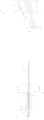
- FIG. 7 depicts a perspective cutaway view of the fitting 100 of FIGS. 4 - 6 in accordance with one embodiment prior to attachment of the collar 112 and seal body 110.
- FIG. 7 shows the fitting 100 after attachment of the inner tube 120 and the tube sleeve 114 via a welding process.
- the inner tube 120 and the tube sleeve 114 may first be aligned at the ends thereof.
- a circumferential weld 182 may be applied at the endface created by each of the front endface 132 of the tube sleeve 114 and the first end 172 of the inner tube 120.
- the weld 182 may be particularly located at the endface of the tube assembly 114, 120.
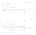
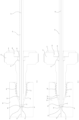
- FIG. 8 depicts a side cross sectional view of the fitting 100 of FIGS. 4-7 attached to a receiver 200 before tightening in accordance with one embodiment.
- FIG. 9 depicts a side cross sectional view of the fitting 100 of FIGS. 4-7 attached to the receiver 200 after tightening in accordance with one embodiment.
- the receiver 200 may be a female receiver fitting, or any other type of fitting configured to connect, mate or create a fluidic coupling with a male fitting such as the fitting 100.
- the female receiver 200 is shown including a threaded bore 218 extending from an opening end.
- a tapered bore 216 extends from the threaded bore 218 deeper into the receiver 200.
- An inner bore 213 extends from the tapered bore 216 to a sealing surface 214.
- a channel 210 extends from the sealing surface 214 through which fluid from the fitting 100 is configured to be transported.
- the tapered surface 138 of the fitting 100 is shown aligned with the tapered bore 216 of the receiver 200 while the second endface 124 of the seal body 110 abuts the sealing surface 214 of the receiver 200.
- the seal body 110 is configured to deform over the second end 150 of the collar 112, as depicted with an expanded circumferential portion 184.
- a method of manufacturing the fitting 100 may include welding a tube sleeve, such as the tube sleeve 114, and an inner tube, such as the inner tube 120, at an endface of each of the tube sleeve and the inner tube, such as the front endface 132 and the first end 172, to create a tube assembly having a welded tube assembly endface, such as the polished surface 180.
- Method of manufacturing may also include polishing the welded tube assembly endface after the welding of the ends of the tube sleeve and the inner tube.
- FIG. 10 depicts an exploded perspective view of another exemplary fitting 300 in accordance with one embodiment.
- FIG. 11 depicts a side cross sectional view of the fitting of FIG. 10 in accordance with one embodiment.
- the fitting 300 may be deployed in the manner described in FIGS. 1 - 3 in a liquid chromatography system or any chromatography system.
- the fitting 300 may be is configured to connect to various liquid chromatography systems, such as 6 kilopounds per square inch (ksi) systems, 10 ksi systems, and/or 20 ksi systems. Similar to the fitting 100, the fitting 300 may be a tool-free fitting that eliminates the need for installation tools and can be sufficiently tightened by hand.
- the fitting 300 may be configured to eliminate debris from galling during tightening.
- the fitting 300 may further be configured to eliminate pinch points within a female receiver fitting and minimize seal creep and further eliminate dead volume.
- the fitting 300 may be configured for multiple installations and tightening sequences without compromising connection integrity.
- the fitting 300 is shown including a compression screw 310, a push ring 312, a retainer cap 314, a seal body 316 and a tube 318. Unlike the fitting 100, the fitting 300 does not include a tube sleeve, but rather includes only the single tube 318.
- the compression screw 310 is a first counterbore 334 extending from the back end 322 having a first circumference.
- the first counterbore 334 extends to a first seating surface 335.
- a second counterbore 336 extends from the first counterbore 334 further from the back end 322 having a second circumference that is less than the first circumference.
- the second counterbore 336 extends to a second seating surface 337.
- the second counterbore 336 may be configured to receive the push ring 312 with a clearance fit that allows the compression screw 310 to freely rotate about the push ring 312.
- the first counterbore 334 may be configured to receive a portion of the retainer cap 314 with an interference or press fit attachment so that rotation of the compression screw 310 causes rotation of the retainer cap 314.
- the retainer cap 314 may be configured to be welded, adhered or otherwise permanently attached to the end of the compression screw 310.
- the compression screw 310 may be made of a gall resistant stainless steel material to prevent galling and prevent debris from being created by the friction between the compression screw 310 and a female receiver fitting, as shown in FIGS. 12 - 13 .
- embodiments contemplated may be made of any metallic material. Materials that are not gall resistant are also contemplated. Non-gall-resistant materials may be gold plated to reduce galling.
- the retainer cap 314 includes a main body 345 having a circumference that covers most or all of the surface area of the back end 322 of the compression screw 310.
- a retainer cap 314 includes a circumferential extended portion 346 extending from the main body 345 of the retainer cap 314.
- the circumferential extending portion 346 may a circumference that corresponds to the circumference of the first counterbore 334 of the compression screw 310.
- the circumferential extending portion 346 is configured to attach to the back end of the compression screw 310 within the first counterbore 334 in a press fit or interference fit arrangement.
- the circumferential extending portion 346 may further be attached to the compression screw 310 with an adhesive or weld if necessary.
- the tube 318 includes a body extending between a first end 356 and a second end 358 and having a channel 360 extending therethrough.
- the tube 318 may be any length appropriate for a liquid chromatography application.
- the tube 318 may be made of, for example, stainless steel.
- the inner and outer dimensions of the tube 318 may be .004 inches and .025 inches, respectively.
- various dimensions of the tube 318 may be provided depending on the type of liquid chromatography application and the pressures and volume flow rates under which the fitting 300 and tube 318 is configured to operate.
- the tube 318 may further include a counterbore 362 extending from the first end 356 to a seating surface 363.
- the outer surface of the seal body 316 may be dimensioned to fit within the counterbore 362 of the tube 318.
- the counterbore 362 may be a narrower or thinner portion of the wall of the tube 318 relative to the rest of the length of the tube 318 that extends from the seating surface 363 toward the first end 356. This narrow or thinner portion may be configured to receive the second endface 354 of the seal body in a press fit, friction fit, or interference fit relationship.
- the outer threads 328 of the compression screw 310 are engaged with the threads 218 of the receiver fitting 200. As shown in FIG. 13 , when the seal body 316 is placed under axial compression by the tightening of the compression screw 310 within the female receiver 200 via engagement of the threads 328, 218. This tightening creates an axial compression on the seal body 316, which is configured to deform over the first end 356 of the tube 318, as depicted with an expanded circumferential portion 365.
Landscapes
- Engineering & Computer Science (AREA)
- General Engineering & Computer Science (AREA)
- Mechanical Engineering (AREA)
- Physics & Mathematics (AREA)
- Health & Medical Sciences (AREA)
- Life Sciences & Earth Sciences (AREA)
- Chemical & Material Sciences (AREA)
- Analytical Chemistry (AREA)
- Biochemistry (AREA)
- General Health & Medical Sciences (AREA)
- General Physics & Mathematics (AREA)
- Immunology (AREA)
- Pathology (AREA)
- Treatment Of Liquids With Adsorbents In General (AREA)
- Joints With Pressure Members (AREA)
Applications Claiming Priority (3)
| Application Number | Priority Date | Filing Date | Title |
|---|---|---|---|
| US201962886375P | 2019-08-14 | 2019-08-14 | |
| PCT/US2020/045940 WO2021030439A1 (en) | 2019-08-14 | 2020-08-12 | Fitting for fluidic coupling in a chromatography system |
| EP20761952.9A EP4014036B1 (de) | 2019-08-14 | 2020-08-12 | Anschlussstück für fluidische kupplung in einem chromatografiesystem |
Related Parent Applications (1)
| Application Number | Title | Priority Date | Filing Date |
|---|---|---|---|
| EP20761952.9A Division EP4014036B1 (de) | 2019-08-14 | 2020-08-12 | Anschlussstück für fluidische kupplung in einem chromatografiesystem |
Publications (2)
| Publication Number | Publication Date |
|---|---|
| EP4534996A2 true EP4534996A2 (de) | 2025-04-09 |
| EP4534996A3 EP4534996A3 (de) | 2025-06-18 |
Family
ID=72243212
Family Applications (2)
| Application Number | Title | Priority Date | Filing Date |
|---|---|---|---|
| EP20761952.9A Active EP4014036B1 (de) | 2019-08-14 | 2020-08-12 | Anschlussstück für fluidische kupplung in einem chromatografiesystem |
| EP24218891.0A Pending EP4534996A3 (de) | 2019-08-14 | 2020-08-12 | Anschlussstück für fluidische kupplung in einem chromatografiesystem |
Family Applications Before (1)
| Application Number | Title | Priority Date | Filing Date |
|---|---|---|---|
| EP20761952.9A Active EP4014036B1 (de) | 2019-08-14 | 2020-08-12 | Anschlussstück für fluidische kupplung in einem chromatografiesystem |
Country Status (4)
| Country | Link |
|---|---|
| US (2) | US11782032B2 (de) |
| EP (2) | EP4014036B1 (de) |
| CN (2) | CN114303023B (de) |
| WO (1) | WO2021030439A1 (de) |
Families Citing this family (5)
| Publication number | Priority date | Publication date | Assignee | Title |
|---|---|---|---|---|
| KR20230154262A (ko) * | 2021-04-19 | 2023-11-07 | 가부시키가이샤 후지킨 | 조인트 |
| US12411114B2 (en) * | 2022-10-17 | 2025-09-09 | Agilent Technologies, Inc. | Chromatography column adaptor and use for fluidic connections |
| EP4677356A1 (de) | 2023-03-08 | 2026-01-14 | Waters Technologies Corporation | Chromatographiesäulenadapter mit gleitringdichtungen zur kopplung mit klemmenden fluidischen verbindern |
| EP4720656A1 (de) * | 2023-05-26 | 2026-04-08 | Waters Technologies Corporation | Einsatzdichtungsvorrichtung für eine chromatographiesäule |
| JP2025162168A (ja) * | 2024-04-15 | 2025-10-27 | 株式会社島津製作所 | 配管接続構造 |
Family Cites Families (75)
| Publication number | Priority date | Publication date | Assignee | Title |
|---|---|---|---|---|
| US2812959A (en) | 1953-08-21 | 1957-11-12 | Westinghouse Air Brake Co | Flange union fitting with gland expandible into an opening |
| US3141686A (en) | 1958-11-24 | 1964-07-21 | Smith Blair Inc | Pipe coupling |
| GB1233371A (de) | 1967-08-26 | 1971-05-26 | ||
| US4281679A (en) | 1979-08-27 | 1981-08-04 | Stearns Stanley D | Flow control means for use in an adaptor assembly |
| JPS59193351A (ja) * | 1983-04-18 | 1984-11-01 | Tokyo Rika Kikai Kk | 液体クロマトグラフの流路接続装置 |
| GB2184186A (en) | 1985-11-30 | 1987-06-17 | Tungum Hydraulics Ltd | Improvements in or relating to pipe couplings |
| US4690437A (en) | 1986-02-27 | 1987-09-01 | Alltech Associates, Inc. | Low pressure fitting |
| JP2645402B2 (ja) | 1987-09-11 | 1997-08-25 | 共伸工業株式会社 | 理化機器用パイプ接続装置 |
| GB2264543B (en) | 1992-02-19 | 1994-11-16 | Sergio Marius Julius Meli | Pipe fittings |
| US5423581A (en) | 1993-03-31 | 1995-06-13 | Salyers; Marshall L. | Low carryover fitting and method for coupling tubing to a device using the same |
| CA2478058C (en) * | 1993-03-31 | 2006-10-17 | Marshall L. Salyers | Low carryover fitting and method for coupling tubing to a device using the same |
| DE9320084U1 (de) | 1993-12-29 | 1995-04-27 | Gressel Ag, Aadorf | Rohrverschraubung in Stoßausführung |
| DE9405378U1 (de) | 1994-03-30 | 1994-06-23 | Hewlett-Packard GmbH, 71034 Böblingen | Trennsäule für die Chromatographie |
| US5669637A (en) | 1996-05-29 | 1997-09-23 | Optimize Technologies, Inc. | Miniature fitting assembly for micro-tubing |
| DE19755233C1 (de) | 1997-12-12 | 1999-04-29 | Festo Ag & Co | Einschraubteil |
| US6095572A (en) | 1998-01-20 | 2000-08-01 | Optimize Technologies, Inc. | Quarter turn quick connect fitting |
| US6273478B1 (en) | 1999-03-30 | 2001-08-14 | The Regents Of The University Of California | Microfluidic interconnects |
| US7467799B1 (en) | 1999-08-05 | 2008-12-23 | Oil States Industries, Inc. | Composite metal-to-metal seal having a relatively soft metal overlay and a relatively hard metal core |
| AUPQ646900A0 (en) | 2000-03-27 | 2000-04-20 | Sge International Pty Ltd | Metal ferrule for capillary tubing |
| JP2004537380A (ja) | 2001-08-08 | 2004-12-16 | ハイドロシジョン・インコーポレーテッド | 高圧迅速分離ハンドピースを備えた医療器具 |
| GB2407630B (en) | 2002-09-12 | 2007-05-02 | Waters Investments Ltd | Capillary interconnection fitting and method of holding capillary tubing |
| US7025360B2 (en) | 2002-09-25 | 2006-04-11 | Dril-Quip, Inc. | Metal seal with corrosion resistant alloy overlay |
| WO2004080564A1 (en) | 2003-03-07 | 2004-09-23 | Waters Investments Limited | Capillary tube liquid transport device |
| CA2466825C (en) | 2003-05-30 | 2011-04-19 | Hilti Aktiengesellschaft | Quick fastener |
| EP1635173B1 (de) | 2005-08-04 | 2008-02-27 | Agilent Technologies, Inc. | Kolonne mit konischem Zwischenstück |
| US7704388B2 (en) | 2006-01-31 | 2010-04-27 | Luknova, Inc | Reusable liquid chromatographic columns |
| EP2106547B1 (de) | 2007-01-09 | 2019-10-30 | Optimize Technologies, Inc. | Hochdruckanschlussteil |
| WO2009088663A1 (en) | 2008-01-02 | 2009-07-16 | Waters Technologies Corporation | Liquid-chromatography conduit assemblies having high-pressure seals |
| US20090188575A1 (en) | 2008-01-28 | 2009-07-30 | Colder Products Company | Quick Connect/Disconnect Coupling Assemblies |
| US8201854B2 (en) | 2008-06-02 | 2012-06-19 | Optimize Technologies, Inc. | Hybrid ferrule |
| DE102008059897B4 (de) * | 2008-12-02 | 2010-09-16 | Dionex Softron Gmbh | Steckereinheit und Verbindungssystem für das Verbinden von Kapillaren, insbesondere für die Hochleistungsflüssigkeitschromatographie |
| US20100224543A1 (en) | 2009-03-05 | 2010-09-09 | Ellis Scott J | Connection assembly for ultra high pressure liquid chromatography |
| US9151734B2 (en) | 2009-03-05 | 2015-10-06 | Idex Health & Science Llc | Connection assembly for ultra high pressure liquid chromatography |
| DE102009022368C5 (de) | 2009-05-22 | 2020-12-17 | Dionex Softron Gmbh | Steckereinheit und Verbindungssystem für das Verbinden von Kapillaren, insbesondere für die Hochleistungsflüssigkeitschromatographie |
| WO2011076244A1 (en) | 2009-12-21 | 2011-06-30 | Agilent Technologies, Inc. | Fitting element with front side seal |
| GB2477516A (en) | 2010-02-04 | 2011-08-10 | Agilent Technologies Inc | A seal for an HPLC column |
| KR20130105297A (ko) | 2010-04-30 | 2013-09-25 | 파커-한니핀 코포레이션 | 고압 튜브 피팅, 시일 및 단부면 마련 도구 |
| CN102971567B (zh) | 2010-05-03 | 2015-04-01 | 安捷伦科技有限公司 | 具有液压夹紧力元件的装配元件及相应的流体分离系统 |
| GB2527970B (en) | 2010-06-14 | 2016-02-10 | Agilent Technologies Inc | Fitting element with grip force distributor |
| US8569070B2 (en) | 2010-07-16 | 2013-10-29 | Idex Health & Science Llc | Connection assembly for ultra high pressure liquid chromatography |
| GB2482175B (en) | 2010-07-23 | 2016-01-13 | Agilent Technologies Inc | Fitting element with bio-compatible sealing |
| CN102537563B (zh) | 2010-12-28 | 2013-12-25 | 香港尚德-富佑捷有限公司 | 一种软管快速连接装置及其拆卸方法 |
| WO2012148793A1 (en) | 2011-04-25 | 2012-11-01 | Waters Technologies Corporation | Fitting assemblies |
| DE102011050037B3 (de) | 2011-05-02 | 2012-06-14 | Dionex Softron Gmbh | Steckereinheit und Verbindungssystem zum Verbinden von Kapillaren, insbesondere für die Hochleistungsflüssigkeitschromatographie |
| GB2491169B (en) | 2011-05-26 | 2014-09-10 | Thermo Electron Mfg Ltd | Method and apparatus for improved resolution chromatography |
| EP3584486A1 (de) | 2011-06-20 | 2019-12-25 | Waters Technologies Corporation | Hochdruckflüssigkeitsbuchse mit niedriger durchlässigkeit |
| CH705381B1 (de) * | 2011-08-15 | 2025-02-28 | Moeller Medical Gmbh | Rohr beinhaltend Metallmantel mit Kunststoff-Inlay zur Verwendung als Chromatographiesäule, insbesondere als HPLC-Säule |
| JP6021917B2 (ja) * | 2011-08-26 | 2016-11-09 | ウオーターズ・テクノロジーズ・コーポレイシヨン | 導管をポートへと取り付けるための再使用可能なフィッティング |
| DE102011082470A1 (de) | 2011-09-09 | 2013-03-14 | Agilent Technologies Inc. | Fitting mit lokaler Kapillarweitenanpassung |
| GB2499198A (en) | 2012-02-07 | 2013-08-14 | Agilent Technologies Inc | Fitting with microprotrusions for coupling capillary to chromatography column |
| WO2013173843A1 (en) | 2012-05-18 | 2013-11-21 | Optimize Technologies, Inc. | Fitting assembly |
| WO2013174421A1 (en) | 2012-05-22 | 2013-11-28 | Agilent Technologies, Inc. | Sealing element for a fluidic connection |
| CN104428665B (zh) | 2012-07-05 | 2017-07-07 | 安捷伦科技有限公司 | 具有底切锥形部的一件式套圈 |
| US10060560B2 (en) | 2012-07-17 | 2018-08-28 | Waters Technologies Corporation | High pressure fitting for supercritical fluid chromatography |
| DE102012108566B4 (de) | 2012-09-13 | 2016-01-28 | Dionex Softron Gmbh | Steckereinheit und Verbindungseinrichtung für Flüssigkeit führende Komponenten, insbesondere für die Hochleistungsflüssigkeitschromatographie |
| US9322811B2 (en) * | 2012-11-12 | 2016-04-26 | Dionex Corporation | Zero dead volume robust fluidic connection system |
| DE102012110991B4 (de) * | 2012-11-15 | 2017-01-05 | Dionex Softron Gmbh | Steckereinheit und Verbindungssystem zum Verbinden von Kapillaren, insbesondere für die Hochleistungsflüssigkeitschromatographie |
| US9482649B2 (en) | 2012-11-15 | 2016-11-01 | Agilent Technologies, Inc. | Fitting for elastically-biasing a capillary for a fluid-tight connection to a fluidic conduit |
| EP2741080A1 (de) | 2012-12-05 | 2014-06-11 | CTC Analytics AG | Vorrichtung sowie Verfahren zum Einspritzen eines Fluids in ein Analysegerät |
| US10385995B2 (en) * | 2012-12-20 | 2019-08-20 | Waters Technologies Corporation | Fluidic coupling seal |
| DE102014101759A1 (de) | 2014-02-12 | 2015-08-13 | Endress + Hauser Conducta Gesellschaft für Mess- und Regeltechnik mbH + Co. KG | Armatureinrichtung |
| WO2015160840A1 (en) | 2014-04-16 | 2015-10-22 | Idex Health & Science Llc | High pressure fluidic connection assemblies |
| EP3140583B1 (de) | 2014-05-07 | 2023-11-01 | Waters Technologies Corporation | Klemmverschraubung mit gekoppelter presshülse |
| US9764323B2 (en) | 2014-09-18 | 2017-09-19 | Waters Technologies Corporation | Device and methods using porous media in fluidic devices |
| WO2016065334A1 (en) * | 2014-10-23 | 2016-04-28 | Idex Health & Science Llc | Face-sealing fluidic connection system |
| US9671048B2 (en) * | 2014-10-23 | 2017-06-06 | Idex Health & Science Llc | Manifold connection assembly |
| US9950278B1 (en) | 2015-04-03 | 2018-04-24 | Yury Zelechonok | Chromatography column with inlet and outlet at one end |
| EP3163298B1 (de) * | 2015-10-30 | 2023-12-27 | Dionex Softron GmbH | Kapillarrohrverbindung |
| EP3244205A1 (de) | 2016-05-12 | 2017-11-15 | Möller Medical GmbH | Kapillaranschlusseinheit für analysegeräte und medizinische geräte |
| EP3258259B1 (de) | 2016-06-13 | 2025-10-22 | Dionex Softron GmbH | Kapillares verbindungssystem |
| WO2018017965A2 (en) * | 2016-07-21 | 2018-01-25 | Waters Technologies Corporation | Finger-tight high pressure fluidic coupling |
| US10514117B2 (en) * | 2016-10-05 | 2019-12-24 | Waters Technologies Corporation | Fluidic fitting with integral face seal |
| US10384151B2 (en) * | 2016-12-09 | 2019-08-20 | Idex Health & Science Llc | High pressure valve with two-piece stator assembly |
| DE102017129674A1 (de) * | 2017-12-12 | 2019-06-13 | Dionex Softron Gmbh | Steckereinheiten, insbesondere für HPLC, Verbindungssystem und entsprechende Verwendung |
| US11116150B2 (en) | 2018-07-09 | 2021-09-14 | The United States Of America, As Represented By The Secretary Of Agriculture | Aerial electrostatic system for weather modification |
-
2020
- 2020-08-12 EP EP20761952.9A patent/EP4014036B1/de active Active
- 2020-08-12 EP EP24218891.0A patent/EP4534996A3/de active Pending
- 2020-08-12 CN CN202080057487.0A patent/CN114303023B/zh active Active
- 2020-08-12 WO PCT/US2020/045940 patent/WO2021030439A1/en not_active Ceased
- 2020-08-12 CN CN202510027406.7A patent/CN119844633A/zh active Pending
- 2020-08-12 US US16/991,687 patent/US11782032B2/en active Active
-
2023
- 2023-10-05 US US18/481,380 patent/US12429463B2/en active Active
Also Published As
| Publication number | Publication date |
|---|---|
| US11782032B2 (en) | 2023-10-10 |
| EP4014036A1 (de) | 2022-06-22 |
| US20210048416A1 (en) | 2021-02-18 |
| US20240027408A1 (en) | 2024-01-25 |
| EP4014036B1 (de) | 2024-12-18 |
| CN119844633A (zh) | 2025-04-18 |
| EP4534996A3 (de) | 2025-06-18 |
| CN114303023A (zh) | 2022-04-08 |
| CN114303023B (zh) | 2025-01-17 |
| US12429463B2 (en) | 2025-09-30 |
| WO2021030439A1 (en) | 2021-02-18 |
Similar Documents
| Publication | Publication Date | Title |
|---|---|---|
| US12429463B2 (en) | Fitting for fluidic coupling in a chromatography system | |
| US4313828A (en) | High pressure tubing coupler | |
| US7909367B2 (en) | Capillary interconnection fitting and method of holding capillary tubing | |
| EP2593784B1 (de) | Verbindungsanordnung für ultrahochdruck-flüssigchromatografie | |
| US20170227507A1 (en) | Apparatus and method for coupling tubing to chromatographic column | |
| US20080309076A1 (en) | Device and Method for a Fluid-Tight Connection | |
| US10514117B2 (en) | Fluidic fitting with integral face seal | |
| EP3942294B1 (de) | Abnehmbare dichtungsvorrichtung für fluidische kupplung, fluidische kupplung und verfahren zur fluidischen kupplung | |
| US11986751B2 (en) | Seal for separation device | |
| US10385995B2 (en) | Fluidic coupling seal | |
| US20240393299A1 (en) | Insertion sealing device for a chromatography column | |
| US20150042089A1 (en) | High pressure fitting for a liquid chromatography system | |
| WO2005093256A1 (en) | A device having seal coatings for receiving and discharging fluid | |
| EP3469246B1 (de) | Fluidverbinderanordnung für schnellverbindung/schnelllösung |
Legal Events
| Date | Code | Title | Description |
|---|---|---|---|
| PUAI | Public reference made under article 153(3) epc to a published international application that has entered the european phase |
Free format text: ORIGINAL CODE: 0009012 |
|
| STAA | Information on the status of an ep patent application or granted ep patent |
Free format text: STATUS: THE APPLICATION HAS BEEN PUBLISHED |
|
| AC | Divisional application: reference to earlier application |
Ref document number: 4014036 Country of ref document: EP Kind code of ref document: P |
|
| AK | Designated contracting states |
Kind code of ref document: A2 Designated state(s): AL AT BE BG CH CY CZ DE DK EE ES FI FR GB GR HR HU IE IS IT LI LT LU LV MC MK MT NL NO PL PT RO RS SE SI SK SM TR |
|
| PUAL | Search report despatched |
Free format text: ORIGINAL CODE: 0009013 |
|
| AK | Designated contracting states |
Kind code of ref document: A3 Designated state(s): AL AT BE BG CH CY CZ DE DK EE ES FI FR GB GR HR HU IE IS IT LI LT LU LV MC MK MT NL NO PL PT RO RS SE SI SK SM TR |
|
| RIC1 | Information provided on ipc code assigned before grant |
Ipc: G01N 30/60 20060101AFI20250509BHEP |
|
| STAA | Information on the status of an ep patent application or granted ep patent |
Free format text: STATUS: REQUEST FOR EXAMINATION WAS MADE |
|
| 17P | Request for examination filed |
Effective date: 20251217 |