EP4535211A1 - Conversion d'une courbe de subdivision commandée par un maillage de base en un format de courbe de cao correspondant - Google Patents
Conversion d'une courbe de subdivision commandée par un maillage de base en un format de courbe de cao correspondant Download PDFInfo
- Publication number
- EP4535211A1 EP4535211A1 EP23306674.5A EP23306674A EP4535211A1 EP 4535211 A1 EP4535211 A1 EP 4535211A1 EP 23306674 A EP23306674 A EP 23306674A EP 4535211 A1 EP4535211 A1 EP 4535211A1
- Authority
- EP
- European Patent Office
- Prior art keywords
- curve
- cad
- subdivision
- base mesh
- bezier
- Prior art date
- Legal status (The legal status is an assumption and is not a legal conclusion. Google has not performed a legal analysis and makes no representation as to the accuracy of the status listed.)
- Pending
Links
Images


Classifications
-
- G—PHYSICS
- G06—COMPUTING OR CALCULATING; COUNTING
- G06F—ELECTRIC DIGITAL DATA PROCESSING
- G06F30/00—Computer-aided design [CAD]
- G06F30/10—Geometric CAD
- G06F30/12—Geometric CAD characterised by design entry means specially adapted for CAD, e.g. graphical user interfaces [GUI] specially adapted for CAD
-
- G—PHYSICS
- G06—COMPUTING OR CALCULATING; COUNTING
- G06F—ELECTRIC DIGITAL DATA PROCESSING
- G06F30/00—Computer-aided design [CAD]
- G06F30/10—Geometric CAD
- G06F30/15—Vehicle, aircraft or watercraft design
-
- G—PHYSICS
- G06—COMPUTING OR CALCULATING; COUNTING
- G06F—ELECTRIC DIGITAL DATA PROCESSING
- G06F30/00—Computer-aided design [CAD]
- G06F30/10—Geometric CAD
- G06F30/17—Mechanical parametric or variational design
-
- G—PHYSICS
- G06—COMPUTING OR CALCULATING; COUNTING
- G06F—ELECTRIC DIGITAL DATA PROCESSING
- G06F30/00—Computer-aided design [CAD]
- G06F30/20—Design optimisation, verification or simulation
- G06F30/23—Design optimisation, verification or simulation using finite element methods [FEM] or finite difference methods [FDM]
-
- G—PHYSICS
- G06—COMPUTING OR CALCULATING; COUNTING
- G06T—IMAGE DATA PROCESSING OR GENERATION, IN GENERAL
- G06T17/00—Three-dimensional [3D] modelling for computer graphics
- G06T17/20—Finite element generation, e.g. wire-frame surface description, tesselation
-
- G—PHYSICS
- G06—COMPUTING OR CALCULATING; COUNTING
- G06T—IMAGE DATA PROCESSING OR GENERATION, IN GENERAL
- G06T17/00—Three-dimensional [3D] modelling for computer graphics
- G06T17/30—Polynomial surface description
-
- G—PHYSICS
- G06—COMPUTING OR CALCULATING; COUNTING
- G06F—ELECTRIC DIGITAL DATA PROCESSING
- G06F2111/00—Details relating to CAD techniques
- G06F2111/04—Constraint-based CAD
-
- G—PHYSICS
- G06—COMPUTING OR CALCULATING; COUNTING
- G06F—ELECTRIC DIGITAL DATA PROCESSING
- G06F2119/00—Details relating to the type or aim of the analysis or the optimisation
- G06F2119/18—Manufacturability analysis or optimisation for manufacturability
Definitions
- the disclosure relates to the field of computer programs and systems, and more specifically to a method, system and program for converting a subdivision curve controlled by a base mesh into a corresponding CAD curve format.
- CAD Computer-Aided Design
- CAE Computer-Aided Engineering
- CAM Computer-Aided Manufacturing
- the graphical user interface plays an important role as regards the efficiency of the technique.
- PLM refers to an engineering strategy that helps companies to share product data, apply common processes, and leverage corporate knowledge for the development of products from conception to the end of their life, across the concept of extended enterprise.
- the PLM solutions provided by Dassault Systèmes (under the trademarks CATIA, SIMULIA, DELMIA and ENOVIA) provide an Engineering Hub, which organizes product engineering knowledge, a Manufacturing Hub, which manages manufacturing engineering knowledge, and an Enterprise Hub which enables enterprise integrations and connections into both the Engineering and Manufacturing Hubs. All together the solutions deliver common models linking products, processes, resources to enable dynamic, knowledge-based product creation and decision support that drives optimized product definition, manufacturing preparation, production and service.
- Computer-aided design of a product to be manufactured may typically involve several stages.
- Class A modeling is a late stage of such process, for example the last stage before the model enters the computer-aided manufacturing (CAM) phase.
- Class A modeling uses CAD models (of products) that feature quality surfaces. That is, the CAD model, for example B-rep model, has an outer surface representing the outer surface portion of the product, and this outer surface has quality (general G2 continuity, also referred to as curvature continuity).
- the CAD model may be in condition for a downstream manufacturing phase. That is, the model may be stored in or as a CAD file which may be then used in the CAM phase, for manufacturing.
- the surfaces of the model have sufficient quality for manufacturing and can thereby be manufactured by the appropriate machines. For example, such quality surfaces allow manufacturing by continuous application of a machining tool.
- Class A surface may be created from curves using well known CAD features, such as fill, sweep, loft, net, extrusion and others. These curves are thus used to create surfaces and control them afterwards (i.e. once created). In modern CAD tools for Class A modeling, these curves comprise Bezier or NURBS curves, which allow the creation of tense curves with quality curvatures (G2 continuity). These curves give an ergonomic access to the surface, like a handle to create & deform the shapes. In Class A, quality of the curve is key, as leading to a quality surface.
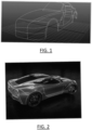
- FIG.s 1 and 2 show examples a screenshots of Class A CAD models of cars each with an outer surface comprised of several quality surfaces defined by such quality curves.
- complex curves may be created using several G2 connected Bezier curves.
- Each Bezier curve may typically be limited to an 11-15 order to avoid instability issues.
- NURBS curves with a high segmentation may be used. Bezier curves are known to provide a high-quality resulting shape.
- a single Bezier curve however limits the complexity of the shape (whereas the design may be complex due to manufacturing and/or mechanical constraints), such that in practice several Bezier curves must be connected to create complex shapes, thereby leading to numerous steps to generate clear surfaces.
- connections between Bezier curves need to be always checked by the user or guaranteed by the CAD system through constraints. This implies additional steps (user editions and/or computer calculations for enforcing constraints) and/or additional user-provided knowledge. This deteriorates ergonomics, speed, and efficiency (including computer efficiency) of the design process.
- FIG. 3 shows examples of Bezier curves
- FIG. 4 examples of G2-connected Bezier curves.
- NURBS curves allow the creation of more complex shapes, but the possible complexity is however still too limited. Furthermore, manipulating arcs limits of NURBS can have a big influence very far on the curve. This implies that manipulating a part of the design through NURBS arc limit manipulation may impact another part of the design defined by the same NURBS curve, whereas this other part was not intended to me modified. This results in a lack of ergonomy, as many interactions are needed to perform the intended editions and correct the unintended editions, and/or very precise interactions are needed to perform editions that do not result in unintended modifications (this would require great hand precision and/or great high focus, thereby causing a great physiological burden on the designer).
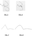
- FIG. 5 shows a screenshot of a NURBS curve.
- Cursor 50 is placed on a control point and moved by the user, so as to move the control point to perform an edition.
- FIG. 6 shows the result of the move of the cursor 50, and as can be seen on FIG. 6 , the move has unintendedly strongly modified parts of the curve which are located far away.
- a computer-implemented method for converting a subdivision curve into a corresponding computer-aided design (CAD) curve format The subdivision curve is controlled by a base mesh.
- the base mesh is formed by vertices connected by one or more edges.
- the subdivision curve defines at least a part of a product to be manufactured.
- the method is for designing the product.
- the method comprises transforming the subdivision curve into a G2-continous CAD curve.
- the CAD curve is formed by the union of one or more Bezier curves. Each Bezier curve corresponds to a respective edge of the base mesh.
- a control polygon of the CAD curve is computed from the base mesh ( i.e . the CAD curve has a control polygon computed from the base mesh).
- the transformation is based on a Catmull-Clark refinement process.
- the method may be referred to as "the conversion method”.
- the conversion method may comprise one or more of the following:
- a system comprising a processor coupled to a memory, the memory having recorded thereon the computer program and/or the CAD model.
- a device comprising a data storage medium having recorded thereon the computer program and/or CAD model.
- a computer-implemented method for converting a subdivision curve into a corresponding computer-aided design (CAD) curve format The subdivision curve is controlled by a base mesh.
- the base mesh is formed by vertices connected by one or more edges.
- the subdivision curve defines at least a part of a product to be manufactured.
- the method is for designing the product.
- the method comprises transforming the subdivision curve into a G2-continous CAD curve.
- the CAD curve is formed by the union of one or more Bezier curves. Each Bezier curve corresponds to a respective edge of the base mesh.
- a control polygon of the CAD curve is computed from the base mesh.
- the transformation is based on a Catmull-Clark refinement process.
- the method may be referred to as "the conversion method", as previously discussed.
- the conversion method is for designing the product to be manufactured of which at least a part is defined by the input subdivision curve.
- This means that the result of the conversion method is usable for designing the product, for example usable in step that is part of the process of design of this product.
- This step may consist in the method of use, also referred to as "the design method".
- the conversion method and the design method may be integrated into a same design process, which comprises performing the conversion method and then the design method.
- the conversion method itself may form a design step, for example if it comprises, by the user, creating the input subdivision curve by performing a sketch of the geometrical shape of the curve. Then, upon creation of the sketch, the method may comprise, automatically by the system, the calculation of the base mesh and then the conversion into the CAD format.
- the product is to be manufactured. This means that at some point after the method, that is downstream to the method, after execution of the design method for example, a model of the product resulting from the design and comprising said part defined by the subdivision curve will be used for manufacturing the product in accordance with the design.
- the input of the method is the subdivision curve.
- the subdivision curve is defined by a base mesh.
- the base mesh fully defines the subdivision curve.
- the base mesh may reflect and control a geometrical shape of the curve. Creation of the subdivision curve may comprise, by a user, defining the geometrical shape (for example by performing a shape), and, by the computer system, automatic inference of the base mesh by any suitable method.
- the base mesh is a topological structure that consists in a set of vertices and edges, each edge connecting two vertices.
- the base mesh comprises one or more of such edges.
- the vertices and the edges may be referred to as cells. This topological structure controls and defines the geometrical shape of the curve.
- a subdivision curve is equal to the boundary of a subdivision surface where the base mesh of the subdivision surface is the extrusion of the base mesh of the subdivision curve.
- FIG.s 7 to 10 illustrate this bridge between subdivision curves and surfaces.
- FIG. 8 shows a subdivision curve and FIG. 7 shows its base mesh.
- FIG. 9 shows the base mesh of the corresponding subdivision surface, which as can be seen is the extrusion of the base mesh shown on FIG. 7 .
- FIG. 10 shows the subdivision surface, which is the extrusion of the subdivision curve shown on FIG. 8 .
- the subdivision curve shown in FIG. 7 is a boundary of the subdivision surface shown in FIG. 9
- the subdivision curve shown on FIG. 8 is a boundary of the subdivision surface shown on FIG. 10 .
- the subdivision curve defines at least a part of the product to be manufactured.
- the product as modeled in the CAD system, has a part (e.g . an outer surface portion) defined based on the subdivision curve.
- the outer surface portion may be the CAD curve into which the subdivision curve is converted, or a surface extruded from this CAD curve. This does however not exclude further design steps where this part of the CAD model of the product defined by the subdivision curve is modified.
- the method may comprise, for example as an initial step, providing (obtaining) the subdivision curve.
- Providing the subdivision curve may comprise creating the subdivision curve.
- Creating the subdivision curve may comprise sketching, by graphical user interaction, a geometrical shape of the curve, and then, by the computer system, automatically computing the base mesh (by any suitable method).
- the creation may optionally comprise further modification(s), by graphical user interaction, of the base mesh.
- Providing the subdivision curve may alternatively comprise retrieving ( e.g . downloading) the curve from a ( e.g . distant) data storage medium where the subdivision curve has been stored further to its creation.
- the method comprises (for example further to the providing of the subdivision curve) transforming the subdivision curve into a G2-continous CAD curve formed by the union of one or more Bezier curves.
- This step may be performed automatically by the computer system, that is without any further user action (e.g. without for example the user having to click on a button to launch the transformation), upon the providing of the subdivision curve.
- the user may create the subdivision curve's geometrical shape as explained above, upon which the computer system automatically computes the base mesh and automatically performs the transforming step.
- This may be performed in real-time, i.e. the time between the providing of the subdivision curve and the result of the transforming step may be of a few seconds or less, for example lower than 10s, 5s, 2s or 1s.
- the method may comprise displaying the G2-continous curve on a display of the computer system. This provides instantaneous visual feedback to the user, which for example upon sketching the shape of the subdivision curve is automatically and in real-time provided with visual feedback in the form of the display of the G2-continous curve resulting from the transforming step.
- the method may also comprise displaying the base curve, for example by default as of its creation and for the remaining part of the method (including the transforming step), and/or displaying the control polygon of each Bezier curve, for example by default once the transforming step is done.
- the display of the base curve and/or of the control polygons of the Bezier curves may be performed upon the user activating a display graphical command (for example by clicking on a button).
- the user may for example trigger the display of the base curve by a specific graphical command activation and/or the display of the control polygons of all the Bezier curves or of one or more of them by another specific graphical command activation.
- the transforming step may also be referred to as "the conversion step”.
- This transforming/conversion step is done by applying a conversion process that is based on a Catmull-Clark refinement process, for example by using applying directly a Catmull-Clark refinement process.
- the Catmull-Clark refinement process works as follows. Given a curve base mesh, the process performs a subdivision that iteratively refines the base mesh ( i.e . by iteratively adding vertices and/or edges). This process converges to a limit curve, that is a uniform cubic spline.
- the spline may be C2-continuous when the subdivision curve does not comprise sharpness or weight.
- FIG.s 11, 12A and 13 illustrate such a process.
- FIG. 11 shows a base mesh 110 and the limit curve 112.
- FIG. 12A further shows the result 120 of the first subdivision level.
- FIG. 13 further shows the result 130 of the second subdivision level.
- the curve that results from the conversion is a G2-continuous curve which is a uniform cubic spline (as discussed in reference Catmull, "A Subdivision Algorithm for Computer Display of Curved Surfaces", PhD thesis 1974 , which is incorporated herein by reference).
- This G2 continuous curve is formed by the union of the one or more Bezier curves, each resulting from the conversion of a respective base mesh edge.
- curvature refers to a geometry term indicating the extent that a curve or surface deviates from perfect straightness or flatness. Curvature may be measured as the inverse of a local osculating radius. Thus, a curve has a low curvature and a large radius when it is slightly bent only and has a high curvature and a small radius if bent sharply.
- Continuity refers herein to a connection type at a given point.
- G0 continuity stands for point continuity at the point (meaning that the curve is continuous at the point)
- G1 continuity stands for tangent continuity (meaning that the tangent of the curve is continuous at the point)
- G2 continuity stands for curvature continuity (meaning that the curvature of the curve is continuous at the point).
- a curve is G0-continous (resp. G1-continuous, resp G2-continuous) if it has G0 continuity (resp. G1 continuity, resp. G2 continuity) in all its points.
- G0 continuity is commonly used to represent crease/sharp features.
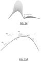
- FIG. 14 illustrates the concept of G0 continuity.
- the curve base mesh is the control polygon of the generated cubic B-spline curve, which is the union of N Bezier curves, N being the number of edges of the base mesh.
- Each Bezier curve may be associated with a control polygon (i.e. its own respective control polygon).
- the concept of control polygon of (or associated with) a Bezier or NURBS curve is well known.
- This control polygon associated with the Bezier curve has control points which may depend linearly on vertices of the base mesh.
- the control points of the control polygon associated with the Bezier curve may correspond to a product of said vertices of the base mesh with a matrix.
- Said vertices of the base mesh may include the vertices connected by the respective edge to which the Bezier curve corresponds and vertices of neighboring edges (for example the vertices of all the base mesh edges that include at least one vertex of said respective edge).
- FIG. 15A shows the spline 154, the base mesh 150 which is the control polygon of the spline 154, and the control polygon 152 which is that of the Bezier curve associated with edge P2-P3 of the base mesh 150 (Pi being the vertices of the base mesh, and Qi the control points of the control polygons of the Bezier curves).
- edge P2-P3 in FIG. 15A Although the formula is illustrated by edge P2-P3 in FIG. 15A , the corresponding same formula is used for the other edges.
- Valence is the number of edges around a vertex of the base mesh.
- the valence can be 1 (for extremity vertices) or 2 (for internal vertices), for surfaces valence is at least 2.
- the term "extraordinary vertex" comes from the Subdivision Surface literature to qualify types of base mesh vertices.
- vertices are said regular if they don't have any weight or sharpness and if they're internal with valence 4 or on the boundary with valence 2 or 3. They are called extraordinary otherwise.
- surfaces meet with natural C2 continuity.
- an extraordinary vertex surfaces meet with G0 or G1 continuity only.
- regular vertices are all vertices without sharpness or weight.
- the matrix may be such that it enables sharpness preservation in the Bezier curve.
- Q1 depends on P1, P2, P3.
- P2 is sharp
- the matrix may be modified so that Q1 only depends on P2 and P3. This may be applied equally to each such sharp vertex.
- the matrix may be such that it enables weight preservation in the Bezier curve.
- a specific treatment may be done to the matrix to ensure a good curvature around P2.
- This process may be any process suitable for this purpose, for example that which is partially expressed in EP Patent Application Publication EP1750228A2 (which has been granted), which is incorporated herein by reference. More specifically, in the case of subdivision surfaces, previously mentioned EP Patent Application Publication EP1750228A2 describes how to improve the shape of the approximated surface around extraordinary vertices.
- the process may add more degrees of freedom by using NURBS curve (e.g. degree 6 NURBS curve in implementations).
- NURBS curve e.g. degree 6 NURBS curve in implementations.
- the extra control points required to define this curve may be moved by solving a linear system, optimizing the shape curvature quality, as disclosed in paragraphs [0033] to [0037], [0068] to [0077] and FIG. 3 of EP Patent Application Publication EP1750228A2 .
- the method may use this disclosure to compute an approximation of a subdivision curve which is the restriction of a subdivision surface when there is at least one extraordinary vertex.
- the method may comprise defining for each edge with at least one extraordinary vertex a local subdivision surface base mesh on which the method computes the subdivision surface, using the disclosure of EP Patent Application Publication EP1750228A2 and extracts the appropriate boundary, which forms the approximation of the subdivision curve.
- the control polygon in this case may be that of the approximation of the subdivision curve.
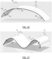
- This surface base mesh is simply the extrusion in any direction of the one of the curves, with weights and sharpness also reported. This is illustrated on FIG.s 15B and 15C , where FIG. 15B shows the curve approximation in the extraordinary case where vertex P2 of edge P2P3 has weight, and FIG. 15C illustrates the subdivision surface mesh creation and boundary curve extraction.
- Subdivision curves come with a multi-level description that allows the user to access to a base-mesh.
- This base-mesh is similar to a control points network for a Bezier curve but behaves much more globally. Thanks to this mathematical description, it becomes very easy to create very complex curves, keeping a very simple base-mesh.
- attraction weight
- This attraction can be put onto vertices & edges, to deform the resulting curve without modification on the vertex position of the base-mesh, offering even more freedom.
- This attraction can be a sharp one, allowing the user to create a curve which is natively G2 continuous, and punctually only G0, to create sharp vertices, or polylines, or other sharp features.
- subdivision curve topology is completely free. It is thus very easy to create an opened curve, but also a closed curve, with any kind of shape.
- the conversion method also offers a native bridge between the curve world and the surface world.
- subdivision surfaces are mainly used for modeling, it becomes much easier to create subdivision surfaces from subdivision curves, bringing also better and more precise result (with less or without deviation).
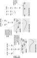
- FIG. 23 illustrate a circular closed shape 230 defined by a base mesh 232 formed by 4 vertices. Such a shape could not be created using standard Bezier and NURBS curve. Shape deformation can be easily performed by adding a vertex to the base mesh 232 (as shown on FIG. 24 ) and opening the shape can be easily done by removing an edge of the base mesh 232 (as shown on FIG. 25).
- FIG. 26 shows that a bevel with 3 vertices can be easily created (here on the bottom left vertex of base mesh 232) to create pinch, like a fillet.
- the at least a part is obtainable according to the conversion of the base mesh of the subdivision curve into a corresponding CAD curve format, where the conversion is according to the conversion method, and the at least a part corresponds to a G2-continous CAD curve formed by the union of one or more Bezier curves.
- This means that the at least a part is, or is obtained from, the G2-continous CAD curve, and that this G2-continous CAD curve is the G2-continous CAD curve that results from the transforming step of the conversion method applied to the subdivision curve that defined the at least a curve, or any G2-continous CAD curve that could have been obtained by applying the conversion method to the subdivision curve.
- this G2-continuous CAD curve is formed by the union of one or more Bezier curves, the number of Bezier curves is equal to the number of edges of a base mesh of the subdivision curve, and the base mesh forms a control polygon of the CAD curve, as it is for the conversion method.
- the subdivision curve and the G2-continous CAD curve to which the at least a part of the model corresponds may have anyone or any combination of the features of those curves as described for the conversion method.
- corresponds to it is meant that the at least a part may be the G2-continous CAD curve or may be obtained therefrom.
- the at least a part may be a surface resulting from the extrusion of the G2-continous CAD curve.
- the method of use comprises performing one or more modifications of the base mesh of the subdivision curve.
- the one or more modifications are passed (automatically by the computer, for example using the relation linking the control polygons of the Bezier curves and the base mesh) on said at least a part of the CAD model.
- the method of use comprises applying one or more CAD operations to said at least a part.
- Performing one or more modifications of the base mesh of the subdivision curve may include performing one or more of:
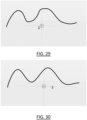
- FIG.s 29 to 38 show screenshots of a video of a designer using subdivision curves according to an implementation of the methods. These figures illustrate the methods and advantages thereof.
- FIG. 29 shows a screenshot of a shape of a subdivision curve that the designer has just created. The conversion method is being applied, and a few seconds later, the subdivision curve has been converted into the CAD curve format by the conversion method.
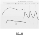
- FIG. 30 shows this G2-continuous CAD curve.
- FIG. 31 shows several G2-continuous CAD curves, including that of FIG. 30 , obtained in the same way.
- FIG. 32 shows the display of the respective base meshes of the input subdivision curves. This display may be triggered upon the user activating a command for that purpose.
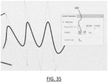
- FIG. 33 shows a screenshot of a graphical widget for modifying a base mesh.
- This graphical widget is actually displayed on a same screen as the curves shown in the previous figures 29 to 32 but is shown separately in the present disclosure for clarity.
- the widget allows the user to, upon selection of a base mesh (or several), modify parameters of the base mesh(es), including its (their) complexity (number of vertices).
- the graphical widget may be displayed upon the user activating a command for that purpose.
- the user has just modified the number of vertices from 8 to 5 for the bottom curve shown on FIG.s 31-32 .
- FIG. 34 shows the result of this modification on the bottom curve.
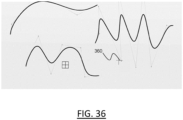
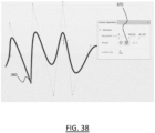
- FIG. 35 shows a partial screenshot of still the same screen, where yet another widget has been displayed upon user-activation of a command for that purpose.
- the user has selected (clicked on) a graphical tool 350 that allows modification of the weight of a selected mesh vertex (or more).
- FIG. 36 it is shown that the user has selected vertex 360 of the right-side curve's base mesh.
- FIG. 37 shows, the widget of FIG. 35 being displayed along the right-side curve, the user interacting with the widget to modify the weight value of the selected vertex 360 to 76%, thereby modifying the shape of the curve.
- FIG. 38 shows yet another interaction of the user with the displayed widget, where the user has selected this time the sharpness graphical tool 370, thereby making the selected vertex 360 sharp.
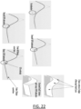
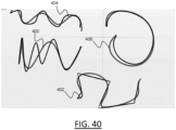
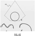
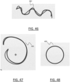
- FIG.s 39 to 48 are screenshots from the same CAD software interface as that shown in FIG.s 29 to 38 and illustrate a comparison between subdivision curves and Bezier curves.
- FIG. 39 shows five subdivision curves.
- Bezier curves 400, 402, 404, 406 and 408 have been sketched over the subdivision curves of FIG. 39 to roughly reproduce their shapes.
- FIG.s 42 to 45 show the control polygons 420, 428, 422 and 426 of, respectively, Bezier curves 400, 408, 402 and 402.
- the polygons do not fit well the curves due to the complex shapes of these curves, and are not at all ergonomics to manipulate, as they stretch wide and far over the screen.
- FIG.s 46 to 48 show the base meshes 460, 466 and 468 of curves 400, 406 and 408 (respectively). As can be seen, these base meshes fit much better the shapes of the curves and are clearly more ergonomic to manipulate.
- Designing a manufacturing product (or product to be manufactured)/mechanical part/mechanical product designates any action or series of actions which is at least a part of a process of elaborating a modeled object (3D or 2D) of the manufacturing product/mechanical part/mechanical product.
- the conversion method and/or the method of use may be part of such process, as previously explained.
- the methods thus generally manipulate modeled objects, such as the subdivision curve, the CAD model, of the CAD curve format discussed herein.
- a modeled object is any object defined by data stored e.g. in the database.
- the expression "modeled object" designates the data itself.
- the modeled objects may be defined by different kinds of data.
- the system may indeed be any combination of a CAD system, a CAE system, a CAM system, a PDM system and/or a PLM system.
- modeled objects are defined by corresponding data.
- CAD solution e.g. a CAD system or a CAD software
- CAD solution any system, software or hardware, adapted at least for designing a modeled object on the basis of a graphical representation of the modeled object and/or on a structured representation thereof (e.g. a feature tree), such as CATIA.
- the data defining a modeled object comprise data allowing the representation of the modeled object.
- a CAD system may for example provide a representation of CAD modeled objects using edges or lines, in certain cases with faces or surfaces. Lines, edges, or surfaces may be represented in various manners, e.g. non-uniform rational B-splines (NURBS).
- NURBS non-uniform rational B-splines
- a CAD file contains specifications, from which geometry may be generated, which in turn allows for a representation to be generated. Specifications of a modeled object may be stored in a single CAD file or multiple ones.
- the typical size of a file representing a modeled object in a CAD system is in the range of one Megabyte per part.
- a modeled object may typically be an assembly of thousands of parts.
- a modeled object may typically be a 2D or 3D modeled object, e.g. representing a product such as a part or an assembly of parts, or possibly an assembly of products.
- the 2D or 3D modeled object may be a manufacturing product, i.e. a product to be manufactured.
- 3D modeled object it is meant any object which is modeled by data allowing its 3D representation.
- a 3D representation allows the viewing of the part from all angles.
- a 3D modeled object when 3D represented, may be handled and turned around any of its axes, or around any axis in the screen on which the representation is displayed. This notably excludes 2D icons, which are not 3D modeled.
- the display of a 3D representation facilitates design (i.e. increases the speed at which designers statistically accomplish their task). This speeds up the manufacturing process in the industry, as the design of the products is part of the manufacturing process.
- the 2D or 3D modeled object may represent the geometry of a product to be manufactured in the real world subsequent to the completion of its virtual design with for instance a CAD/CAE software solution or CAD/CAE system, such as a (e.g. mechanical) part or assembly of parts (or equivalently an assembly of parts, as the assembly of parts may be seen as a part itself from the point of view of the method, or the method may be applied independently to each part of the assembly), or more generally any rigid body assembly (e.g. a mobile mechanism).
- a CAD/CAE software solution allows the design of products in various and unlimited industrial fields, including: aerospace, architecture, construction, consumer goods, high-tech devices, industrial equipment, transportation, marine, and/or offshore oil/gas production or transportation.
- the 3D modeled object designed by the method may thus represent an industrial product which may be any mechanical part, such as a part of a terrestrial vehicle (including e.g. car and light truck equipment, racing cars, motorcycles, truck and motor equipment, trucks and buses, trains), a part of an aerial vehicle (including e.g. airframe equipment, aerospace equipment, propulsion equipment, defense products, airline equipment, space equipment), a part of a naval vehicle (including e.g. navy equipment, commercial ships, offshore equipment, yachts and workboats, marine equipment), a general mechanical part (including e.g. industrial manufacturing machinery, heavy mobile machinery or equipment, installed equipment, industrial equipment product, fabricated metal product, tire manufacturing product), an electro-mechanical or electronic part (including e.g.
- a terrestrial vehicle including e.g. car and light truck equipment, racing cars, motorcycles, truck and motor equipment, trucks and buses, trains
- an aerial vehicle including e.g. airframe equipment, aerospace equipment, propulsion equipment, defense products, airline equipment, space equipment
- a consumer good including e.g. furniture, home and garden products, leisure goods, fashion products, hard goods retailers' products, soft goods retailers' products
- a packaging including e.g. food and beverage and tobacco, beauty and personal care, household product packaging.
- a CAD system may be history-based.
- a modeled object is further defined by data comprising a history of geometrical features.
- a modeled object may indeed be designed by a physical person (i.e. the designer/user) using standard modeling features (e.g. extrude, revolute, cut, and/or round) and/or standard surfacing features (e.g. sweep, blend, loft, fill, deform, and/or smoothing).
- standard modeling features e.g. extrude, revolute, cut, and/or round
- standard surfacing features e.g. sweep, blend, loft, fill, deform, and/or smoothing.
- Many CAD systems supporting such modeling functions are history-based system. This means that the creation history of design features is typically saved through an acyclic data flow linking the said geometrical features together through input and output links.
- the history based modeling paradigm is well known since the beginning of the 80's.
- a modeled object is described by two persistent data representations: history and B-rep (i.e. boundary representation).
- the B-rep is the result of the computations defined in the history.
- the shape of the part displayed on the screen of the computer when the modeled object is represented is (e.g. a tessellation of) the B-rep.
- the history of the part is the design intent. Basically, the history gathers the information on the operations which the modeled object has undergone.
- the B-rep may be saved together with the history, to make it easier to display complex parts.
- the history may be saved together with the B-rep in order to allow design changes of the part according to the design intent.
- PLM system it is additionally meant any system adapted for the management of a modeled object representing a physical manufactured product (or product to be manufactured).
- a modeled object is thus defined by data suitable for the manufacturing of a physical object. These may typically be dimension values and/or tolerance values. For a correct manufacturing of an object, it is indeed better to have such values.
- CAE solution it is additionally meant any solution, software of hardware, adapted for the analysis of the physical behavior of a modeled object.
- a well-known and widely used CAE technique is the Finite Element Model (FEM) which is equivalently referred to as CAE model hereinafter.
- FEM Finite Element Model
- An FEM typically involves a division of a modeled object into elements, i.e., a finite element mesh, which physical behaviors can be computed and simulated through equations.
- Such CAE solutions are provided by Dassault Systdiags under the trademark SIMULIA ® .
- Another growing CAE technique involves the modeling and analysis of complex systems composed a plurality of components from different fields of physics without CAD geometry data. CAE solutions allow the simulation and thus the optimization, the improvement and the validation of products to manufacture.
- CAE solutions are provided by Dassault Systèmes under the trademark DYMOLA ® .
- CAE may be used to ensure that various structural requirements (such as, but not limited to, mass, stiffness, strength, durability) are achieved by a new CAD model. Some of these requirements may be called Key Performance Indicators (KPIs). For many industrial products (for example cars, airplanes, consumer packaged goods, hi-tech), these KPIs are in conflict e.g. lower mass usually causes lower stiffness. Thus, optimization methods are often applied to find the best trade-off between the KPls.
- KPIs Key Performance Indicators
- CAM solution it is meant any solution, software of hardware, adapted for managing the manufacturing data of a product.
- the manufacturing data generally include data related to the product to manufacture, the manufacturing process and the required resources.
- a CAM solution is used to plan and optimize the whole manufacturing process of a product. For instance, it may provide the CAM users with information on the feasibility, the duration of a manufacturing process or the number of resources, such as specific robots, that may be used at a specific step of the manufacturing process; and thus, allowing decision on management or required investment.
- CAM is a subsequent process after a CAD process and potential CAE process.
- a CAM solution may provide the information regarding machining parameters, or molding parameters coherent with a provided extrusion feature in a CAD model.
- Such CAM solutions are provided by Dassault Systdiags under the trademarks CATIA, Solidworks or trademark DELMIA ® .
- the design method manipulates a CAD model, and the conversion method outputs a CAD object (the CAD curve) which may form or may be included in a CAD model.
- a CAD model may comprise or consist in a feature tree and/or a B-rep. Such a model may stem from a CAE model and may results from a CAE to CAD conversion process.
- a key characteristic of a CAD model is that it may be designed exactly and unambiguously by chaining a small number of high-level parameterized design operations (including for example, but to limited to, sketch, extrusion, chamfer) and edited by modifying its high-level parameters. That this is a key distinction with the polyhedral representations such as a triangular surface mesh which may represent any 3D shape but do not provide modification or parameterization capabilities required in an industrial design context.
- CAD model is a parameterized model of a part/product, it is lighter in terms of memory footprint than other models such as a CAE model. Indeed, instead of storing a collection of discrete geometrical elements such as finite elements, a CAD model allows the storing of a list of features and parameters, which is lighter in terms of storage and memory footprint.
- Working on CAD models thus reduced memory requirements for the underlying systems, as compared for example to CAE models, in addition to facilitate editability of the model. This amounts to say that a CAE to CAD conversion process in fact compresses the CAE model into a CAD model which is lighter in terms of memory requirements ( e.g. footprint), in addition to transforming the CAE model into a more easily editable CAD model.
- the generation of a custom computer program from CAD files may be automated. Such generation may therefore be errorproof and may ensure a perfect reproduction of the CAD model to a manufactured product.
- CNC is considered to provide more precision, complexity and repeatability than is possible with manual machining.
- Other benefits include greater accuracy, speed and flexibility, as well as capabilities such as contour machining, which allows milling of contoured shapes, including those produced in 3D designs.
- the B-rep (i.e. boundary representation) is a 3D representation of a mechanical part.
- the B-rep is a persistent data representation describing the 3D modeled object representing the mechanical part.
- the B-rep may be the result of computations and/or a series of operations carried out during a designing phase of the 3D modeled object representing the mechanical part.
- the shape of the mechanical part displayed on the screen of the computer when the modeled object is represented is (e.g. a tessellation of) the B-rep.
- the B-rep represents a part of the model object.
- a B-Rep includes topological entities and geometrical entities.
- Topological entities are: face, edge, and vertex.
- Geometrical entities are 3D objects: surface, plane, curve, line, point.
- a face is a bounded portion of a surface, named the supporting surface.
- An edge is a bounded portion of a curve, named the supporting curve.
- a vertex is a point in 3D space. They are related to each other as follows.
- the bounded portion of a curve is defined by two points (the vertices) lying on the curve.
- the bounded portion of a surface is defined by its boundary, this boundary being a set of edges lying on the surface.
- the boundary of the edges of the face are connected by sharing vertices. Faces are connected by sharing edges.
- B-Rep gathers in an appropriate data structure the "is bounded by" relationship, the relationship between topological entities and supporting geometries, and mathematical descriptions of supporting geometries.
- An internal edge of a B-Rep is an edge shared by exactly two faces. By definition, a boundary edge is not shared, it bounds only one face. By definition, a boundary face is bounded by at least one boundary edge.
- a B-Rep is said to be closed if all its edges are internal edges.
- a B-Rep is said to be open is it includes at least one boundary edge.
- a closed B-Rep is used to model a thick 3D volume because it defines the inside portion of space (virtually) enclosing material.
- An open B-Rep is used to model a 3D skin, which represents a 3D object the thickness of which is sufficiently small to be ignored.
- a key advantage of the B-Rep over any other representation types used in CAD modeling is its ability to represent arbitrary shapes exactly. All other representations in use, such as point clouds, distance fields and meshes, perform an approximation of the shape to represent by discretization.
- the B-Rep contains surface equations that represent the exact design and therefore constitutes a true "master model" for further manufacturing, whether this be generation of toolpaths for CNC, or discretizing into the correct sample density for a given 3D Printer technology.
- the 3D model may be an exact representation of the manufactured object.
- the B-Rep is also advantageous for simulating the behavior of a 3D model.
- a B-Rep allows a small memory and/or file footprint.
- the representation contains surfaces based only on parameters.
- the equivalent surface comprises up to thousands of triangles.
- a B-Rep doesn't contain any history-based information.
- the conversion method and/or the design method and/or the aforementioned process which include them both may be included in a production process, which may comprise, after performing the conversion method, the design method, and/or the process integrating them both, producing a physical product corresponding to the CAD model.
- the production process may comprise the following steps:
- Using a CAD model for manufacturing designates any real-world action or series of action that is/are involved in/participate to the manufacturing of the product/part represented by the CAD model.
- Using the CAD model for manufacturing may for example comprise the following steps:
- This last step of production/manufacturing may be referred to as the manufacturing step or production step.
- This step manufactures/fabricates the part/product based on the CAD model and/or the CAM file, e.g. upon the CAD model and/or CAD file being fed to one or more manufacturing machine(s) or computer system(s) controlling the machine(s).
- the manufacturing step may comprise performing any known manufacturing process or series of manufacturing processes, for example one or more additive manufacturing steps, one or more cutting steps (e.g. laser cutting or plasma cutting steps), one or more stamping steps, one or more forging steps, one or more bending steps, one or more deep drawing steps, one or more molding steps, one or more machining steps (e.g. milling steps) and/or one or more punching steps. Because the design method improves the design of a model (CAE or CAD) representing the part/product, the manufacturing and its productivity are also improved.
- CAE or CAD design of a model representing the part/product
- Editing the CAD model may comprise, by a user ( i.e. a designer), performing one or more editions of the CAD model, e.g. by using a CAD solution.
- the modifications of the CAD model may include one or more modifications each of a geometry and/or of a parameter of the CAD model.
- the modifications may include any modification or series of modifications performed on a feature tree of the model ( e.g. modification of feature parameters and/or specifications) and/or modifications performed on a displayed representation of the CAD model ( e.g . a B-rep).
- the modifications are modifications which maintain the technical functionalities of the part/product, i.e.
- modifications which may affect the geometry and/or parameters of the model but only with the purpose of making the CAD model technically more compliant with the downstream use and/or manufacturing of the part/product.
- modifications may include any modification or series of modification that make the CAD model technically compliant with specifications of the machine(s) used in the downstream manufacturing process.
- modifications may additionally or alternatively include any modification or series of modification that make the CAD model technically compliant with a further use of the product/part once manufactured, such modification or series of modifications being for example based on results of the simulation(s).
- the CAM file may comprise a manufacturing step up model obtained from the CAD model.
- the manufacturing step up may comprise all data required for manufacturing the mechanical product so that it has a geometry and/or a distribution of material that corresponds to what is captured by the CAD model, possibly up to manufacturing tolerance errors.
- Determining the production file may comprise applying any CAM (Computer-Aided Manufacturing) or CAD-to-CAM solution for ( e.g . automatically) determining a production file from the CAD model (e.g. any automated CAD-to-CAM conversion algorithm).
- Such CAM or CAD-to-CAM solutions may include one or more of the following software solutions, which enable automatic generation of manufacturing instructions and tool paths for a given manufacturing process based on a CAD model of the product to manufacture:
- the product/part may be an additive manufacturable part, i.e. a part to be manufactured by additive manufacturing (i.e. 3D printing).
- the production process does not comprise the step of determining the CAM file and directly proceeds to the producing/manufacturing step, by directly ( e.g. and automatically) feeding a 3D printer with the CAD model.
- 3D printers are configured for, upon being fed with a CAD model representing a mechanical product ( e.g. and upon launching, by a 3D printer operator, the 3D printing), directly and automatically 3D print the mechanical product in accordance with the CAD model.
- the 3D printer receives the CAD model, which is ( e.g.
- the manufacturing may comprise, e.g. by a user ( e.g.
- the production process may additionally or alternatively comprise determining ( e.g. automatically by the 3D printer or a computer system controlling it) from the CAD model, a printing direction, for example to minimize overhang volume (as described in European patent No.
- a layer-slicing i.e., determining thickness of each layer, and layer-wise paths/trajectories and other characteristics for the 3D printer head (e.g., for a laser beam, for example the path, speed, intensity/temperature, and other parameters).
- the product/part may alternatively be a machined part (i.e. a part manufactured by machining), such as a milled part ( i.e. a part manufactured by milling).
- the production process may comprise a step of determining the CAM file. This step may be carried out automatically, by any suitable CAM solution to automatically obtain a CAM file from a CAD model of a machined part.
- the determination of the CAM file may comprise ( e.g. automatically) checking if the CAD model has any geometric particularity (e.g. error or artefact) that may affect the production process and ( e.g. automatically) correcting such particularities.
- machining or milling based on the CAD model may not be carried out if the CAD model still comprises sharp edges (because the machining or milling tool cannot create sharp edges), and in such a case the determination of the CAM file may comprise ( e.g. automatically) rounding or filleting such sharp edges (e.g. with a round or fillet radius that corresponds, e.g. substantially equals up to a tolerance error, the radius of the cutting head of the machining tool), so that machining or milling based on the CAD model can be done. More generally, the determination of the CAM file may automatically comprise rounding or filleting geometries within the CAD model that are incompatible with the radius of the machining or milling tool, to enable machining/milling.
- This check and possible corrections may be carried out automatically as previously discussed, but also, by a user (e.g. a machining engineer), which performs the correction by hand on a CAD and/or CAM solution, e.g. the solution constraining the user to perform corrections that make the CAD model compliant with specifications of the tool used in the machining process.
- a user e.g. a machining engineer
- a CAD and/or CAM solution e.g. the solution constraining the user to perform corrections that make the CAD model compliant with specifications of the tool used in the machining process.
- the determination of the CAM file may comprise ( e.g. automatically) determining the machining or milling path, i.e. the path to be taken by the machining tool to machine the product.
- the path may comprise a set of coordinates and/or a parameterized trajectory to be followed by the machining tool for machining, and determining the path may comprise ( e.g. automatically) computing these coordinates and/or trajectory based on the CAD model.
- This computation may be based on the computation of a boundary of a Minkowski subtraction of the CAD model by a CAD model representation of the machining tool, as for example discussed in European Patent Application EP21306754.9 filed on 13 December 2021 by Dassault Systèmes , and which is incorporated herein by reference.
- the path may be a single path, e.g. that the tool continuously follows without breaking contact with the material to be cut.
- the path may be a concatenation of a sequence sub-paths to be followed in a certain order by the tool, e.g. each being continuously followed by the tool without breaking contact with the material to be cut.
- the determination of the CAM file may then comprise ( e.g. automatically) setting machine parameters, including cutting speed, cut/pierce height, and/or mold opening stroke, for example based on the determined path and on the specification of the machine.
- the determination of the CAM file may then comprise ( e.g. automatically) configuring nesting where the CAM solution decides the best orientation for a part to maximize machining efficiency.
- the product/part may alternatively be a molded part, i.e. a part manufactured by molding ( e.g. injection-molding).
- the production process may comprise the step of determining the CAM file. This step may be carried out automatically, by any suitable CAM solution to automatically obtain a CAM file from a CAD model of a molded part.
- the determining of the CAM file may comprise ( e.g. automatically) performing a sequence of molding checks based on the CAD model to check that the geometry and/or distribution of material captured by the CAD model is adapted for molding, and ( e.g. automatically) performing the appropriate corrections if the CAD model is not adapted for molding.
- the product/part may alternatively be a stamped part, also possibly referred to as "stamping part", i.e. a part to be manufactured in a stamping process.
- the production process may in this case comprise ( e.g. automatically) determining a CAM file based on the CAD model.
- the CAD model represents the stamping part, e.g. possible with one or more flanges if the part is to comprise some, and possibly in this latter case with extra material to be removed so as to form an unfolded state of one or more flanges of the part, as known per se from stamping.
- the CAD model thus comprises a portion that represents the part without the flanges (which is the whole part in some cases) and possibly an outer extra patch portion that represents the flanges (if any), with possibly the extra material (if any).
- This extra patch portion may present a g2-continuity over a certain length and then a g1-continuity over a certain length.
- the determination of the CAM file may in this stamping case comprise ( e.g. automatically) determining parameters of the stamping machine, for example a size of a stamping die or punch and/or a stamping force, based on the geometry and/or distribution of material of the virtual product as captured by the CAD model. If the CAD model also comprises the representation of the extra material to be removed so as to form an unfolded state of one or more flanges of the part, the extra material to be removed may for example be cut by machining, and determining the CAM file may also comprise determining a corresponding machining CAM file, e.g. as discussed previously.
- the stamping production process may then output, e.g. directly and automatically, the CAM file, and perform the stamping process (e.g. automatically) based on the file.
- the stamping process may comprise stamping (e.g. punching) a portion of material to form the product as represented by the CAD file, that is possibly with the unfolded flanges and the extra material (if any).
- the stamping process may then comprise cutting the extra material based on the machining production file and folding the flanges based on said specifications for folding the flanges, thereby folding the flanges on their g2-continuity length and giving a smooth aspect to the outer boundary of the part.
- a typical example of computer-implementation of a method is to perform the method with a system adapted for this purpose.
- the system may comprise a processor coupled to a memory and a graphical user interface (GUI), the memory having recorded thereon a computer program comprising instructions for performing the method.
- GUI graphical user interface
- the memory may also store a database.
- the memory is any hardware adapted for such storage, possibly comprising several physical distinct parts (e.g. one for the program, and possibly one for the database).
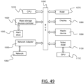
- FIG. 49 shows an example of the system, wherein the system is a client computer system, e.g. a workstation of a user.
- the system is a client computer system, e.g. a workstation of a user.
- the client computer of the example comprises a central processing unit (CPU) 1010 connected to an internal communication BUS 1000, a random access memory (RAM) 1070 also connected to the BUS.
- the client computer is further provided with a graphical processing unit (GPU) 1110 which is associated with a video random access memory 1100 connected to the BUS.
- Video RAM 1100 is also known in the art as frame buffer.
- a mass storage device controller 1020 manages accesses to a mass memory device, such as hard drive 1030.
- Mass memory devices suitable for tangibly embodying computer program instructions and data include all forms of nonvolatile memory, including by way of example semiconductor memory devices, such as EPROM, EEPROM, and flash memory devices; magnetic disks such as internal hard disks and removable disks; magneto-optical disks.
- a network adapter 1050 manages accesses to a network 1060.
- the client computer may also include a haptic device 1090 such as cursor control device, a keyboard or the like.
- a cursor control device is used in the client computer to permit the user to selectively position a cursor at any desired location on display 1080.
- the cursor control device allows the user to select various commands, and input control signals.
- the cursor control device includes a number of signal generation devices for input control signals to system.
- a cursor control device may be a mouse, the button of the mouse being used to generate the signals.
- the client computer system may comprise a sensitive pad, and/or a sensitive screen.
- the computer program may comprise instructions executable by a computer, the instructions comprising means for causing the above system to perform the method.
- the program may be recordable on any data storage medium, including the memory of the system.
- the program may for example be implemented in digital electronic circuitry, or in computer hardware, firmware, software, or in combinations of them.
- the program may be implemented as an apparatus, for example a product tangibly embodied in a machine-readable storage device for execution by a programmable processor. Method steps may be performed by a programmable processor executing a program of instructions to perform functions of the method by operating on input data and generating output.
- the processor may thus be programmable and coupled to receive data and instructions from, and to transmit data and instructions to, a data storage system, at least one input device, and at least one output device.
- the application program may be implemented in a high-level procedural or object-oriented programming language, or in assembly or machine language if desired. In any case, the language may be a compiled or interpreted language.
- the program may be a full installation program or an update program. Application of the program on the system results in any case in instructions for performing the method.
- the computer program may alternatively be stored and executed on a server of a cloud computing environment, the server being in communication across a network with one or more clients. In such a case a processing unit executes the instructions comprised by the program, thereby causing the method to be performed on the cloud computing environment.
Landscapes
- Physics & Mathematics (AREA)
- Engineering & Computer Science (AREA)
- Geometry (AREA)
- General Physics & Mathematics (AREA)
- Theoretical Computer Science (AREA)
- Pure & Applied Mathematics (AREA)
- General Engineering & Computer Science (AREA)
- Evolutionary Computation (AREA)
- Mathematical Analysis (AREA)
- Mathematical Optimization (AREA)
- Computer Hardware Design (AREA)
- Computational Mathematics (AREA)
- Software Systems (AREA)
- Computer Graphics (AREA)
- Automation & Control Theory (AREA)
- Aviation & Aerospace Engineering (AREA)
- Mathematical Physics (AREA)
- Algebra (AREA)
- Architecture (AREA)
- Human Computer Interaction (AREA)
- Image Generation (AREA)
Priority Applications (4)
| Application Number | Priority Date | Filing Date | Title |
|---|---|---|---|
| EP23306674.5A EP4535211A1 (fr) | 2023-10-02 | 2023-10-02 | Conversion d'une courbe de subdivision commandée par un maillage de base en un format de courbe de cao correspondant |
| US18/904,863 US20250111101A1 (en) | 2023-10-02 | 2024-10-02 | Converting a subdivision curve controlled by a base mesh into a corresponding cad curve format |
| JP2024173055A JP2025062587A (ja) | 2023-10-02 | 2024-10-02 | 対応するcad曲線形式への基本メッシュによって制御される細分割曲線の変換 |
| CN202411391273.3A CN119762711A (zh) | 2023-10-02 | 2024-10-08 | 将由基础网格控制的细分曲线转换为对应的cad曲线格式 |
Applications Claiming Priority (1)
| Application Number | Priority Date | Filing Date | Title |
|---|---|---|---|
| EP23306674.5A EP4535211A1 (fr) | 2023-10-02 | 2023-10-02 | Conversion d'une courbe de subdivision commandée par un maillage de base en un format de courbe de cao correspondant |
Publications (1)
| Publication Number | Publication Date |
|---|---|
| EP4535211A1 true EP4535211A1 (fr) | 2025-04-09 |
Family
ID=88315908
Family Applications (1)
| Application Number | Title | Priority Date | Filing Date |
|---|---|---|---|
| EP23306674.5A Pending EP4535211A1 (fr) | 2023-10-02 | 2023-10-02 | Conversion d'une courbe de subdivision commandée par un maillage de base en un format de courbe de cao correspondant |
Country Status (4)
| Country | Link |
|---|---|
| US (1) | US20250111101A1 (fr) |
| EP (1) | EP4535211A1 (fr) |
| JP (1) | JP2025062587A (fr) |
| CN (1) | CN119762711A (fr) |
Families Citing this family (3)
| Publication number | Priority date | Publication date | Assignee | Title |
|---|---|---|---|---|
| US20260080187A1 (en) * | 2024-09-18 | 2026-03-19 | Arcade Studio, Inc. | Using artificial intelligence to generate images of product based on user input |
| CN120449320B (zh) * | 2025-07-03 | 2025-09-09 | 深圳市瑞达飞行科技有限公司 | 融合qar和ai的飞行品质评价方法、装置及存储介质 |
| CN120510328B (zh) * | 2025-07-22 | 2025-10-14 | 山东捷瑞信息技术产业研究院有限公司 | 一种三维几何体自适应拓扑轮廓渐变结构生成方法 |
Citations (4)
| Publication number | Priority date | Publication date | Assignee | Title |
|---|---|---|---|---|
| US6950099B2 (en) * | 2002-07-01 | 2005-09-27 | Alias Systems Corp. | Approximation of Catmull-Clark subdivision surfaces by Bezier patches |
| CA2554361A1 (fr) * | 2005-08-04 | 2007-02-04 | Dassault Systemes | Methode de formation d'un ensemble isotopologique de surfaces parametrees a partir d'une maille |
| EP1750228A2 (fr) | 2005-08-04 | 2007-02-07 | Dassault Systèmes | Procédé de génération d'une surface paramétrique avec une continuité géometrique déterminée |
| EP3327593A1 (fr) | 2016-11-25 | 2018-05-30 | Dassault Systèmes | Orientation d'un objet réel pour impression 3d |
-
2023
- 2023-10-02 EP EP23306674.5A patent/EP4535211A1/fr active Pending
-
2024
- 2024-10-02 US US18/904,863 patent/US20250111101A1/en active Pending
- 2024-10-02 JP JP2024173055A patent/JP2025062587A/ja active Pending
- 2024-10-08 CN CN202411391273.3A patent/CN119762711A/zh active Pending
Patent Citations (4)
| Publication number | Priority date | Publication date | Assignee | Title |
|---|---|---|---|---|
| US6950099B2 (en) * | 2002-07-01 | 2005-09-27 | Alias Systems Corp. | Approximation of Catmull-Clark subdivision surfaces by Bezier patches |
| CA2554361A1 (fr) * | 2005-08-04 | 2007-02-04 | Dassault Systemes | Methode de formation d'un ensemble isotopologique de surfaces parametrees a partir d'une maille |
| EP1750228A2 (fr) | 2005-08-04 | 2007-02-07 | Dassault Systèmes | Procédé de génération d'une surface paramétrique avec une continuité géometrique déterminée |
| EP3327593A1 (fr) | 2016-11-25 | 2018-05-30 | Dassault Systèmes | Orientation d'un objet réel pour impression 3d |
Non-Patent Citations (1)
| Title |
|---|
| GAVRIIL KONSTANTINOS GUSEYNOV RUSLAN@GMAIL COM ET AL: "Computational design of cold bent glass façades", ACM TRANSACTIONS ON GRAPHICS, ACM, NY, US, vol. 39, no. 6, 26 November 2020 (2020-11-26), pages 1 - 16, XP058683281, ISSN: 0730-0301, DOI: 10.1145/3414685.3417843 * |
Also Published As
| Publication number | Publication date |
|---|---|
| US20250111101A1 (en) | 2025-04-03 |
| CN119762711A (zh) | 2025-04-04 |
| JP2025062587A (ja) | 2025-04-14 |
Similar Documents
| Publication | Publication Date | Title |
|---|---|---|
| EP4535211A1 (fr) | Conversion d'une courbe de subdivision commandée par un maillage de base en un format de courbe de cao correspondant | |
| EP4254252A1 (fr) | Optimisation de modèle de cao à base de gradient | |
| EP3674932B1 (fr) | Modélisation à l'aide d'une définition de type faible | |
| US20240403502A1 (en) | Designing a manufacturing product having one or more mechanical functionalities | |
| US20230418986A1 (en) | Cad feature tree optimization | |
| US20250111102A1 (en) | Subdivision curve deformation | |
| US20250315562A1 (en) | Generating a cad feature tree from a discrete geometrical representation of a mechanical part | |
| US20230418990A1 (en) | Cad feature tree generation | |
| US20230306162A1 (en) | Sketch-processing | |
| JP2024050514A (ja) | フィレット検出方法 | |
| EP4675484A1 (fr) | Résolveur de jonction de surface médiane globale | |
| EP4641424A1 (fr) | Détection de profil dans un modèle 3d discret représentant une partie mécanique | |
| EP4492274A1 (fr) | Procédé de détection de élément conique | |
| US12367643B2 (en) | Processing a tesselation | |
| EP4641429A1 (fr) | Détection de caractéristiques de coque ou de décalage dans un modèle 3d représentant une pièce mécanique |
Legal Events
| Date | Code | Title | Description |
|---|---|---|---|
| PUAI | Public reference made under article 153(3) epc to a published international application that has entered the european phase |
Free format text: ORIGINAL CODE: 0009012 |
|
| STAA | Information on the status of an ep patent application or granted ep patent |
Free format text: STATUS: THE APPLICATION HAS BEEN PUBLISHED |
|
| AK | Designated contracting states |
Kind code of ref document: A1 Designated state(s): AL AT BE BG CH CY CZ DE DK EE ES FI FR GB GR HR HU IE IS IT LI LT LU LV MC ME MK MT NL NO PL PT RO RS SE SI SK SM TR |
|
| STAA | Information on the status of an ep patent application or granted ep patent |
Free format text: STATUS: REQUEST FOR EXAMINATION WAS MADE |
|
| 17P | Request for examination filed |
Effective date: 20251009 |