EP4535331A1 - Dispositif de coordination, unité de bord de route, système de commande de mouvement, programme, procédé de commande de mouvement et corps mobile - Google Patents
Dispositif de coordination, unité de bord de route, système de commande de mouvement, programme, procédé de commande de mouvement et corps mobile Download PDFInfo
- Publication number
- EP4535331A1 EP4535331A1 EP23819526.7A EP23819526A EP4535331A1 EP 4535331 A1 EP4535331 A1 EP 4535331A1 EP 23819526 A EP23819526 A EP 23819526A EP 4535331 A1 EP4535331 A1 EP 4535331A1
- Authority
- EP
- European Patent Office
- Prior art keywords
- moving body
- unit
- prohibited section
- movement
- prohibited
- Prior art date
- Legal status (The legal status is an assumption and is not a legal conclusion. Google has not performed a legal analysis and makes no representation as to the accuracy of the status listed.)
- Pending
Links
Images





Classifications
-
- G—PHYSICS
- G08—SIGNALLING
- G08G—TRAFFIC CONTROL SYSTEMS
- G08G1/00—Traffic control systems for road vehicles
- G08G1/09—Arrangements for giving variable traffic instructions
- G08G1/0962—Arrangements for giving variable traffic instructions having an indicator mounted inside the vehicle, e.g. giving voice messages
- G08G1/0967—Systems involving transmission of highway information, e.g. weather, speed limits
- G08G1/096708—Systems involving transmission of highway information, e.g. weather, speed limits where the received information might be used to generate an automatic action on the vehicle control
- G08G1/096725—Systems involving transmission of highway information, e.g. weather, speed limits where the received information might be used to generate an automatic action on the vehicle control where the received information generates an automatic action on the vehicle control
-
- G—PHYSICS
- G08—SIGNALLING
- G08G—TRAFFIC CONTROL SYSTEMS
- G08G1/00—Traffic control systems for road vehicles
- G08G1/01—Detecting movement of traffic to be counted or controlled
- G08G1/0104—Measuring and analyzing of parameters relative to traffic conditions
- G08G1/0108—Measuring and analyzing of parameters relative to traffic conditions based on the source of data
- G08G1/0112—Measuring and analyzing of parameters relative to traffic conditions based on the source of data from the vehicle, e.g. floating car data [FCD]
-
- G—PHYSICS
- G08—SIGNALLING
- G08G—TRAFFIC CONTROL SYSTEMS
- G08G1/00—Traffic control systems for road vehicles
- G08G1/01—Detecting movement of traffic to be counted or controlled
- G08G1/0104—Measuring and analyzing of parameters relative to traffic conditions
- G08G1/0108—Measuring and analyzing of parameters relative to traffic conditions based on the source of data
- G08G1/0116—Measuring and analyzing of parameters relative to traffic conditions based on the source of data from roadside infrastructure, e.g. beacons
-
- G—PHYSICS
- G08—SIGNALLING
- G08G—TRAFFIC CONTROL SYSTEMS
- G08G1/00—Traffic control systems for road vehicles
- G08G1/01—Detecting movement of traffic to be counted or controlled
- G08G1/0104—Measuring and analyzing of parameters relative to traffic conditions
- G08G1/0125—Traffic data processing
- G08G1/0133—Traffic data processing for classifying traffic situation
-
- G—PHYSICS
- G08—SIGNALLING
- G08G—TRAFFIC CONTROL SYSTEMS
- G08G1/00—Traffic control systems for road vehicles
- G08G1/09—Arrangements for giving variable traffic instructions
- G08G1/0962—Arrangements for giving variable traffic instructions having an indicator mounted inside the vehicle, e.g. giving voice messages
- G08G1/0967—Systems involving transmission of highway information, e.g. weather, speed limits
- G08G1/096766—Systems involving transmission of highway information, e.g. weather, speed limits where the system is characterised by the origin of the information transmission
- G08G1/096775—Systems involving transmission of highway information, e.g. weather, speed limits where the system is characterised by the origin of the information transmission where the origin of the information is a central station
-
- G—PHYSICS
- G08—SIGNALLING
- G08G—TRAFFIC CONTROL SYSTEMS
- G08G1/00—Traffic control systems for road vehicles
- G08G1/20—Monitoring the location of vehicles belonging to a group, e.g. fleet of vehicles, countable or determined number of vehicles
- G08G1/207—Monitoring the location of vehicles belonging to a group, e.g. fleet of vehicles, countable or determined number of vehicles with respect to certain areas, e.g. forbidden or allowed areas with possible alerting when inside or outside boundaries
Definitions
- the present invention relates to a traffic control device, a roadside unit, a movement control system, a program, a movement control method, and a moving body.
- Patent document 1 is an example of this type of technology.
- Patent document 1 describes a device including: an acquisition means for acquiring automatic travel information which is information relating to a host vehicle and a state around the host vehicle; an automatic travel means for performing automatic travel by controlling a traveling direction and a speed of the host vehicle based on the automatic travel information; a determination means for determining whether or not a problem related to the automatic travel information has occurred; and a change means for changing, in the case of a problem occurring, a traveling state of the host vehicle or a traveling state of another vehicle in accordance with the content of the problem.
- Patent Document 1 Japanese Unexamined Patent Application, Publication No. 2016-181031
- an object of the present invention is to provide a traffic control device, a roadside unit, a movement control system, a program, and a movement control method that can support safe movement of a moving body with a simpler configuration and processing. Further, it is another object of the present invention to provide a moving body that is managed and controlled by the traffic control device.
- the moving body information acquisition unit 110 executes processing of acquiring information relating to the moving body 3 traveling in the communicable area of the roadside unit 1.
- the moving body information acquisition unit 110 includes the identification information acquisition unit 111, the positional information acquisition unit 112, and the travel information acquisition unit 113.
- the prohibited section A of the roadside unit 1 is formed in regions on both sides of the road 4 (regions on the road side and the periphery thereof).
- the prohibited section A on the lower side of the drawing shows the positional relationship of the prohibited section A on the road 4, and the prohibited section A and the moving body 3 on the upper side of the drawing virtually show the contents of the comparison processing of the positional information of the moving body 3 and the prohibited section A by the processing unit 10 described later.
- the prohibited section information includes information indicating an alarm area B set around the prohibited section A. That is, the alarm area B is an area in which there is a high possibility that the moving body 3 will move out of the prohibited section A when the moving body 3 continues to move. In the present embodiment, the alarm area B is provided so as to surround the prohibited section A in a plan view.
- the prohibited section information acquisition unit 120 executes processing of acquiring prohibited section information from the traffic control server 2 or the storage unit 11. In the present embodiment, when the prohibited section information is received from the traffic control server 2, the prohibited section information acquisition unit 120 updates the prohibited section information stored in the storage unit 11 to the received prohibited section information.
- the signal output processing unit 130 executes processing of outputting various signals for controlling the moving body 3 based on the positional information of the moving body 3 and the like.
- the signal output processing unit 130 includes a mode switching signal output processing unit 131, a prohibition signal output processing unit 132, and an alarm signal output processing unit 133.
- the mode switching signal output processing unit 131 executes processing of outputting the first mode switching signal based on the positional information of the moving body 3 and the prohibited section information.
- the first mode switching signal is a control signal including an instruction to perform mode switching for switching the mode in which the moving body 3 moves to the controlled mode or the non-controlled mode.
- the controlled mode refers to a mode in which the operation of the moving body 3 is controlled in accordance with a control signal such as a prohibition signal P or an alarm signal transmitted from the roadside unit 1.
- the non-controlled mode is a mode in which the operation of the moving body 3 is not controlled by a control signal such as the prohibition signal P or the alarm signal transmitted from the roadside unit 1.
- FIGS. 4A and 4B are diagrams for explaining the relationship between the control target area C and the prohibited section A.
- the prohibited section A is indicated by a one-dot chain line
- the control target area C is indicated by a broken line.
- the control target area C is set to be outside the entrance and the exit of the prohibited section A in the traveling direction of the moving body 3 on the road 4 and to be wider than the widths of the two prohibited sections A.
- the control target area C may be set to be at the same place as the entrance and the exit of the alarm area B existing around the prohibited section A and to be wider than the widths of the two prohibited sections A.
- the mode switching signal output processing unit 131 when it is determined that the moving body 3 has entered the control target area C based on the positional information of the moving body 3, the mode switching signal output processing unit 131 outputs a first mode switching signal for performing mode switching from the non-controlled mode to the controlled mode. In addition, when it is determined that the moving body 3 has exited the control target area C based on the positional information of the moving body 3, the mode switching signal output processing unit 131 outputs the first mode switching signal for executing mode switching from the controlled mode to the non-controlled mode.
- the prohibition signal output processing unit 132 executes processing of outputting the prohibition signal P for prohibiting the movement of the moving body 3 in the controlled mode.
- the prohibition signal output processing unit 132 compares the positional information of the moving body 3 with the prohibited section information, and outputs the prohibition signal P based on the comparison result. Specifically, the prohibition signal output processing unit 132 determines whether or not the moving body 3 exists in the prohibited section A based on the comparison result between the positional information of the moving body 3 and the prohibited section information, and outputs the prohibition signal P when it is determined that the moving body 3 exists in the prohibited section A.
- the prohibition signal output processing unit 132 may determine that the moving body 3 exists in the prohibited section A only when the entire moving body 3 is located in the prohibited section A by using the information relating to the size of the moving body 3, which is the identification information. For example, the prohibition signal output processing unit 132 may determine that the moving body exists in the prohibited section A when at least a part of the moving body 3 is located in the prohibited section A. Further, when the center of the vehicle body of the moving body 3 is located in the prohibited section A, it may be determined that the moving body 3 exists in the prohibited section A. For example, the moving body 3 receives control for restricting the continuous travel when the prohibition signal P is received in the controlled mode, and is allowed to perform the continuous travel when the prohibition signal P is not received.
- the alarm signal output processing unit 133 executes processing of outputting an alarm signal based on the positional information of the moving body 3 and the prohibited section information.
- the alarm signal refers to a control signal including an instruction to cause the moving body 3 to perform processing of generating an alarm that alerts the operator of the moving body 3.
- the alarm signal output processing unit 133 compares the positional information with the information indicating the alarm area B included in the prohibited section information, and determines whether or not the moving body 3 exists in the alarm area B based on the comparison result. When it is determined that the moving body 3 exists in the alarm area B, the alarm signal output processing unit 133 outputs an alarm signal indicating that the moving body 3 exists in the alarm area B to the moving body 3.
- FIG. 5 is a block diagram illustrating a configuration of hardware and functional blocks of the traffic control server 2.
- the traffic control server 2 includes a processing unit 20, a storage unit 21, and a communication I/F 22.
- the processing unit 20 is an arithmetic device configured by a processor such as a CPU, and reads and executes various programs and data from the storage unit 21 described later to realize a function of movement control.
- the processing unit 20 executes data processing of each functional unit of a roadside unit information acquisition unit 210, a map information management unit 220, a prohibited section information management unit 230, and a mode switching signal output processing unit 240.
- the operation of each functional unit will be described later.
- the function of the movement control of the processing unit 20 may be realized by hardware or software.
- the storage unit 21 is a storage area for various programs for causing a hardware group to function as the traffic control server 2, various data, and the like, and can be configured by ROM, RAM, flash memory, a semiconductor drive (SSD), hardware (HDD), or the like.
- the storage unit 21 stores a program for causing the processing unit 20 to execute each function of the present embodiment, a control program of the traffic control server 2, various parameters, data used for movement control of the moving body 3, identification information such as IP addresses and MAC addresses of a plurality of roadside units 1 communicably connected to the traffic control server 2, geographical map information including communicable areas of the plurality of roadside units 1, and prohibited section information in each communicable area of the plurality of roadside units 1.
- the communication I/F 22 is an interface for the traffic control server 2 to communicate via the communication network NW.
- the traffic control server 2 is communicably connected to the plurality of roadside units 1 and other communication devices via the communication I/F 22.
- the roadside unit information acquisition unit 210 executes processing of acquiring roadside unit information transmitted from each of the plurality of roadside units 1.
- Examples of the roadside unit information include moving body information acquired by each of the plurality of roadside units 1, information relating to an event occurring on the road 4, and information relating to an output state of various control signals by the roadside unit 1.
- Examples of the information relating to the event include a traffic accident, traffic congestion, a breakdown of a vehicle, traveling of an emergency vehicle, a road surface abnormality, a fire, traveling of a maintenance vehicle on the road 4, and the like.
- the roadside unit information acquisition unit 210 acquires information such as identification information, positional information, and travel information of the moving body 3 traveling in the communicable area of each roadside unit 1, information relating to the occurrence situation of a traffic accident on the road 4, and the like.
- Examples of the information relating to the output status of the various control signals include the presence or absence of the output of the first mode switching signal, the alarm signal, the prohibition signal P, and the like.
- the map information management unit 220 generates map information based on information acquired from the outside and updates the map information as needed.
- the map information may be, for example, a dynamic map.
- the dynamic map is a combination of static information such as road surface information, lane information, and structures, and dynamic information such as traffic regulations, construction, congestion, vehicles, pedestrians, and signals, and is a three-dimensional digital map having latitude, longitude, and altitude information.
- the map information management unit 220 updates the dynamic map as needed based on information acquired from the outside, and transmits the dynamic map to each of the plurality of roadside units 1.
- the map information transmitted to each roadside unit 1 is transmitted from the roadside unit 1 to the moving body 3 while traveling.
- the prohibited section information management unit 230 executes processing of generating and managing prohibited section information for each of the plurality of roadside units 1. Specifically, the prohibited section information management unit 230 generates prohibited section information for each of the plurality of roadside units 1 based on information acquired via the communication network NW or a predetermined program stored in the storage unit 21. Then, the prohibited section information management unit 230 transmits the generated prohibited section information to the corresponding roadside unit 1.
- the prohibited section information management unit 230 may generate different prohibited section information depending on, for example, a time period.
- the prohibited section information management unit 230 may provide the prohibited section A on the road side of the road 4, and may set the size of the prohibited section A in a time period such as the morning or evening when children go (back) to school (hereinafter, referred to as a school time period) to be larger than other time periods. Further, for example, the prohibited section information management unit 230 may provide the prohibited section A only in the school time period. The prohibited section information management unit 230 may generate different prohibited section information based on information acquired from the outside. For example, the prohibited section information management unit 230 may change the prohibited section information based on the information relating to the event acquired from the roadside unit 1.
- the prohibited section information management unit 230 may generate the prohibited section information indicating the prohibited section A provided at and around the accident occurrence location. Further, for example, when acquiring information indicating that a maintenance vehicle is traveling on an expressway, the prohibited section information management unit 230 may generate the prohibited section information for the maintenance vehicle to move.
- the mode switching signal output processing unit 240 executes processing of outputting a second mode switching signal (operation mode switching signal).
- the second mode switching signal refers to a control signal including a command to execute driving mode switching for switching the driving mode of the moving body 3 to the autonomous driving mode or the remote driving mode.
- the mode switching signal output processing unit 240 may output the second mode switching signal based on the output state of the prohibition signal P by the signal output processing unit 130 of the roadside unit 1, for example. Specifically, in a case where it is determined that the prohibition signal P is outputted from the roadside unit 1, the mode switching signal output processing unit 240 may output the second mode switching signal to execute driving mode switching for switching the driving mode of the moving body 3 from the autonomous driving mode to the remote driving mode.
- the mode switching signal output processing unit 240 may output the second mode switching signal to execute driving mode switching for switching the driving mode of the moving body 3 from the remote driving mode to the autonomous driving mode, for example.
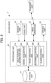
- FIG. 6 is a block diagram illustrating the configuration of hardware and functional blocks of the moving body 3.
- the moving body 3 includes the processing unit 30, the storage unit 31, the wireless communication unit 32, the sensor unit 33, the GNSS unit 34, and the driving unit 35.
- the processing unit 30 is an arithmetic device configured by a processor such as a CPU, and reads and executes various programs and data from the storage unit 31 described later to realize a function of movement control.
- the processing unit 30 executes data processing of each functional unit of a self-position estimation unit 310, a signal acquisition unit 320, a mode switching unit 330, a movement control unit 340, and an alarm control unit 350. The operation of each functional unit will be described later.
- the storage unit 31 is a storage area for various programs and various data for causing a hardware group to function as the moving body 3, and can be configured by ROM, RAM, flash memory, a semiconductor drive (SSD), hardware (HDD), or the like. Specifically, the storage unit 31 stores a program (a control program of the moving body 3) for causing the processing unit 30 to execute each function of the present embodiment, various parameters, data used for movement control of the moving body 3, identification information such as an identification ID and an IP address of the moving body 3, map information, and the like. Examples of the map information include a dynamic map.
- the wireless communication unit 32 executes processing for the moving body 3 to wirelessly communicate with the roadside unit 1.
- the wireless communication unit 32 transmits, for example, identification information for identifying the moving body 3, positional information indicating the position of the moving body 3, travel information of the moving body 3, and the like to the roadside unit 1, and receives various control signals such as the first mode switching signal, the prohibition signal P, and the alarm signal, the map information generated by the traffic control server 2, and the like from the roadside unit 1.
- the wireless communication unit 32 communicates with the processing unit 10 via the wireless communication unit 13 of the roadside unit 1.
- the sensor unit 33 is a device for detecting information relating to the surroundings of the moving body 3 itself.
- the sensor unit 33 may be, for example, radar or LIDAR (light detection and ranging) that detects a distance, a direction, a relative speed, or the like relative to an object present around the moving body 3 based on a transmission wave transmitted to the periphery of the moving body 3 and a reflected received wave, or may be a camera or the like.
- LIDAR is used which irradiates laser light around the moving body 3 and detects a surrounding object as point cloud data. According to LIDAR, it is possible to detect the position, the shape, and the like of the surrounding object with high accuracy.
- the sensor unit 33 transmits the detected point cloud data to the processing unit 30.
- the GNSS (Global Navigation Satellite System) unit 34 includes an antenna and receives a GNSS signal and the like.
- the GNSS signal is transmitted from a navigation satellite or the like that make up a GNSS such as GPS (Global Positioning System) or a quasi-zenith satellite system.
- the GNSS unit 34 transmits the received GNSS signal to the processing unit 30.
- the driving unit 35 is a part related to driving of the moving body 3, such as an engine, a motor, or a brake.
- the self-position estimation unit 310 executes processing of estimating positional information indicating the position of the moving body 3 itself.
- the self-position estimation unit 310 may estimate the positional information of the moving body 3 based on the map information received from the traffic control server 2, the point cloud data around the moving body 3 received from the sensor unit 33, the GNSS signal received from the GNSS unit 34, and the like. More specifically, the self-position estimation unit 310 may estimate the positional information of the moving body 3 by collating the map information with the point cloud data around the moving body 3.
- the positional information estimated by the self-position estimation unit 310 is transmitted to the roadside unit 1 via the wireless communication unit 32.
- the signal acquisition unit 320 executes processing of acquiring various control signals such as the first mode switching signal, the second mode switching signal, the prohibition signal P, and the alarm signal from the roadside unit 1 via the wireless communication unit 32.
- the mode switching unit 330 switches the movement mode of the moving body 3. Specifically, when the first mode switching signal for executing mode switching from the non-controlled mode to the controlled mode is acquired in a state where the movement mode of the moving body 3 is the non-controlled mode, the mode switching unit 330 switches the movement mode to the controlled mode. On the other hand, when the first mode switching signal for performing mode switching from the controlled mode to the non-controlled mode is acquired in a state where the movement mode of the moving body 3 is the controlled mode, the mode switching unit 330 switches the movement mode from the controlled mode to the non-controlled mode.
- the mode switching unit 330 switches the operation mode of the moving body 3. Specifically, when the second mode switching signal is acquired in a state where the driving mode of the moving body 3 is the autonomous driving mode, the mode switching unit 330 switches the driving mode to the remote driving mode. Conversely, when the second mode switching signal is acquired in a state where the driving mode of the moving body 3 is the remote driving mode, the mode switching unit 330 switches the driving mode from the remote driving mode to the autonomous driving mode.
- the movement control unit 340 executes processing of controlling the movement of the moving body 3 based on the positional information, etc. estimated by the self-position estimation unit 310. Specifically, the movement control unit 340 controls the movement to the set destination by controlling the driving of the driving unit 35 based on the positional information and the travel information of the moving body 3, the map information stored in the storage unit 31, and the like.
- the movement control unit 340 stops the autonomous driving and executes processing of controlling the movement of the moving body 3 based on the remote operation signal.
- the remote control signal may be transmitted to the moving body 3 via the communication network NW from a facility such as a traffic control center having, for example, the traffic control server 2.
- the remote control signal may be generated as a signal such that the moving body 3 moves to the outside of the prohibited section A based on, for example, the positional information of the moving body 3 or the map information acquired via the traffic control server 2, the prohibited section information, the image captured by the moving body 3 or the roadside unit 1, or the like.
- the movement control unit 340 executes processing of controlling the driving of the moving body 3 based on the acquisition status of the prohibition signal P by the signal acquisition unit 320.
- the prohibition signal P transmitted from the processing unit 10 of the roadside unit 1 is received by the wireless communication unit 32, the movement control unit 340 controls the driving unit 35 to perform an operation corresponding to the prohibition signal P.
- the operation corresponding to the prohibition signal P refers to, for example, an operation of stopping the driving of the moving body 3 or an operation for the moving body 3 to leave from the prohibited section A.
- the movement control unit 340 may execute control for stopping the moving body 3, and may control the moving body 3 so that the moving body 3 in the prohibited section A leaves the prohibited section A.
- the control for stopping the moving body 3 may be, for example, control for stopping the moving body 3 after decelerating to a predetermined speed.
- the movement control unit 340 may execute control for stopping the moving body 3 or control for leaving the prohibited section A.
- the alarm control unit 350 executes processing for generating an alarm.
- the alarm may be audio information, textual information, or the like to inform the operator of the moving body 3 of the possibility of entering the prohibited section A.
- the alarm control unit 350 may display an alarm on a liquid crystal display or a mirror disposed in the moving body 3 or may generate audio information from a speaker disposed in the moving body 3.
- the moving body 3 is traveling between two prohibited sections A on the road 4.
- the prohibition signal output processing unit 132 of the roadside unit 1 the moving body 3 is located outside the prohibited section A, and thus the prohibition signal P is not outputted. Therefore, the moving body 3 is continuously running.
- FIG. 7 is a flowchart showing an example of processing up to the output of the first mode switching signal in the movement control executed by the processing unit 10 of the roadside unit 1
- FIG. 8 is a flowchart showing an example of processing for controlling the moving body 3 in the controlled mode.
- the processing unit 10 executes the processing of FIGS. 7 and 8 based on, for example, a program stored in the storage unit 11 or the like.
- the flows of the processing exemplified in FIGS. 7 and 8 each start the processing when the installed roadside unit 1 is activated, and then continue the processing during the operation of the roadside unit 1.
- step S11 the positional information acquisition unit 112 acquires the positional information of the moving body 3 received via the wireless communication unit 13.
- step S12 the mode switching signal output processing unit 131 compares the positional information acquired in step S11 with the information indicating the position of the control target area C stored in the storage unit 11, and determines whether the moving body 3 has entered the control target area C. When it is determined that the moving body 3 has entered the control target area C (step S12; YES), the mode switching signal output processing unit 131 proceeds to step S13. On the other hand, when it is determined that the moving body 3 is located outside the control target area C (step S12; NO), the mode switching signal output processing unit 131 repeats the processing of step S11.
- step S13 the mode switching signal output processing unit 131 outputs the first mode switching signal for switching the moving body 3 to the controlled mode. Then, the first mode switching signal is transmitted to the moving body 3 by the wireless communication unit 13.
- step S21 the prohibited section information acquisition unit 120 extracts the prohibited section information from the storage unit 11.
- step S22 the positional information acquisition unit 112 acquires the positional information of the moving body 3 received via the wireless communication unit 13.
- step S23 the prohibition signal output processing unit 132 compares the prohibited section information acquired in step S21 with the positional information acquired in step S22, and determines whether or not the moving body 3 is located within the prohibited section A.
- step S23; YES the processing proceeds to step S24.
- step S23; NO the processing of step S22 is repeated.
- step S24 the prohibition signal output processing unit 132 outputs the prohibition signal P for prohibiting the movement of the moving body 3 in the prohibited section A. Then, the prohibition signal P is transmitted to the moving body 3 by the wireless communication unit 13. Thereafter, the processing unit 10 returns the processing to step S22.
- FIG. 9 is a flowchart illustrating an example of processing of the movement control executed by the processing unit 20 of the traffic control server 2.
- the processing unit 20 executes the processing of FIG. 9 based on, for example, a program stored in the storage unit 21 or the like.
- the flow of processing illustrated in FIG. 9 starts the processing when the traffic control server 2 installed is activated, and then continues the processing while the traffic control server 2 is operating.
- the roadside unit information acquisition unit 210 acquires roadside unit information that is transmitted from each of the plurality of roadside units 1, and includes the output status of the prohibition signal P by each of the roadside units 1 and the positional information of the moving body 3.
- step S32 the mode switching signal output processing unit 240 determines whether or not the prohibition signal P is outputted by the roadside unit 1 based on the roadside unit information acquired in step S31.
- the mode switching signal output processing unit 240 causes the processing to proceed to step S33.
- the mode switching signal output processing unit 240 returns the processing to step S31.
- step S33 the mode switching signal output processing unit 240 outputs the second mode switching signal. Then, the second mode switching signal is transmitted to the moving body 3 via the roadside unit 1 and the wireless communication unit 13 which outputted the prohibition signal P.
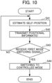
- FIG. 10 is a flowchart showing an example of processing executed by the moving body 3 until the movement mode is switched to the controlled mode
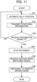
- FIG. 11 is a flowchart showing an example of processing executed by the moving body 3 in the controlled mode. It is to be noted that the moving body 3 at the start of the flow of FIG. 10 assumes that the movement mode is the non-controlled mode and the driving mode is the autonomous driving mode.
- the self-position estimation unit 310 estimates the positional information indicating the position of the moving body 3 itself.
- the self-position estimation unit 310 estimates the positional information of the moving body 3 itself based on, for example, the map information received from the traffic control server 2 via the roadside unit 1 and point cloud data received from the sensor unit 33.
- step S42 the wireless communication unit 32 transmits the positional information of the moving body 3 estimated in step S41 to the roadside unit 1.
- step S43 the mode switching unit 330 determines whether or not the first mode switching signal has been received from the roadside unit 1. When it is determined that the first mode switching signal has been acquired by the signal acquisition unit 320 (step S43; YES), the mode switching unit 330 causes the processing to proceed to step S44. On the other hand, when it is determined that the signal acquisition unit 320 has not acquired the first mode switching signal (step S43; NO), the mode switching unit 330 returns the processing to step S31.
- step S44 the mode switching unit 330 switches the movement mode of the moving body 3 to the controlled mode.
- the self-position estimation unit 310 estimates the positional information indicating the position of the moving body 3 itself.
- the self-position estimation unit 310 estimates the positional information of the moving body 3 itself based on, for example, the map information received from the traffic control server 2 via the roadside unit 1 and point cloud data received from the sensor unit 33.
- step S52 the wireless communication unit 32 transmits the positional information of the moving body 3 estimated in step S51 to the roadside unit 1.
- step S53 the movement control unit 340 determines whether or not the signal acquisition unit 320 has received the prohibition signal P.
- the movement control unit 340 causes the processing to proceed to step S54.
- the movement control unit 340 returns the processing to step S51.
- step S54 the movement control unit 340 controls the driving unit 35 to stop the movement of the moving body 3.
- step S55 the processing unit 30 receives the second mode switching signal from the traffic control server 2. Then, the mode switching unit 330 switches the driving mode of the moving body 3 from the autonomous driving mode to the remote driving mode.
- the processing unit 10 includes the positional information acquisition unit 112 that acquires positional information indicating the position of the moving body 3, and the signal output processing unit 130 that compares the positional information with the prohibited section information indicating the prohibited section A in which the movement of the moving body 3 is prohibited, and outputs the prohibition signal P that prohibits the movement of the moving body 3 in the prohibited section A based on the result of the comparison.
- the signal output processing unit 130 determines whether the moving body 3 exists in the prohibited section A based on the result of the comparison, and when it is determined that the moving body 3 exists in the prohibited section A, outputs the prohibition signal P.
- the prohibited section information includes information indicating the alarm area B set around the prohibited section A
- the signal output processing unit 130 determines whether the moving body 3 exists in the alarm area B based on a result of the comparison, and when it is determined that the moving body 3 exists in the alarm area B, outputs an alarm signal for causing the moving body 3 to execute the processing whereby the moving body 3 generates an alarm.
- the moving body 3 is the moving body 3 which is configured to move autonomously. With such a configuration, even if an abnormality occurs in the traveling of the self-driving vehicle, it is possible to suppress the traveling of the self-driving vehicle in the prohibited section A.
- the roadside unit 1 is the roadside unit 1 which includes each constituent element of the processing unit 10, and is installed on the road 4 on which the moving body 3 moves or at the roadside of the road 4. With such a configuration, it is possible to assist in the safe movement of the moving body 3 traveling on the road 4 by a simple configuration and processing.
- the movement control system S is configured to be able to perform wireless communication with the moving body 3, and includes the plurality of roadside units 1 each installed in a different area, and the traffic control server 2 communicably connected to the plurality of roadside units 1.
- the traffic control server 2 includes the prohibited section information management unit 230 that generates the prohibited section information indicating the prohibited section A in which the movement of the moving body 3 is prohibited and transmits the prohibited section information to each of the plurality of roadside units 1.
- the roadside unit 1 includes the positional information acquisition unit 112 that acquires positional information indicating the position of the moving body 3 and the signal output processing unit 130 that compares the positional information with the prohibited section information received from the traffic control server 2 and outputs the prohibition signal P that prohibits the movement of the moving body 3 in the prohibited section A based on a result of the comparison.
- the signal output processing unit 130 determines whether the moving body 3 exists in the prohibited section A based on the result of the comparison, and when it is determined that the moving body 3 exists in the prohibited section A, outputs the prohibition signal P. With such a configuration, it is possible to prevent the moving body 3 from moving in an area where there is a risk of danger, by simple processing of comparing the position of the moving body 3 with the prohibited section A.
- the prohibited section A in an area including the oncoming lane, the road side, and the sidewalk of the road 7, it is possible to prevent the moving body 3 from entering the area and causing an accident if an abnormality occurs in the control of the self-driving vehicle or if an elderly driver erroneously performs a driving operation. Therefore, it is possible to assist in the safe movement of the moving body 3 with a simple configuration and processing.
- the prohibited section information includes information indicating the alarm area B set around the prohibited section A
- the signal output processing unit 130 of the roadside unit 1 determines whether the moving body 3 exists in the alarm area B based on the result of the comparison, and when it is determined that the moving body 3 exists in the alarm area B, outputs an alarm signal for causing the moving body 3 to perform processing of generating an alarm.
- the prohibited section information management unit 230 of the traffic control server 2 generates the prohibited section information which varies depending on a time period.
- the moving body 3 is a moving body 3 that is configured to move autonomously. With such a configuration, even if an abnormality occurs in the traveling of the self-driving vehicle, it is possible to suppress the traveling of the self-driving vehicle in the prohibited section A.
- the moving body 3 has driving modes including the autonomous driving mode in which the vehicle autonomously travels along a set travel route and the remote driving mode in which the vehicle travels based on a remote operation signal for remotely operating the moving body 3.
- the traffic control server 2 further includes the mode switching signal output processing unit 240 that outputs a driving mode switching signal for switching the driving mode of the moving body 3 to the remote driving mode when the prohibition signal P is outputted by the signal output processing unit 130.
- the program according to the present embodiment causes a computer included in the roadside unit 1 to execute: a positional information acquisition function of acquiring positional information indicating a position of the moving body 3; and a signal output processing function of comparing the positional information with prohibited section information indicating the prohibited section A in which the movement of moving body 3 is prohibited, and outputting the prohibition signal P for prohibiting the movement of moving body 3 in the prohibited section A based on a result of the comparison.
- the signal output processing function determines whether the moving body 3 exists in the prohibited section A based on the result of the comparison and, when it is determined that the moving body 3 exists in the prohibited section A, outputs the prohibition signal P.
- a movement control method is a movement control method executed by a roadside unit 1, and the method includes: a positional information acquisition step of acquiring positional information indicating a position of the moving body 3; and a signal output processing step of comparing the positional information with prohibited section information indicating the prohibited section A in which the movement of moving body 3 is prohibited, and outputting the prohibition signal P for prohibiting the movement of the moving body 3 based on a result of the comparison.
- the signal output processing step determines whether the moving body 3 exists in the prohibited section A based on the result of the comparison, and when it is determined that the moving body 3 exists in the prohibited section A, the signal output processing step outputs the prohibition signal P.
- the moving body 3 includes the wireless communication unit 32 that communicates with the processing unit 10, the self-position estimation unit 310 that estimates a self-position, the driving unit 35, and the movement control unit 340 that controls driving of the driving unit 35.
- the self-position estimation unit 310 transmits the estimated self-positional information to the processing unit 10 using the wireless communication unit 32.
- the movement control unit 340 controls the driving unit 35 to perform operation corresponding to the prohibition signal P when the movement control unit 340 receives the prohibition signal P transmitted from the processing unit 10 using the wireless communication unit 32.
- the moving body 3 in the above embodiment is a self-driving vehicle, it may be a vehicle that does not have an autonomous driving function. Further, the vehicle may be a four-wheeled motor vehicle or a two-wheeled motor vehicle. Also, the moving body 3 is not limited to vehicles and may be an unmanned flying object, such as a drone. In particular, in a case of an unmanned flying object, 3D map information made mainly using latitude, longitude, and altitude information is used.
- FIG. 12 is a schematic diagram illustrating an example of a flight path of an unmanned flying object to which the movement control system S according to a modification of the present embodiment is applied.
- the unmanned flying object is used for checking the state of electric wires 51 suspended by a steel tower 50, checking the state of a road or a wall surface in a tunnel, checking the state of a structure bridging over a river, a canal, a railway line, a road, or the like, checking a building, monitoring a river, a cliff, or a sea, and the like during a disaster.
- the state of the electric wires 51 of the steel tower 50 is inspected using an autonomously movable unmanned flying object.
- the prohibited section A in which the unmanned flying object can fly is defined by latitude, longitude, and altitude.
- the shape of the prohibited section A is a prismatic shape, but is not limited to this shape, and various shapes such as a cylindrical shape can be considered.
- the prohibited section A is set so as to surround the steel tower 50 and the electric wires 51.
- roadside units 1D, 1E, and 1F manage the prohibited section A.
- Each of the roadside units 1D, 1E, and 1F acquires the positional information from the unmanned flying object, compares the prohibited section information indicating the prohibited section A stored therein with the positional information of the unmanned flying object, and transmits the prohibition signal P to the unmanned flying object in a case in which the unmanned flying object is flying in the prohibited section A.
- a drone autonomous evacuation program for landing outside the prohibited section A on a safe route may be operated, or an emergency landing on the side opposite to the steel tower 50 may be performed. This makes it possible to prevent the unmanned flying object from coming into contact with the steel tower 50 and the electric wires 51 during inspection of the electric wires 51.
- the moving body 3 may also be a working robot.
- a prohibited section as an entry prohibited section may be set using 3D map information including information of latitude, longitude, and altitude.
- the moving body 3 can set a V2X communication terminal of a pedestrian or worker, also called V2P (Vehicle-to-Pedestrian) as its target.
- V2P Vehicle-to-Pedestrian
- each of the roadside units 1 includes the signal output processing unit 130, but the traffic control server 2 may acquire the positional information of the moving body 3 via each of the roadside units 1, and output the first mode switching signal, the prohibition signal P, and the alarm signal based on the comparison between the positional information and the prohibited section information.
- the traffic control server 2 outputs the second mode switching signal for switching the operation mode of the moving body 3, but each of the roadside units 1 may output the mode switching signal for switching the operation mode of the moving body 3 between the autonomous driving mode and the remote driving mode.
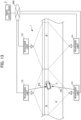
- FIG. 13 is a schematic diagram illustrating a movement control system S according to a modification of the present embodiment and an example of a road 4 to which the movement control system S is applied.
- the movement control system S includes a plurality of roadside units 1 including roadside units 1G and 1H which are installed on the road 4, or around or in the vicinity of the road 4 such as at the roadside of the road 4, and are capable of performing wireless communication with the moving body 3, which is a vehicle traveling on the road 4, and a traffic control server 2 communicably connected to each of the plurality of roadside units 1 via a communication network NW.
- the roadside units 1G and the roadside units 1H have the same configuration.
- the plurality of roadside units 1G are disposed at predetermined intervals along the road 4. Each of the roadside units 1H is disposed at a position opposite to a corresponding one of the roadside unit 1G across the road 4. Further, the plurality of roadside units 1G and the plurality of roadside units 1H may be disposed along the road 4 so as to cover the entire length of the prohibited section A, or one or a plurality of roadside units 1G and 1H may be disposed along the road 4 only at a specific place.
- the specific place refers to, for example, any place designated by the operator, such as a construction site.
- the prohibited section A of each of the plurality of roadside units 1 is set in such a manner that the entire prohibited sections A are overlapped with each other, but the present invention is not limited thereto, and the prohibited section A of each of the plurality of roadside units 1 is set in such a manner that the prohibited sections A are partially overlapped with each other.
- the moving body 3 when the moving body 3 is located in the overlapping prohibited sections A, the moving body 3 receives a plurality of prohibition signals P.
- the wireless communication unit 32 of the moving body 3 receives a plurality of prohibition signals P relating to movement into the same prohibited section A from different roadside units 1.
- the moving body 3 transmits the positional information to each of the roadside units 1G and the roadside units 1H.
- the roadside unit 1G transmits the positional information received from the moving body 3 to the traffic control server 2.
- the roadside unit 1H transmits the positional information received from the moving body 3 to the traffic control server 2.
- the traffic control server 2 generates a prohibition signal PG if the moving body 3 exists in the prohibited section A based on the positional information received from the roadside unit 1G, and transmits the generated prohibition signal PG to the roadside unit 1G. Then, the roadside unit 1G transmits the prohibition signal PG to the moving body 3. In addition, the traffic control server 2 generates a prohibition signal PH if the moving body 3 exists in the prohibited section A based on the positional information received from the roadside unit 1H, and transmits the generated prohibition signal PH to the roadside unit 1H. Then, the roadside unit 1H transmits the prohibition signal PH to the moving body 3.
- the wireless communication unit 32 of the moving body 3 receives the plurality of prohibition signals P related to restriction of movement into the same prohibited section A from different processing units 10.
- the wireless communication unit 32 receives, from the roadside unit 1G and the roadside unit 1H, the prohibition signals P related to restriction of movement into the same prohibited section A.
- the prohibition signal P may be generated by the roadside unit 1.
- the traffic control server 2 transmits, to each roadside unit 1 at a predetermined timing, information of the latest prohibited section A adapted to the place where each roadside unit 1 is disposed. Based on the positional information received from the moving body 3, the roadside unit 1G and the roadside unit 1H each generate the prohibition signal P if the moving body 3 exists in the prohibited section A, and transmit the generated prohibition signal P to the moving body 3.
- the movement control unit 340 of the moving body 3 may control the driving unit 35 to perform operation corresponding to the prohibition signals P. Specifically, when the predetermined number is "1", the movement control unit 340 of the moving body 3 controls the driving unit 35 to be driven when the prohibition signal PG or the prohibition signal PH is received. When the predetermined number is "2", the movement control unit 340 of the moving body 3 may control the driving unit 35 to be driven when the prohibition signal PG and the prohibition signal PH are received.
- each of the roadside units 1 is disposed at a position opposite to a corresponding one of the roadside unit 1 across the road 4, even when, for example, the moving body 3 runs in parallel with a large-sized moving body (for example, a truck or the like), it is possible for the movement control system S to reliably acquire the positional information of the moving body 3, which is the target, by the roadside unit 1 disposed on one side, and achieve a blind spot countermeasure.
- a large-sized moving body for example, a truck or the like
- the movement control system S since the plurality of roadside units 1 are disposed at different positions with respect to the same prohibited section A, even when any one of the roadside units 1 fails, it is still possible for the movement control system S to reliably acquire the positional information of the target moving body 3 by another roadside unit 1, and achieve a countermeasure against the failure of the device.
Landscapes
- Physics & Mathematics (AREA)
- General Physics & Mathematics (AREA)
- Chemical & Material Sciences (AREA)
- Analytical Chemistry (AREA)
- Life Sciences & Earth Sciences (AREA)
- Atmospheric Sciences (AREA)
- Traffic Control Systems (AREA)
Applications Claiming Priority (2)
| Application Number | Priority Date | Filing Date | Title |
|---|---|---|---|
| JP2022094268A JP2023180726A (ja) | 2022-06-10 | 2022-06-10 | 管制装置、路側機、移動制御システム、プログラム、移動制御方法及び移動体 |
| PCT/JP2023/016290 WO2023238539A1 (fr) | 2022-06-10 | 2023-04-25 | Dispositif de coordination, unité de bord de route, système de commande de mouvement, programme, procédé de commande de mouvement et corps mobile |
Publications (2)
| Publication Number | Publication Date |
|---|---|
| EP4535331A1 true EP4535331A1 (fr) | 2025-04-09 |
| EP4535331A4 EP4535331A4 (fr) | 2025-10-15 |
Family
ID=89118081
Family Applications (1)
| Application Number | Title | Priority Date | Filing Date |
|---|---|---|---|
| EP23819526.7A Pending EP4535331A4 (fr) | 2022-06-10 | 2023-04-25 | Dispositif de coordination, unité de bord de route, système de commande de mouvement, programme, procédé de commande de mouvement et corps mobile |
Country Status (3)
| Country | Link |
|---|---|
| EP (1) | EP4535331A4 (fr) |
| JP (1) | JP2023180726A (fr) |
| WO (1) | WO2023238539A1 (fr) |
Family Cites Families (7)
| Publication number | Priority date | Publication date | Assignee | Title |
|---|---|---|---|---|
| JP6443160B2 (ja) * | 2015-03-23 | 2018-12-26 | 株式会社デンソー | 自動走行制御装置、又は、自動走行制御システム |
| US10162059B2 (en) * | 2015-03-30 | 2018-12-25 | International Business Machines Corporation | Implementing a restricted-operation region for unmanned vehicles |
| JP6229905B2 (ja) * | 2016-03-28 | 2017-11-15 | パナソニックIpマネジメント株式会社 | 逆走防止システム |
| JP6759149B2 (ja) * | 2017-04-26 | 2020-09-23 | 京セラ株式会社 | 路側機、車両、路側機の制御方法および制御プログラム |
| US11176831B2 (en) * | 2018-06-15 | 2021-11-16 | Phantom Auto Inc. | Restricting areas available to autonomous and teleoperated vehicles |
| JP2020140441A (ja) * | 2019-02-28 | 2020-09-03 | 沖電気工業株式会社 | 路側機及び路側機システム |
| JP7246218B2 (ja) * | 2019-03-19 | 2023-03-27 | 株式会社小松製作所 | 作業現場の管理システム及び作業現場の管理方法 |
-
2022
- 2022-06-10 JP JP2022094268A patent/JP2023180726A/ja active Pending
-
2023
- 2023-04-25 EP EP23819526.7A patent/EP4535331A4/fr active Pending
- 2023-04-25 WO PCT/JP2023/016290 patent/WO2023238539A1/fr not_active Ceased
Also Published As
| Publication number | Publication date |
|---|---|
| EP4535331A4 (fr) | 2025-10-15 |
| JP2023180726A (ja) | 2023-12-21 |
| WO2023238539A1 (fr) | 2023-12-14 |
Similar Documents
| Publication | Publication Date | Title |
|---|---|---|
| JP7657805B2 (ja) | 自動化車両を制御するための方法および装置 | |
| CN112810628B (zh) | 车辆控制系统 | |
| US11634154B2 (en) | System and method for driving guide | |
| US11059481B2 (en) | Vehicle control system, vehicle control method, and vehicle control program | |
| US11161512B2 (en) | Vehicle control system, vehicle control method, and vehicle control program | |
| US20190135281A1 (en) | Vehicle control device, vehicle control method, and recording medium | |
| US8571786B2 (en) | Vehicular peripheral surveillance device | |
| JP6821791B2 (ja) | 車両制御システム、車両制御方法、および車両制御プログラム | |
| US20200391729A1 (en) | Method to monitor control system of autonomous driving vehicle with multiple levels of warning and fail operations | |
| US20200159234A1 (en) | Vehicle control device, vehicle control method, and storage medium | |
| US20210070289A1 (en) | Vehicle control device, vehicle control method, and storage medium | |
| CN112099483A (zh) | 监控自动驾驶车辆中的定位功能的方法 | |
| JP2022031012A (ja) | サーバ、車両、交通制御方法、及び、交通制御システム | |
| US12315373B2 (en) | Method for assisting a motor vehicle | |
| US20200234572A1 (en) | Platform and method for monitoring an infrastructure for transport vehicles, associated vehicle, transport system and computer program | |
| KR102670950B1 (ko) | C-its 기반 비정형 주행환경에서의 자율주행 운행 시스템 및 방법 | |
| CN112119433B (zh) | 通过车辆警告提防危险点并且对危险点采取安全措施 | |
| JP7650653B2 (ja) | 道路交通制御システム | |
| CN115454036A (zh) | 远程操作委托系统、远程操作委托方法以及存储介质 | |
| JP2009048564A (ja) | 車両位置予測装置 | |
| JP7444736B2 (ja) | 交通制御システム | |
| JP2019501831A (ja) | 安全性を最適化したナビゲーション | |
| JP2022024900A (ja) | 車両制御装置および車両制御システム | |
| EP4535331A1 (fr) | Dispositif de coordination, unité de bord de route, système de commande de mouvement, programme, procédé de commande de mouvement et corps mobile | |
| EP4535332A1 (fr) | Dispositif de supervision, machine de bord de route, système de commande de mouvement, programme, procédé de commande de mouvement et corps mobile |
Legal Events
| Date | Code | Title | Description |
|---|---|---|---|
| STAA | Information on the status of an ep patent application or granted ep patent |
Free format text: STATUS: THE INTERNATIONAL PUBLICATION HAS BEEN MADE |
|
| PUAI | Public reference made under article 153(3) epc to a published international application that has entered the european phase |
Free format text: ORIGINAL CODE: 0009012 |
|
| STAA | Information on the status of an ep patent application or granted ep patent |
Free format text: STATUS: REQUEST FOR EXAMINATION WAS MADE |
|
| 17P | Request for examination filed |
Effective date: 20250102 |
|
| AK | Designated contracting states |
Kind code of ref document: A1 Designated state(s): AL AT BE BG CH CY CZ DE DK EE ES FI FR GB GR HR HU IE IS IT LI LT LU LV MC ME MK MT NL NO PL PT RO RS SE SI SK SM TR |
|
| DAV | Request for validation of the european patent (deleted) | ||
| DAX | Request for extension of the european patent (deleted) | ||
| A4 | Supplementary search report drawn up and despatched |
Effective date: 20250911 |
|
| RIC1 | Information provided on ipc code assigned before grant |
Ipc: G08G 1/16 20060101AFI20250905BHEP Ipc: G08G 1/09 20060101ALI20250905BHEP Ipc: G08G 5/00 20250101ALI20250905BHEP Ipc: G08G 1/01 20060101ALI20250905BHEP Ipc: G08G 1/00 20060101ALI20250905BHEP Ipc: G08G 1/0967 20060101ALI20250905BHEP Ipc: G05D 1/227 20240101ALI20250905BHEP |