EP4535334A1 - Informationsverarbeitungsvorrichtung, informationsverarbeitungsverfahren und informationsverarbeitungsprogramm - Google Patents
Informationsverarbeitungsvorrichtung, informationsverarbeitungsverfahren und informationsverarbeitungsprogramm Download PDFInfo
- Publication number
- EP4535334A1 EP4535334A1 EP23815954.5A EP23815954A EP4535334A1 EP 4535334 A1 EP4535334 A1 EP 4535334A1 EP 23815954 A EP23815954 A EP 23815954A EP 4535334 A1 EP4535334 A1 EP 4535334A1
- Authority
- EP
- European Patent Office
- Prior art keywords
- module
- joint
- finger
- user
- fingertip
- Prior art date
- Legal status (The legal status is an assumption and is not a legal conclusion. Google has not performed a legal analysis and makes no representation as to the accuracy of the status listed.)
- Pending
Links
Images


Classifications
-
- B—PERFORMING OPERATIONS; TRANSPORTING
- B25—HAND TOOLS; PORTABLE POWER-DRIVEN TOOLS; MANIPULATORS
- B25J—MANIPULATORS; CHAMBERS PROVIDED WITH MANIPULATION DEVICES
- B25J9/00—Program-controlled manipulators
- B25J9/0006—Exoskeletons, i.e. resembling a human figure
-
- B—PERFORMING OPERATIONS; TRANSPORTING
- B25—HAND TOOLS; PORTABLE POWER-DRIVEN TOOLS; MANIPULATORS
- B25J—MANIPULATORS; CHAMBERS PROVIDED WITH MANIPULATION DEVICES
- B25J11/00—Manipulators not otherwise provided for
-
- G—PHYSICS
- G06—COMPUTING OR CALCULATING; COUNTING
- G06F—ELECTRIC DIGITAL DATA PROCESSING
- G06F3/00—Input arrangements for transferring data to be processed into a form capable of being handled by the computer; Output arrangements for transferring data from processing unit to output unit, e.g. interface arrangements
- G06F3/01—Input arrangements or combined input and output arrangements for interaction between user and computer
- G06F3/011—Arrangements for interaction with the human body, e.g. for user immersion in virtual reality
- G06F3/014—Hand-worn input/output arrangements, e.g. data gloves
-
- G—PHYSICS
- G06—COMPUTING OR CALCULATING; COUNTING
- G06F—ELECTRIC DIGITAL DATA PROCESSING
- G06F3/00—Input arrangements for transferring data to be processed into a form capable of being handled by the computer; Output arrangements for transferring data from processing unit to output unit, e.g. interface arrangements
- G06F3/01—Input arrangements or combined input and output arrangements for interaction between user and computer
- G06F3/016—Input arrangements with force or tactile feedback as computer generated output to the user
-
- G—PHYSICS
- G09—EDUCATION; CRYPTOGRAPHY; DISPLAY; ADVERTISING; SEALS
- G09B—EDUCATIONAL OR DEMONSTRATION APPLIANCES; APPLIANCES FOR TEACHING, OR COMMUNICATING WITH, THE BLIND, DEAF OR MUTE; MODELS; PLANETARIA; GLOBES; MAPS; DIAGRAMS
- G09B15/00—Teaching music
-
- G—PHYSICS
- G09—EDUCATION; CRYPTOGRAPHY; DISPLAY; ADVERTISING; SEALS
- G09B—EDUCATIONAL OR DEMONSTRATION APPLIANCES; APPLIANCES FOR TEACHING, OR COMMUNICATING WITH, THE BLIND, DEAF OR MUTE; MODELS; PLANETARIA; GLOBES; MAPS; DIAGRAMS
- G09B15/00—Teaching music
- G09B15/06—Devices for exercising or strengthening fingers or arms; Devices for holding fingers or arms in a proper position for playing
-
- G—PHYSICS
- G10—MUSICAL INSTRUMENTS; ACOUSTICS
- G10G—REPRESENTATION OF MUSIC; RECORDING MUSIC IN NOTATION FORM; ACCESSORIES FOR MUSIC OR MUSICAL INSTRUMENTS NOT OTHERWISE PROVIDED FOR, e.g. SUPPORTS
- G10G1/00—Means for the representation of music
-
- G—PHYSICS
- G10—MUSICAL INSTRUMENTS; ACOUSTICS
- G10H—ELECTROPHONIC MUSICAL INSTRUMENTS; INSTRUMENTS IN WHICH THE TONES ARE GENERATED BY ELECTROMECHANICAL MEANS OR ELECTRONIC GENERATORS, OR IN WHICH THE TONES ARE SYNTHESISED FROM A DATA STORE
- G10H1/00—Details of electrophonic musical instruments
-
- A—HUMAN NECESSITIES
- A61—MEDICAL OR VETERINARY SCIENCE; HYGIENE
- A61H—PHYSICAL THERAPY APPARATUS, e.g. DEVICES FOR LOCATING OR STIMULATING REFLEX POINTS IN THE BODY; ARTIFICIAL RESPIRATION; MASSAGE; BATHING DEVICES FOR SPECIAL THERAPEUTIC OR HYGIENIC PURPOSES OR SPECIFIC PARTS OF THE BODY
- A61H1/00—Apparatus for passive exercising; Vibrating apparatus; Chiropractic devices, e.g. body impacting devices, external devices for briefly extending or aligning unbroken bones
- A61H1/02—Stretching or bending or torsioning apparatus for exercising
- A61H1/0274—Stretching or bending or torsioning apparatus for exercising for the upper limbs
- A61H1/0285—Hand
- A61H1/0288—Fingers
Definitions
- Exoskeleton robots to be worn on a user's hand for training such as piano performance are proposed (see, for example, Patent Literature 1).
- One aspect of the present disclosure enables provision of training by an exoskeleton robot having an appropriate configuration corresponding to the application.
- An information processing device includes: an exoskeleton robot worn on a hand of a user; and a controller that controls the exoskeleton robot, wherein the exoskeleton robot comprises: a palm module fixed to the hand of the user; a finger joint module detachably attached to the palm module; and a fingertip module detachably attached to the finger joint module and fixed to a finger of the user, wherein the finger joint module is configured to have at least one of a function of driving the fingertip module or a function of sensing the fingertip module.
- An information processing program causes a computer to execute: processing of controlling an exoskeleton robot worn on a hand of a user, wherein the exoskeleton robot includes: a palm module fixed to the hand of the user; a finger joint module detachably attached to the palm module; and a fingertip module detachably attached to the finger joint module and fixed to a finger of the user, wherein the finger joint module is configured to have at least one of a function of driving the fingertip module or a function of sensing the fingertip module.
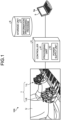
- FIG. 1 is a diagram illustrating a schematic configuration example of an information processing device according to an embodiment.
- a user of an information processing device 100 is referred to as a user U in the drawing.
- the drawing mainly illustrates the fingers (hands and fingers) and their surroundings in the body of the user U.
- the information processing device 100 is used for piano performance training of the user U.
- the exoskeleton robot 1 is worn on the hands of the user U.
- the exoskeleton robot 1 includes an exoskeleton robot 1-L and an exoskeleton robot 1-R.
- the exoskeleton robot 1-L is worn on the left hand of the user U.
- the exoskeleton robot 1-R is worn on the right hand of the user U.
- the exoskeleton robot 1-L and the exoskeleton robot 1-R may be simply referred to as an exoskeleton robot 1.
- the palm module 10 is a module for attaching the exoskeleton robot 1 to a hand of the user U.
- the palm module 10 is fixed to the hand of the user U in such a manner as to fit the back of the hand of the user U. Further details of the palm module 10 will be described later.
- FIGS. 5 and 6 are diagrams illustrating examples of customization of the exoskeleton robot.
- the finger joint module 20-2 to the finger joint module 20-5 only the finger joint module 20-2 is configured to have a driving function.
- the motor MT is mounted only on the finger joint module 20-2 among the finger joint module 20-2 to the finger joint module 20-5.
- the finger joint module 20-3 to the finger joint module 20-5 may be configured to have a sensing function.
- a sensor such as an angle sensor that detects the movement of the fingertip module 30-3 may be mounted on the finger joint module 20-3. The same applies to the fingertip module 30-4 and the finger joint module 20-4.
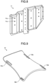
- FIG. 7 is a diagram illustrating an example of a schematic configuration of the palm module.
- the palm module 10 includes a first fixing unit 11 and a second fixing unit 12.
- the first fixing unit 11 is a portion to which the finger joint module 20 is fixed.
- the first fixing unit 11 is formed to have a shape suitable for attaching the finger joint module 20, for example.
- the second fixing unit 12 is a portion for fixing the palm module 10 to the hand of the user U.
- the second fixing unit 12 extends along the back of the hand of the user U.
- the second fixing unit 12 is a portion that comes into contact with the back of the hand of the user U and is formed to have a shape that fits the back of the hand of the user U, for example.
- FIG. 9 is a diagram illustrating an example of a schematic configuration of the second fixing unit of the palm module.
- the second fixing unit 12 has a curved surface smoothly defined along the back of the hand of the user U.
- the second fixing unit 12 has a rounded shape in the vicinity of the wrist such that no excessive pressure is applied to the wrist during dorsiflexion of the wrist.
- the second fixing unit 12 has a pair of slit holes 12a and 12a and a pair of slit holes 12b and 12b. Bands for fixing the relative position between the palm module 10 and the hand of the user U are attached (inserted or other means) to the slit holes 12a and the slit holes 12b. Note that, in this example, the width of one slit hole 12b of the pair of slit holes 12b and 12b is smaller than the width of the other slit hole 12b.
- FIGS. 10 and 11 are diagrams illustrating an example of fixing of the palm module by the bands.
- a band inserted through the slit holes 12a of the palm module 10 is referred to as a band 13a in the drawing.
- a band inserted through the slit holes 12b is referred to as a band 13b in the drawing.
- a specific example of the band 13a and the band 13b is a Velcro strap (Velcro is a registered trademark) or the like.
- the band 13a extends from the second fixing unit 12 in such a manner as to surround the wrist of the user U.
- the width of a portion of the band 13b passing between the interdigital region and the thenar of the user U may be narrower than the width of other portions.
- the band 13b includes a first portion 13b1 and a second portion 13b2.
- the first portion 13b1 passes between the interdigital region of the index finger and the thenar.
- the width of the first portion 13b1 is narrower than the width of the second portion 13b2, whereby the band 13b can extend while simultaneously avoiding the interdigital region of the index finger and the thenar.
- the robustness of the band 13b can be enhanced and the safety and the like can be improved as compared with a case where the width of the entire band 13b is made narrow like the width of the first portion 13b1.
- the first portion 13b1 out of the first portion 13b1 and the second portion 13b2 is attached to the slit hole 12b having the smaller width out of the pair of slit holes 12b and 12b.
- the second fixing unit 12 is fixed to the hand of the user U by the band 13a and the band 13b. For example, rotation indicated by an arrow AR1 or AR2 in FIG. 10 is suppressed.
- the arrow AR1 indicates rotation about a left-right direction axis, indicated by a broken line, as a rotation axis.
- a force in this rotation direction is mainly generated when the fingers are moved. If the fixation of the palm module 10 is not sufficient, the force and rotation angle required to move the fingers are consumed by rotation of the exoskeleton robot 1, which may lead to a possibility that the force to move the fingers cannot be sufficiently propagated or that the fingers cannot be moved by a sufficient angle. Fixing the palm module 10 securely with the bands 13a and 13b can address such issues.
- the palm module 10 can be securely fixed to the hand of the user U. Stable wearing of the palm module 10 can contribute to provision of appropriate training. For example, it is possible to cope with an issue that the exoskeleton robot 1 moves around during motions and that the training effect is weakened due to generation of a gap between the palm module 10 and the palm. An issue that fingers interfere with the palm module 10 during training to inhibit motions can also be addressed.
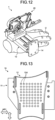
- FIG. 12 is a diagram illustrating an example of the jig.
- the palm module 10 is fixed to a jig 14, whereby the relative position between the palm module 10 and the user U is fixed.
- a mode of fixing the palm module 10 to the jig 14 is not particularly limited.
- the palm module 10 can be spatially fixed to the jig 14.
- the first fixing unit 11 and the second fixing unit 12 may be integrally formed or may be separately formed. In a case where the first fixing unit 11 and the second fixing unit 12 are integrally formed, the rigidity, the space, and the like can be easily secured. In a case where the first fixing unit 11 and the second fixing unit 12 are separately formed, it is possible to adjust the relative positions of the first fixing unit and the second fixing unit. This will be described with reference to FIGS. 13 and 14 .
- FIGS. 13 and 14 are diagrams illustrating an example of a schematic configuration of the palm module.
- the first fixing unit 11 and the second fixing unit 12 of the palm module 10 are separately formed and fixed (coupled, etc.) in such a manner that their relative positions are adjustable.
- the second fixing unit 12 has a plurality of connecting holes 12d arranged in a lattice pattern.
- the second fixing unit 12 is screwed to the first fixing unit 11 via any connecting holes 12d among the plurality of connecting holes 12d.
- the relative position of the first fixing unit 11 and the second fixing unit 12 can be adjusted at arrangement intervals.
- an adjustment block 15 for adjusting the relative position of the first fixing unit 11 and the second fixing unit 12 is provided between the first fixing unit 11 and the second fixing unit 12.
- the adjustment block 15 includes a first adjustment block 151, a second adjustment block 152, an adjustment screw 15a, and an adjustment screw 15b.
- the first adjustment block 151 is fixed to the bottom surface of the first fixing unit 11.
- the second adjustment block 152 is fixed to the top surface of the second fixing unit 12.
- the first adjustment block 151 and the second adjustment block 152 are configured to be connectable in such a manner as to be able to be positioned relative to each other.
- the relative position of the first adjustment block 151 and the second adjustment block 152 are adjusted by the adjustment screw 15a and the adjustment screw 15b.
- the relative position in the front-rear direction is adjusted by rotating the adjustment screw 15a.
- the relative position in the left-right direction is adjusted by rotating the adjustment screw 15b.
- the palm module 10 can be easily fitted to the shape of the hand of the user U. This increases the possibility of improving the wearability of the exoskeleton robot 1 or improving the operability when the exoskeleton robot 1 is worn.
- the first fixing unit 11 and the second fixing unit 12 of various shapes may be combined.
- a first fixing unit 11 having a shape suitable for the number and the type of modules of the finger joint module 20 may be selected.
- a second fixing unit 12 having a shape conforming to the size and the shape of the hand that can vary depending on the age (adult, child, etc.), the sex, and others of the user U may be selected.
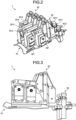
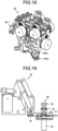
- FIGS. 15 to 18 are diagrams illustrating an example of a schematic configuration of a finger joint module.
- a finger joint module 20 includes a mechanism MV.
- the mechanism MV moves finger joints of the user U, for example, via a corresponding fingertip module 30. Examples of the joint include the DIP joint, the PIP joint, the MP joint, and the CM joint.
- the mechanism MV illustrated in the drawing is a parallel link mechanism.
- the mechanism MV may be an RCM mechanism configured to have a remote center of motion (RCM) at a finger joint of the user U.
- RCM remote center of motion
- the exoskeleton robot 1 can be attached to the finger without hindering the motion of the finger.
- a variety of finger joint modules 20 may be selectively employed, and some examples are illustrated in FIGS. 15 through 18 .
- the finger joint module 20 has a driving function, and more specifically includes a motor MT so as to have one degree of freedom.
- the motor MT may be a servo motor, and the finger joint module 20 in this case can also be referred to as a one-degree-of-freedom servo module.
- the finger joint module 20 moves a corresponding fingertip module 30 in the up-down direction.
- the finger of the user U can be moved to perform a keystroke operation.
- the finger joint module 20 includes a sensor such as an angle sensor in such a manner as to have a sensing function.
- the sensor is referred to as a sensor S in the drawing.
- the finger joint module 20 may not include the motor MT, and the weight of the finger joint module 20 can be reduced accordingly.
- the finger joint module 20-1 includes a shaft 20a and a shaft 20b, each supporting a different degree of freedom.
- the shaft 20a and the shaft 20b extend in such a manner as to bypass the thumb.
- the motor MT is not limited to a servo motor.
- a configuration capable of direct driving by a brushless motor or the like may be adopted in order to ensure more transparency.
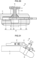
- FIGS. 19 to 22 are diagrams illustrating an example of a schematic configuration of a fingertip module. Note that FIG. 22 is a cross-sectional view when viewed in the front-rear direction.
- a fingertip module 30 includes a body 31, an attachment member 32, a band 33, a holder 34, and an adjustment screw 35.
- the body 31 extends along the finger of the user U. In this example, the body 31 extends along the proximal portion of the finger.
- the attachment member 32 detachably attaches the end of the body 31 on a finger joint module 20 side to the finger joint module 20.
- the body 31 has a rotational degrees of freedom with the up-down direction axis of the attachment member 32 as the rotation axis. This rotation corresponds to motions of the finger in and out.
- the attachment member 32 is a stepped screw. Fixation between the finger joint module 20 and the fingertip module 30 as well as shaft fixation that secures a minimum necessary gap for smooth motions are implemented by one simple member.
- the finger joint module 20 and the fingertip module 30 can be fixed to each other or released.
- the band 33 is held by the holder 34 and extends from the body 31 in such a manner as to cover a part of the finger of the user U, in this example, the proximal portion of the finger. As a result, the fingertip module 30 is fixed to the finger of the user U.
- the material of the band 33 is not particularly limited. For example, a material having elasticity and capable of providing a high frictional force with the finger of the user U may be used. Examples of such materials include resins such as silicone and rubber.
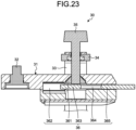
- FIG. 23 is a diagram illustrating an example of the release mechanism.
- the release mechanism included in the fingertip module 30 is referred to as a release mechanism 36 in the drawing.
- the release mechanism 36 moves the adjustment screw 35 such that the distance between the holder 34 and the body 31 decreases.
- the release mechanism 36 includes a cone 361, a spring 362, an abutment unit 363, a gap 364, and a release lever 365.
- the spring 362, the abutment unit 363, the gap 364, and the release lever 365 are included in this order towards the front.
- the abutment unit 363, the gap 364, and the release lever 365 may be integrally formed.
- the abutment unit 363, the gap 364, and the release lever 365 may be collectively referred to as the release lever 365 and the others.
- At least a part of the release lever 365 is exposed to the outside of the body 31.
- the state in which the abutment unit 363 is positioned below the adjustment screw 35 is switched to the state in which the gap 364 is positioned below the adjustment screw 35.
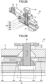
- the adjustment screw 35 moves forward, and the tightening by the band 33 is loosened (released) at once. This will be specifically described with reference to FIGS. 24 to 30 .
- the fingertip module 30 By fixing the fingertip module 30 to the distal portion, it is possible to directly apply a force to the fingertip and to move the fingertip as compared with, for example, a case where the fingertip module 30 is fixed to the proximal portion. For this reason, the movement of the fingertip can be easily controlled. It can be suitably used for experiment tasks or training focusing on the fingertips.
- a vibrator or the like may be provided instead of or together with the sensor S as described above. Tactile stimulation can be given to the fingertip.
- the controller 4 controls the exoskeleton robot 1.
- the control of the exoskeleton robot 1 by the controller 4 includes control such as driving (movement amount, angle, etc.) of the fingertip module 30 by the finger joint module 20.
- a control command generated by the terminal device 5 is transmitted from the terminal device 5 to the controller 4, and then from the controller 4 to the exoskeleton robot 1, whereby the exoskeleton robot 1 is controlled.
- the controller 4 is configured to be communicable with the exoskeleton robot 1 and the terminal device 5.
- An example of the communication between the controller 4 and the exoskeleton robot 1 is serial communication or the like and may be performed, for example, for each finger joint module 20 in the exoskeleton robot 1.
- FIG. 1 functional blocks of the controller 4 are also illustrated.
- the controller 4 includes a processing unit 41 and a power supply unit 42.
- the processing unit 41 includes a microcontroller and others. Processing by the processing unit 41 includes transmission of a control command from the controller 4 to the exoskeleton robot 1, more specifically, from the controller 4 to each finger joint module 20.
- a finger joint module 20 drives a fingertip module 30 in accordance with the control command.
- an ID may be assigned to each of the finger joint modules 20 of the exoskeleton robot 1.
- the control command is transmitted to a finger joint module 20 of a corresponding ID.
- the processing by the processing unit 41 includes generation of an operation log of the exoskeleton robot 1. For example, an operation result of each finger joint module 20 of the exoskeleton robot 1 is transmitted from the finger joint module 20 to the controller 4. An operation log describing the operation results is generated by the processing unit 41 and transmitted from the controller 4 to the terminal device 5.
- the power supply unit 42 functions as a power supply of the exoskeleton robot 1.
- the power supply unit 42 generates, for example, a voltage or a current suitable for the operation of the exoskeleton robot 1, more specifically, the operation of the finger joint module 20, and supplies the voltage or the current to the exoskeleton robot 1.
- the terminal device 5 is communicably connected to the controller 4. Examples of communication include universal serial bus (USB) communication, Ethernet (registered trademark) communication, and Bluetooth (registered trademark) communication.
- the terminal device 5 may be implemented using a general-purpose computer such as a PC. For example, the terminal device 5 generates the above-described control command and transmits the control command to the exoskeleton robot 1 via the controller 4. In addition, the terminal device 5 collects the operation log of the exoskeleton robot 1 via the controller 4.
- Control commands for controlling the finger joint modules 20 may be collectively generated on the terminal device 5 and transmitted from the terminal device 5 to the controller 4.
- the control commands collectively generated here include information of the IDs of the finger joint modules 20.
- the controller 4 separates the control commands from the terminal device 5 into control commands for respective finger joint modules 20 on the basis of the IDs and transmits the control commands to the corresponding finger joint modules 20.
- control commands are collectively transmitted from the terminal device 5 to the controller 4, and the controller 4 transmits the control commands to the respective finger joint modules 20, whereby synchronization among the modules can be enhanced.
- including an ID in a control command makes it possible, basically, not to perform ID management in the controller 4. This allows the single controller 4 to be used for various exoskeleton robots 1.
- Step S1 the terminal device 5 generates control commands.
- the control commands including IDs of respective finger joint modules 20 are collectively generated on the terminal device 5.
- the generated control commands are transmitted from the terminal device 5 to the controller 4.
- Step S2 the controller 4 separates a control command for each of the finger joint modules 20.
- the separated control commands are transmitted from the controller 4 to the corresponding finger joint modules 20.
- Step S4 the controller 4 collects the results.
- An operation log describing the operation results of the finger joint modules 20 is generated and transmitted from the controller 4 to the terminal device 5.
- the exoskeleton robot 1 is controlled as described above, for example.
- FIGS. 34 and 35 are diagrams illustrating an example of generation of a control command.
- a screen for generating a control command is displayed on a display unit 5a of the terminal device 5.
- the control command is illustrated in a graph form and is generated by a user operation.
- the horizontal axis of the graph indicates time, and the vertical axis indicates the movement amount of the fingers.
- An item “thumb-x” and “thumb-y” in the vertical axis indicate the movement amount on one axis and the movement amount on the other axis of biaxial movement (up-down movement and horizontal movement) of the thumb, respectively.
- An item “index” indicates the movement amount of one-axis movement (up-down movement) of the index finger.
- An item “middle” indicates the movement amount of one-axis movement of the middle finger.
- An item “ring” indicates the movement amount of one-axis movement of the ring finger.
- An item “little” indicates the movement amount of one-axis movement of the little finger.
- control commands are generated by actively moving the exoskeleton robot 1 and editing the recorded data.
- a piano player or the like wears the exoskeleton robot 1 or a similar device, on which sensors S for detecting the movement amount of the fingers are mounted, and plays the piano.
- Selecting "Rec” causes the sensor results at the time of performance, namely, the movement amount of the fingers to be recorded, and control commands for reproducing the movement amounts are generated.
- Selecting "Play” makes it possible to confirm the content of the performance or to change the speed of the performance.
- the control commands may be generated using a GUI as illustrated in FIG. 34 .
- the control commands are generated from scratch by a user operation.
- a portion (node) where the movement amount of a finger changes is manually generated.
- a node is defined by dragging a start position or an end position of a node or specifying a numerical value.
- a dialog of a selected node may be displayed, whereby confirmation, setting, and the like of numerical values may be performed.
- An operation of adding a node by clicking a portion free from nodes may also be performed. Selecting "Simulate" makes it possible to confirm the content of the performance, and specifying a value for Repeat makes it possible to loop the performance or to determine the total performance time.
- the control commands may be generated using a GUI as illustrated in FIG. 35 .
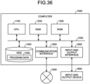
- FIG. 36 is a diagram illustrating an example of the hardware configuration.
- the information processing device 100(the controller 4, the terminal device 5, and the like) described above can include a computer 1000 as illustrated in FIG. 36 , for example.
- the ROM 1300 stores a boot program such as a basic input output system (BIOS) executed by the CPU 1100 when the computer 1000 is activated, a program dependent on the hardware of the computer 1000, and the like.
- BIOS basic input output system
- the information processing device 100 includes the exoskeleton robot 1 worn on the hand of the user and the controller 4 that controls the exoskeleton robot 1.
- the exoskeleton robot 1 includes the palm module 10 fixed to the hand of the user U, the finger joint module 20 detachably attached to the palm module 10, and the fingertip module 30 detachably attached to the finger joint module 20 and fixed to a finger of the user U.
- the finger joint module 20 is configured to have at least one of the function of driving the fingertip module 30 or the function of sensing the fingertip module 30.
- the palm module 10 may include the first fixing unit 11 to which the finger joint module 20 is fixed and the second fixing unit 12 that extends along the back of the hand of the user U and fixes the palm module 10 to the hand of the user U.
- the palm module 10 can be fixed in such a manner as to fit the hand of the user U.
- the palm module 10 includes the band 13b extending from the second fixing unit 12 in such a manner as to cover a portion of the palm of the user U, and the part of the palm of the user U may not include the interdigital region or the thenar. This can prevent the band 13b from hindering movement of the fingers.
- the first fixing unit 11 and the second fixing unit 12 may be fixed in such a manner that the relative position thereof can be adjusted.
- the palm module 10 can be easily fitted to the shape of the hand of the user U.
- this increases the possibility of improving the wearability of the exoskeleton robot 1 or improving the operability when the exoskeleton robot 1 is worn.
- the finger joint module 20-1 may include two RCM mechanisms (the mechanism MVa and the mechanism MVb) each having a center of rotation at a joint of the thumb of the user U.
- the exoskeleton robot 1 can be configured to include various finger joint modules 20 in this manner, for example.
- the fingertip module 30 may include the body 31 extending along the finger of the user U and the band 33 extending from the body 31 in such a manner as to cover a portion of the finger of the user U.
- the fingertip module 30 may include the holder 34 that holds the band 33 and the adjustment screw 35 that adjusts the distance between the holder 34 and the body 31, the holder 34 and the body 31 arranged on the side opposite to the finger of the user U with the body 31 interposed therebetween.
- the fingertip module 30 can be appropriately fixed to the finger of the user U in this manner, for example.
- the fingertip module 30 may include the release mechanism 36 that moves the adjustment screw 35 such that the distance between the holder 34 and the body 31 decreases
- the release mechanism 36 may include: the abutment unit 363 that is movable in the direction (for example, the front-rear direction) intersecting the traveling direction of the adjustment screw 35 in such a manner as to abut on the tip of the adjustment screw 35 when located ahead of (for example, below) the adjustment screw 35 in the traveling direction; and the gap 364 that is movable in the direction intersecting the traveling direction of the adjustment screw 35 such that the adjustment screw 35 passes therethrough when located ahead of the adjustment screw 35 in the traveling direction.
- the information processing device 100 may include the plurality of exoskeleton robots 1(for example, the exoskeleton robot 1-L and the exoskeleton robot 1-R) and one controller 4 that controls the plurality of exoskeleton robots 1. This facilitates synchronous operation of the plurality of exoskeleton robots 1.
- the information processing device 100 includes the terminal device 5 that generates control commands for controlling the exoskeleton robot 1, and the controller 4 may transmit the control commands generated by the terminal device 5 to the exoskeleton robot 1.
- the finger joint module 20 may include a plurality of finger joint modules 20 (for example, the finger joint module 20-1 to the finger joint module 20-5) corresponding to different fingers, the terminal device 5 may collectively generate control commands for the respective finger joint modules 20, and the controller 4 may separate the control commands collectively generated by the terminal device 5 into control commands for the respective finger joint modules 20 and transmit the control commands to corresponding finger joint modules 20.
- the exoskeleton robot 1 can be controlled in this manner, for example.
- the information processing method described with reference to FIGS. 1 to 6 , 33, and others is also one piece of the disclosed technique.
- the information processing method includes controlling the exoskeleton robot 1 worn on the hand of the user U (for example, Steps S1 to S5).
- the exoskeleton robot 1 is as described above. Also by such an information processing method, as described above, it is possible to provide training by the exoskeleton robot 1 having an appropriate configuration corresponding to the application.
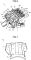
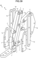
- FIGS. 37 to 41 are diagrams illustrating an example of a schematic configuration of a finger joint module.
- a finger joint module 20 that is illustrated has an RCM link mechanism as a basic structure as described above. This link mechanism is referred to as a link mechanism 8 in the drawing.
- the link mechanism 8 includes a plurality of links L (nodes) and joints J (shafts) that connect (couple) the links L.
- a joint J may be a shaft, a pin, or the like.
- FIGS. 37 to 39 some resin links L R and metal links L M are illustrated together with their reference numerals.
- a pair of metal links L M is arranged in such a manner as to sandwich a resin link L R .
- These metal links L M and the resin link L R are connected by joints J.
- the metal links L M on the outer side and the joints J are press-fitted and fixed such that the joints J do not come off.
- a bearing is inserted between a joint J and a link L.
- the plurality of links L may include only the resin links L R or only the metal links L M .
- the joints J and the links L may not be press-fitted and fixed, and in that case, for example, a hinge pin with a stopper or a combination of a collar and a screw may be used. Furthermore, there is no need to insert a bearing between a joint J and a link L.
- a finger joint module 20 includes a sensor S so as to have a sensing function. In this example, it is based on the premise that the sensor S is an angle sensor.
- the rotation axis of the motor MT (an example of an actuator) described above and an extension line thereof are schematically illustrated by an alternate long and short dash line.
- the sensor S is fixed on the rotation axis of the motor MT.
- the sensor S is disposed and fixed such that the extension line of the rotation axis passes through the central part of the sensor S. This makes it possible to stably and accurately detect (measure) angle information.
- the senor S may be arranged at various positions without being limited to the above position so as to be able to detect the angle of any joint J.
- the finger joint module 20-1 corresponding to the thumb will be further described.
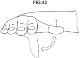
- the motion of the thumb includes two types of motions: abduction motion and adduction motion (abduction and adduction motions) starting from the CM joint; and bending motion and extending motion (bending and extending motions) of each of the CM joint and the MP joint. This will be described with reference to FIGS. 42 and 43 .
- FIG. 42 is a diagram illustrating an example of abduction and adduction motions of the thumb.
- the thumb of the user U rotates (abduction) in such a manner as to be separated from the palm or rotates (adduction) in such a manner as to approach the palm with the CM joint as a starting point.
- the thumb after abduction is drawn by a solid line
- the thumb after adduction is drawn by an alternate long and short dash line.
- the abduction and adduction motions are given by disposing the motor MT such that the CM joint of the thumb of the user U is located on the extension line (alternate long and short dash line) of the rotation axis of the motor MT (the extension line passes through the CM joint).
- the thumb is abducted or adducted depending on the rotation of the motor MT.
- the link mechanism 8 of the finger joint module 20-1 has a structure in which the bending and extending motions of the CM joint and the MP joint are simultaneously cooperatively driven by one motor MT.
- FIGS. 45 and 46 are diagrams illustrating an example of the bending and extending motions by the link mechanism.
- the link mechanism 8 has a center of rotation at the MP joint of the thumb of the user U. This gives bending and extending motions of the MP joint of the thumb.
- the bending and extending motions of the CM joint is regarded as a linear motion.
- the entire link mechanism 8 moves linearly.
- the link mechanism 8 slides and linearly moves as indicated by a hollow arrow. In this manner, bending and extending motions of both the CM and MP joints are given. This will be further described with reference to FIGS. 47 to 50 .
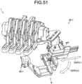
- FIGS. 47 and 48 are diagrams illustrating an example of the schematic configuration of the finger joint module corresponding to the thumb.
- the finger joint module 20-1 corresponding to the thumb includes the linear movement mechanism 7, the motor MT, and the link mechanism 8.
- the support unit 71 supports the link mechanism 8.
- a base portion of the link mechanism 8 (portions of a joint J1 and a joint J2 to be described later) is fixed to the support unit 71.
- the movement unit 72 moves the support unit 71, more specifically, moves the support unit 71 relatively to the base unit 73.
- the movement of the support unit 71 corresponds to the linear movement of the link mechanism 8 described above.
- the movement unit 72 moves the support unit 71 by sliding the support unit 71.
- the movement unit 72 includes a first portion 721 and a second portion 722.
- the support unit 71 is fixed to the first portion 721.
- the second portion 722 is fixed to the base unit 73.
- the first portion 721 is slidable with respect to the second portion 722.
- Various known slide mechanisms may be used.
- the link L13 is a first link having a first end connected to the joint J1, and more specifically, is connected between the joint J1 and the joint J3.
- the link L25 is a second link having a first end connected to the joint J2, and more specifically, is connected between the joint J2 and the joint J5, and is also connected to the joint J4 at a position therebetween (position in the middle).
- the link L37 is connected between the joint J3 and the joint J7 and is also connected to the joint J4 at a position therebetween (position in the middle).
- each link L of the link mechanism 8 and the entire link mechanism 8 are at the initial position.
- the motor MT rotates
- the joint J1 and the joint J2 are rotationally driven, and each link L of the link mechanism 8 moves as illustrated in FIG. 48 .
- the movement unit 72 of the linear movement mechanism 7 slides, and the entire link mechanism 8 moves linearly.
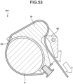
- FIGS. 52 and 53 are diagrams illustrating an example of a schematic configuration of the fingertip module corresponding to the thumb.
- the fingertip module 30-1 includes a base 91, a lever 92, and a band 93 (also referred to as a belt) in addition to the body 31 and the attachment member 32 described above.
- the operation of fixing or removing the fingertip module 30 to or from the thumb of the user U is smoothly performed by the base 91, the lever 92, and the band 93.
- the basic principle is similar to that of a lashing belt used for fixing a cargo bed of a vehicle, camping, or others.
- the finger joint module 20-1 includes the motor MT and the link mechanism 8 operated by the rotation of the motor MT so as to have three degrees of freedom
- the motor MT is disposed such that the CM joint of the thumb is located on the extension line of the rotation axis in order to give the abduction motion and the adduction motion starting from the CM joint of the thumb
- the link mechanism 8 has the center of rotation at the MP joint of the thumb in order to give the bending motion and the extending motion of the MP joint of the thumb
- the link mechanism 8 may entirely move linearly in order to give the bending motion and the extending motion of the CM joint of the thumb.
- the three degrees of freedom can be obtained in this manner, for example.
- the finger joint module 20-1 may include the linear movement mechanism 7, the linear movement mechanism 7 may include the base unit 70 including the motor MT, the support unit 71 that supports the link mechanism 8, and the movement unit 72 that linearly moves the support unit 71 relatively to the base unit 70, the link mechanism 8 may operate to give the bending motion and the extending motion of the MP joint of the thumb as the motor MT rotates, and the link mechanism 8 may linearly move to give the bending motion and the extending motion of the CM joint of the thumb as the support unit 81 linearly moves by the movement unit 72.
- two types of motions can be given by only one motor MT, and these motions can be controlled.
- the link mechanism 8 may include, in order for the movement unit 72 of the linear movement mechanism 7 linearly moves the support unit 71 as the motor MT rotates, the joint J1 (first joint) and the joint J2 (second joint) rotationally driven by the motor MT, the joint J1 and the joint J2 included in the support unit 71 of the linear movement mechanism 7, the link L13 (first link) having the first end connected to the joint J1, the link L25 (second link) having the first end connected to the joint J2, the joint J3 (third joint) to which a second end of the link L13 is connected, and the additional links (the link L38 and the link L89) connected between the joint J3 (third joint) and the base unit 70 of the linear movement mechanism 7.
- the linear movement mechanism 7 and the link mechanism 8 as described above, it is possible to synchronize two types of motions of the abduction and adduction motions and the bending and extending motions.
Landscapes
- Engineering & Computer Science (AREA)
- Physics & Mathematics (AREA)
- Theoretical Computer Science (AREA)
- General Engineering & Computer Science (AREA)
- Multimedia (AREA)
- General Physics & Mathematics (AREA)
- Robotics (AREA)
- Mechanical Engineering (AREA)
- Acoustics & Sound (AREA)
- Human Computer Interaction (AREA)
- Business, Economics & Management (AREA)
- Educational Administration (AREA)
- Educational Technology (AREA)
- Health & Medical Sciences (AREA)
- General Health & Medical Sciences (AREA)
- Physical Education & Sports Medicine (AREA)
- Prostheses (AREA)
- Rehabilitation Tools (AREA)
Applications Claiming Priority (2)
| Application Number | Priority Date | Filing Date | Title |
|---|---|---|---|
| JP2022090478 | 2022-06-02 | ||
| PCT/JP2023/019652 WO2023234197A1 (ja) | 2022-06-02 | 2023-05-26 | 情報処理装置、情報処理方法及び情報処理プログラム |
Publications (2)
| Publication Number | Publication Date |
|---|---|
| EP4535334A1 true EP4535334A1 (de) | 2025-04-09 |
| EP4535334A4 EP4535334A4 (de) | 2025-04-23 |
Family
ID=89024952
Family Applications (1)
| Application Number | Title | Priority Date | Filing Date |
|---|---|---|---|
| EP23815954.5A Pending EP4535334A4 (de) | 2022-06-02 | 2023-05-26 | Informationsverarbeitungsvorrichtung, informationsverarbeitungsverfahren und informationsverarbeitungsprogramm |
Country Status (4)
| Country | Link |
|---|---|
| US (1) | US20250329270A1 (de) |
| EP (1) | EP4535334A4 (de) |
| JP (1) | JPWO2023234197A1 (de) |
| WO (1) | WO2023234197A1 (de) |
Family Cites Families (30)
| Publication number | Priority date | Publication date | Assignee | Title |
|---|---|---|---|---|
| US4986280A (en) * | 1988-07-20 | 1991-01-22 | Arthur D. Little, Inc. | Hand position/measurement control system |
| IT1264718B1 (it) * | 1993-10-08 | 1996-10-04 | Scuola Superiore Di Studi Universitari E Di Perfezionamento Sant Anna | Dispositivo atto a fornire una retroazione di forza ad un'unita' fisiologica, da utilizzarsi in particolare come interfaccia avanzata |
| JP3409160B2 (ja) * | 2000-04-26 | 2003-05-26 | 独立行政法人産業技術総合研究所 | 把握データ入力装置 |
| JP3624374B2 (ja) * | 2000-12-12 | 2005-03-02 | 独立行政法人産業技術総合研究所 | 力覚呈示装置 |
| WO2006063347A2 (en) * | 2004-12-10 | 2006-06-15 | Saebo, Inc. | Dynamic hand splints |
| US8574178B2 (en) * | 2009-05-26 | 2013-11-05 | The Hong Kong Polytechnic University | Wearable power assistive device for helping a user to move their hand |
| JP5725603B2 (ja) * | 2010-12-17 | 2015-05-27 | 国立大学法人岐阜大学 | 側面設置型力覚提示インターフェイス |
| WO2015095459A1 (en) * | 2013-12-18 | 2015-06-25 | Board Of Regents, The University Of Texas System | Robotic finger exoskeleton |
| US10423227B2 (en) * | 2014-07-21 | 2019-09-24 | Dexta Robotics | Hand exoskeleton force feedback system |
| US10817056B2 (en) * | 2014-07-21 | 2020-10-27 | Shenzhen Dexta Robotics Co. Ltd. | Hand exoskeleton force feedback system |
| JP2016083000A (ja) * | 2014-10-23 | 2016-05-19 | セイコーエプソン株式会社 | 駆動装置、指関節駆動装置、及び、駆動方法 |
| EP3226824B1 (de) * | 2014-12-04 | 2019-06-19 | Telerobot Labs S.r.l. | Hilfsvorrichtung zur bewegung und/oder rehabilitation von einem oder mehreren fingern einer hand |
| JP6279143B2 (ja) * | 2015-02-24 | 2018-02-14 | 圭治郎 山本 | 関節運動アシスト装置及び当該関節運動アシスト装置の装着方法 |
| US20180335841A1 (en) * | 2017-05-19 | 2018-11-22 | Axonvr Corporation | Haptic feedback glove |
| US20180335842A1 (en) * | 2017-05-19 | 2018-11-22 | Axonvr Corporation | Haptic feedback glove |
| CA3079691A1 (en) * | 2017-11-07 | 2019-05-16 | Ecole Polytechnique Federale De Lausanne (Efpl) | Hand exoskeleton device |
| US11508344B2 (en) * | 2017-12-27 | 2022-11-22 | Sony Corporation | Information processing device, information processing method and program |
| WO2020100671A1 (ja) * | 2018-11-15 | 2020-05-22 | ソニー株式会社 | 情報処理装置、情報処理方法及びプログラム |
| CN110695971A (zh) * | 2019-10-24 | 2020-01-17 | 广东技术师范大学 | 一种外骨骼机械辅助手 |
| EP4057211A4 (de) * | 2019-11-07 | 2022-11-23 | Sony Group Corporation | Informationsverarbeitungsvorrichtung, informationsverarbeitungsverfahren und programm |
| JP7103703B2 (ja) * | 2020-02-06 | 2022-07-20 | 株式会社メルティンMmi | 動作補助装置 |
| WO2021172580A1 (ja) * | 2020-02-27 | 2021-09-02 | 学校法人慶應義塾 | 位置・力制御システム、装着ユニット、制御ユニット、位置・力制御方法及びプログラム |
| WO2021182264A1 (ja) * | 2020-03-11 | 2021-09-16 | ソニーグループ株式会社 | 情報処理装置、情報処理方法及び情報処理プログラム |
| US12569392B2 (en) * | 2020-04-22 | 2026-03-10 | Virginia Tech Intellectual Properties, Inc. | Intelligent hand exoskeleton with grasping assistance |
| JP7709171B2 (ja) * | 2020-04-23 | 2025-07-16 | 慶應義塾 | 指動作補助装置 |
| CN111643315B (zh) * | 2020-04-27 | 2021-09-03 | 东南大学 | 一种基于绳索驱动的柔性手部功能康复装置 |
| WO2022201922A1 (ja) * | 2021-03-25 | 2022-09-29 | ソニーグループ株式会社 | 情報処理装置、情報処理方法及び情報処理システム |
| CA3217976A1 (en) * | 2021-05-03 | 2022-11-10 | Mark A. Salada | Haptic hand controller system for mixed reality |
| US12608082B2 (en) * | 2021-07-07 | 2026-04-21 | Sam Drucker | Wearable hand interface device and methods |
| JPWO2023127078A1 (de) * | 2021-12-28 | 2023-07-06 |
-
2023
- 2023-05-26 EP EP23815954.5A patent/EP4535334A4/de active Pending
- 2023-05-26 WO PCT/JP2023/019652 patent/WO2023234197A1/ja not_active Ceased
- 2023-05-26 JP JP2024524814A patent/JPWO2023234197A1/ja active Pending
- 2023-05-26 US US18/864,280 patent/US20250329270A1/en active Pending
Also Published As
| Publication number | Publication date |
|---|---|
| JPWO2023234197A1 (de) | 2023-12-07 |
| EP4535334A4 (de) | 2025-04-23 |
| US20250329270A1 (en) | 2025-10-23 |
| WO2023234197A1 (ja) | 2023-12-07 |
Similar Documents
| Publication | Publication Date | Title |
|---|---|---|
| Fang et al. | Wireality: Enabling complex tangible geometries in virtual reality with worn multi-string haptics | |
| EP1876505B1 (de) | Schwerkraftausgleich für eine haptische Vorrichtung | |
| JP3290436B2 (ja) | 力フィードバック及びテクスチャー擬似インタフェース装置 | |
| EP2919948B1 (de) | Handsteuerungsvorrichtung | |
| JP5109573B2 (ja) | 制御システム及び制御方法、並びにロボット装置 | |
| Shi et al. | A cable-driven three-DOF wrist rehabilitation exoskeleton with improved performance | |
| US6979164B2 (en) | Force feedback and texture simulating interface device | |
| US6042555A (en) | Force-feedback interface device for the hand | |
| JP5406893B2 (ja) | 力および位置ベースの制御法則を用いたテンドン駆動ロボットフィンガのロバスト操作 | |
| JP2004213350A (ja) | 力覚提示装置及び画像補正方法 | |
| JP4085691B2 (ja) | 画像処理装置 | |
| EP4119308B1 (de) | Informationsverarbeitungsvorrichtung, informationsverarbeitungsverfahren und informationsverarbeitungsprogramm | |
| JP7103703B2 (ja) | 動作補助装置 | |
| EP4535334A1 (de) | Informationsverarbeitungsvorrichtung, informationsverarbeitungsverfahren und informationsverarbeitungsprogramm | |
| US20180014744A1 (en) | Motor-activated multi-functional wrist orthotic | |
| Speeter | Control of the Utah/MIT dextrous hand: Hardware and software hierarchy | |
| JPH05504430A (ja) | コンピュータシステムのための制御手段とそのような制御手段を有する表示装置 | |
| JPH04210393A (ja) | 手話ロボット | |
| JP2013508828A (ja) | ヒューマンマシンインタフェースデバイス | |
| JP2794087B2 (ja) | コンピュータ設計支援システム | |
| JP4487782B2 (ja) | 多関節ロボットに教示する動作データの作成装置と作成方法 | |
| JP2010271535A (ja) | 擦弦楽器演奏ロボット | |
| Harsha et al. | Design and development of 8-dof forearm rehabilitation device | |
| Wu et al. | Static prehension of a horizontally oriented object in three dimensions | |
| JP2004318399A (ja) | 画像処理装置及び触覚・力覚提示方法 |
Legal Events
| Date | Code | Title | Description |
|---|---|---|---|
| STAA | Information on the status of an ep patent application or granted ep patent |
Free format text: STATUS: THE INTERNATIONAL PUBLICATION HAS BEEN MADE |
|
| PUAI | Public reference made under article 153(3) epc to a published international application that has entered the european phase |
Free format text: ORIGINAL CODE: 0009012 |
|
| STAA | Information on the status of an ep patent application or granted ep patent |
Free format text: STATUS: REQUEST FOR EXAMINATION WAS MADE |
|
| 17P | Request for examination filed |
Effective date: 20250102 |
|
| AK | Designated contracting states |
Kind code of ref document: A1 Designated state(s): AL AT BE BG CH CY CZ DE DK EE ES FI FR GB GR HR HU IE IS IT LI LT LU LV MC ME MK MT NL NO PL PT RO RS SE SI SK SM TR |
|
| A4 | Supplementary search report drawn up and despatched |
Effective date: 20250326 |
|
| RIC1 | Information provided on ipc code assigned before grant |
Ipc: A61H 1/02 20060101ALI20250320BHEP Ipc: B25J 9/00 20060101ALI20250320BHEP Ipc: G10H 1/00 20060101ALI20250320BHEP Ipc: G10G 1/00 20060101ALI20250320BHEP Ipc: G06F 3/01 20060101ALI20250320BHEP Ipc: B25J 11/00 20060101ALI20250320BHEP Ipc: G09B 15/00 20060101AFI20250320BHEP |
|
| DAV | Request for validation of the european patent (deleted) | ||
| DAX | Request for extension of the european patent (deleted) | ||
| STAA | Information on the status of an ep patent application or granted ep patent |
Free format text: STATUS: EXAMINATION IS IN PROGRESS |
|
| 17Q | First examination report despatched |
Effective date: 20251016 |