EP4535477A2 - Vorrichtung und verfahren zur herstellung einer spule, vorzugsweise für eine elektrochemische zelle zur herstellung von batterien - Google Patents
Vorrichtung und verfahren zur herstellung einer spule, vorzugsweise für eine elektrochemische zelle zur herstellung von batterien Download PDFInfo
- Publication number
- EP4535477A2 EP4535477A2 EP24223214.8A EP24223214A EP4535477A2 EP 4535477 A2 EP4535477 A2 EP 4535477A2 EP 24223214 A EP24223214 A EP 24223214A EP 4535477 A2 EP4535477 A2 EP 4535477A2
- Authority
- EP
- European Patent Office
- Prior art keywords
- strip
- winding
- shaped article
- strips
- coil
- Prior art date
- Legal status (The legal status is an assumption and is not a legal conclusion. Google has not performed a legal analysis and makes no representation as to the accuracy of the status listed.)
- Pending
Links
Images




Classifications
-
- B—PERFORMING OPERATIONS; TRANSPORTING
- B21—MECHANICAL METAL-WORKING WITHOUT ESSENTIALLY REMOVING MATERIAL; PUNCHING METAL
- B21C—MANUFACTURE OF METAL SHEETS, WIRE, RODS, TUBES, PROFILES OR LIKE SEMI-MANUFACTURED PRODUCTS OTHERWISE THAN BY ROLLING; AUXILIARY OPERATIONS USED IN CONNECTION WITH METAL-WORKING WITHOUT ESSENTIALLY REMOVING MATERIAL
- B21C47/00—Winding-up, coiling or winding-off metal wire, metal band or other flexible metal material characterised by features relevant to metal processing only
- B21C47/02—Winding-up or coiling
-
- B—PERFORMING OPERATIONS; TRANSPORTING
- B21—MECHANICAL METAL-WORKING WITHOUT ESSENTIALLY REMOVING MATERIAL; PUNCHING METAL
- B21C—MANUFACTURE OF METAL SHEETS, WIRE, RODS, TUBES, PROFILES OR LIKE SEMI-MANUFACTURED PRODUCTS OTHERWISE THAN BY ROLLING; AUXILIARY OPERATIONS USED IN CONNECTION WITH METAL-WORKING WITHOUT ESSENTIALLY REMOVING MATERIAL
- B21C47/00—Winding-up, coiling or winding-off metal wire, metal band or other flexible metal material characterised by features relevant to metal processing only
- B21C47/02—Winding-up or coiling
- B21C47/04—Winding-up or coiling on or in reels or drums, without using a moving guide
-
- B—PERFORMING OPERATIONS; TRANSPORTING
- B21—MECHANICAL METAL-WORKING WITHOUT ESSENTIALLY REMOVING MATERIAL; PUNCHING METAL
- B21C—MANUFACTURE OF METAL SHEETS, WIRE, RODS, TUBES, PROFILES OR LIKE SEMI-MANUFACTURED PRODUCTS OTHERWISE THAN BY ROLLING; AUXILIARY OPERATIONS USED IN CONNECTION WITH METAL-WORKING WITHOUT ESSENTIALLY REMOVING MATERIAL
- B21C47/00—Winding-up, coiling or winding-off metal wire, metal band or other flexible metal material characterised by features relevant to metal processing only
- B21C47/24—Transferring coils to or from winding apparatus or to or from operative position therein; Preventing uncoiling during transfer
- B21C47/245—Devices for the replacement of full reels by empty reels or vice versa, without considerable loss of time
-
- B—PERFORMING OPERATIONS; TRANSPORTING
- B21—MECHANICAL METAL-WORKING WITHOUT ESSENTIALLY REMOVING MATERIAL; PUNCHING METAL
- B21C—MANUFACTURE OF METAL SHEETS, WIRE, RODS, TUBES, PROFILES OR LIKE SEMI-MANUFACTURED PRODUCTS OTHERWISE THAN BY ROLLING; AUXILIARY OPERATIONS USED IN CONNECTION WITH METAL-WORKING WITHOUT ESSENTIALLY REMOVING MATERIAL
- B21C47/00—Winding-up, coiling or winding-off metal wire, metal band or other flexible metal material characterised by features relevant to metal processing only
- B21C47/32—Tongs or gripping means specially adapted for reeling operations
-
- B—PERFORMING OPERATIONS; TRANSPORTING
- B21—MECHANICAL METAL-WORKING WITHOUT ESSENTIALLY REMOVING MATERIAL; PUNCHING METAL
- B21C—MANUFACTURE OF METAL SHEETS, WIRE, RODS, TUBES, PROFILES OR LIKE SEMI-MANUFACTURED PRODUCTS OTHERWISE THAN BY ROLLING; AUXILIARY OPERATIONS USED IN CONNECTION WITH METAL-WORKING WITHOUT ESSENTIALLY REMOVING MATERIAL
- B21C47/00—Winding-up, coiling or winding-off metal wire, metal band or other flexible metal material characterised by features relevant to metal processing only
- B21C47/34—Feeding or guiding devices not specially adapted to a particular type of apparatus
- B21C47/345—Feeding or guiding devices not specially adapted to a particular type of apparatus for monitoring the tension or advance of the material
-
- B—PERFORMING OPERATIONS; TRANSPORTING
- B65—CONVEYING; PACKING; STORING; HANDLING THIN OR FILAMENTARY MATERIAL
- B65H—HANDLING THIN OR FILAMENTARY MATERIAL, e.g. SHEETS, WEBS, CABLES
- B65H19/00—Changing the web roll
- B65H19/22—Changing the web roll in winding mechanisms or in connection with winding operations
- B65H19/2207—Changing the web roll in winding mechanisms or in connection with winding operations the web roll being driven by a winding mechanism of the centre or core drive type
- B65H19/2223—Turret-type with more than two roll supports
-
- B—PERFORMING OPERATIONS; TRANSPORTING
- B65—CONVEYING; PACKING; STORING; HANDLING THIN OR FILAMENTARY MATERIAL
- B65H—HANDLING THIN OR FILAMENTARY MATERIAL, e.g. SHEETS, WEBS, CABLES
- B65H19/00—Changing the web roll
- B65H19/22—Changing the web roll in winding mechanisms or in connection with winding operations
- B65H19/26—Cutting-off the web running to the wound web roll
-
- B—PERFORMING OPERATIONS; TRANSPORTING
- B65—CONVEYING; PACKING; STORING; HANDLING THIN OR FILAMENTARY MATERIAL
- B65H—HANDLING THIN OR FILAMENTARY MATERIAL, e.g. SHEETS, WEBS, CABLES
- B65H20/00—Advancing webs
- B65H20/30—Arrangements for accumulating surplus web
- B65H20/32—Arrangements for accumulating surplus web by making loops
- B65H20/34—Arrangements for accumulating surplus web by making loops with rollers
-
- B—PERFORMING OPERATIONS; TRANSPORTING
- B65—CONVEYING; PACKING; STORING; HANDLING THIN OR FILAMENTARY MATERIAL
- B65H—HANDLING THIN OR FILAMENTARY MATERIAL, e.g. SHEETS, WEBS, CABLES
- B65H23/00—Registering, tensioning, smoothing or guiding webs
- B65H23/04—Registering, tensioning, smoothing or guiding webs longitudinally
- B65H23/18—Registering, tensioning, smoothing or guiding webs longitudinally by controlling or regulating the web-advancing mechanism, e.g. mechanism acting on the running web
- B65H23/188—Registering, tensioning, smoothing or guiding webs longitudinally by controlling or regulating the web-advancing mechanism, e.g. mechanism acting on the running web in connection with running-web
-
- H—ELECTRICITY
- H01—ELECTRIC ELEMENTS
- H01M—PROCESSES OR MEANS, e.g. BATTERIES, FOR THE DIRECT CONVERSION OF CHEMICAL ENERGY INTO ELECTRICAL ENERGY
- H01M10/00—Secondary cells; Manufacture thereof
- H01M10/04—Construction or manufacture in general
- H01M10/0404—Machines for assembling batteries
- H01M10/0409—Machines for assembling batteries for cells with wound electrodes
-
- H—ELECTRICITY
- H01—ELECTRIC ELEMENTS
- H01M—PROCESSES OR MEANS, e.g. BATTERIES, FOR THE DIRECT CONVERSION OF CHEMICAL ENERGY INTO ELECTRICAL ENERGY
- H01M10/00—Secondary cells; Manufacture thereof
- H01M10/04—Construction or manufacture in general
- H01M10/0431—Cells with wound or folded electrodes
-
- H—ELECTRICITY
- H01—ELECTRIC ELEMENTS
- H01M—PROCESSES OR MEANS, e.g. BATTERIES, FOR THE DIRECT CONVERSION OF CHEMICAL ENERGY INTO ELECTRICAL ENERGY
- H01M10/00—Secondary cells; Manufacture thereof
- H01M10/05—Accumulators with non-aqueous electrolyte
- H01M10/058—Construction or manufacture
- H01M10/0587—Construction or manufacture of accumulators having only wound construction elements, i.e. wound positive electrodes, wound negative electrodes and wound separators
-
- B—PERFORMING OPERATIONS; TRANSPORTING
- B65—CONVEYING; PACKING; STORING; HANDLING THIN OR FILAMENTARY MATERIAL
- B65H—HANDLING THIN OR FILAMENTARY MATERIAL, e.g. SHEETS, WEBS, CABLES
- B65H2301/00—Handling processes for sheets or webs
- B65H2301/40—Type of handling process
- B65H2301/41—Winding, unwinding
- B65H2301/413—Supporting web roll
- B65H2301/4135—Movable supporting means
- B65H2301/41354—Movable supporting means moving along a path enclosing a circular area, e.g. turret
-
- B—PERFORMING OPERATIONS; TRANSPORTING
- B65—CONVEYING; PACKING; STORING; HANDLING THIN OR FILAMENTARY MATERIAL
- B65H—HANDLING THIN OR FILAMENTARY MATERIAL, e.g. SHEETS, WEBS, CABLES
- B65H2404/00—Parts for transporting or guiding the handled material
- B65H2404/60—Other elements in face contact with handled material
- B65H2404/68—Other elements in face contact with handled material reciprocating in transport direction
-
- B—PERFORMING OPERATIONS; TRANSPORTING
- B65—CONVEYING; PACKING; STORING; HANDLING THIN OR FILAMENTARY MATERIAL
- B65H—HANDLING THIN OR FILAMENTARY MATERIAL, e.g. SHEETS, WEBS, CABLES
- B65H2408/00—Specific machines
- B65H2408/20—Specific machines for handling web(s)
- B65H2408/23—Winding machines
- B65H2408/231—Turret winders
-
- B—PERFORMING OPERATIONS; TRANSPORTING
- B65—CONVEYING; PACKING; STORING; HANDLING THIN OR FILAMENTARY MATERIAL
- B65H—HANDLING THIN OR FILAMENTARY MATERIAL, e.g. SHEETS, WEBS, CABLES
- B65H2701/00—Handled material; Storage means
- B65H2701/10—Handled articles or webs
- B65H2701/19—Specific article or web
-
- B—PERFORMING OPERATIONS; TRANSPORTING
- B65—CONVEYING; PACKING; STORING; HANDLING THIN OR FILAMENTARY MATERIAL
- B65H—HANDLING THIN OR FILAMENTARY MATERIAL, e.g. SHEETS, WEBS, CABLES
- B65H2801/00—Application field
- B65H2801/72—Fuel cell manufacture
-
- Y—GENERAL TAGGING OF NEW TECHNOLOGICAL DEVELOPMENTS; GENERAL TAGGING OF CROSS-SECTIONAL TECHNOLOGIES SPANNING OVER SEVERAL SECTIONS OF THE IPC; TECHNICAL SUBJECTS COVERED BY FORMER USPC CROSS-REFERENCE ART COLLECTIONS [XRACs] AND DIGESTS
- Y02—TECHNOLOGIES OR APPLICATIONS FOR MITIGATION OR ADAPTATION AGAINST CLIMATE CHANGE
- Y02E—REDUCTION OF GREENHOUSE GAS [GHG] EMISSIONS, RELATED TO ENERGY GENERATION, TRANSMISSION OR DISTRIBUTION
- Y02E60/00—Enabling technologies; Technologies with a potential or indirect contribution to GHG emissions mitigation
- Y02E60/10—Energy storage using batteries
-
- Y—GENERAL TAGGING OF NEW TECHNOLOGICAL DEVELOPMENTS; GENERAL TAGGING OF CROSS-SECTIONAL TECHNOLOGIES SPANNING OVER SEVERAL SECTIONS OF THE IPC; TECHNICAL SUBJECTS COVERED BY FORMER USPC CROSS-REFERENCE ART COLLECTIONS [XRACs] AND DIGESTS
- Y02—TECHNOLOGIES OR APPLICATIONS FOR MITIGATION OR ADAPTATION AGAINST CLIMATE CHANGE
- Y02P—CLIMATE CHANGE MITIGATION TECHNOLOGIES IN THE PRODUCTION OR PROCESSING OF GOODS
- Y02P70/00—Climate change mitigation technologies in the production process for final industrial or consumer products
- Y02P70/50—Manufacturing or production processes characterised by the final manufactured product
Definitions
- the invention also relates to a method for making the coil.
- the present invention is preferably, though non-exclusively, applied to the field of electrochemical cell production, for the manufacture of which a winding of a strip-shaped article is used.
- the strip-shaped article may for instance be made by overlapping conductor and insulating layers alternating with each other and may be intended to form a sandwich to be wound for making a coil intended for producing electrochemical cells.
- substantially constant related to a measure or amount, such as the speed of displacement of an object, means that such measure or amount maintains, over time, a value that preferably varies by a maximum of ⁇ 10%, preferably by a maximum of ⁇ 5%, preferably by a maximum of ⁇ 2%.
- Such definition applies at all similarly to expressions of motion, such as transferring or moving a generic object between two positions or between two areas or even between two different operating configurations.
- the strip may advance continuously, thus avoiding tension states on the strip while allowing for an increase in the winding speed of the strip and making it not necessary to stop it during such operation.
- the present invention in a first aspect thereof, relates to an apparatus for making a coil, preferably for an electrochemical cell intended for producing batteries.
- the apparatus preferably comprises a winding unit.
- Said winding unit preferably includes a plurality of winding heads, each winding head of said plurality being configured to wind said strip-shaped article so as to make said coil.
- said winding unit comprises a device for moving said winding heads which is configured to displace said winding heads along a working path.
- the apparatus preferably comprises a storage device which is configured to store a variable amount of said at least one strip-shaped article preferably between said inlet section and said outlet section.
- the apparatus comprises an actuating device of the storage device configured to actuate, preferably by displacing it, the storage device in such a way as to vary the stored amount of strip. Thanks to these features, it is possible to provide steps during which, while at least one of the strips continues to advance, this is not supplied, and in particular wound, to the winding heads. The cutting steps can thereby be better managed and/or it is possible to provide strips having different lengths in the case of a strip-shaped article consisting of a plurality of overlapping layers.
- the present invention in a second aspect thereof, relates to a method for making a coil, preferably for an electrochemical cell intended for producing batteries, said coil being made by winding at least one strip-shaped article.
- said method comprises providing a plurality of movable winding heads along a working path.
- the method preferably provides winding said strip-shaped article by said winding head.
- the method comprises storing a variable amount of said at least one strip-shaped article at a position upstream of said winding head on which said strip-shaped article is wound, said stored amount being preferably variable during the displacement of said winding heads.
- the apparatus preferably comprises a winding unit.
- the winding unit includes a plurality of winding heads.
- the winding unit includes a device for moving said winding heads configured to displace said winding heads along a working path.
- trajectory run by the winding head may include rotation and translation/rotation in sequence, or a combined rototranslation movement including such rotations/translation.
- Said method preferably comprises providing a plurality of winding heads.
- it is provided to wind said strip-shaped article around a winding axis by one of said winding heads.
- the method comprises moving said winding heads according to a trajectory formed at least by a rotation around a rotation axis of said movement device, said rotation axis being different from said winding axis, and preferably a translation and/or a rotation around a further axis, different from said rotation axis and said winding axis.
- the present invention in a seventh aspect thereof, relates to an apparatus for making a coil, preferably for an electrochemical cell intended for producing batteries.
- said apparatus comprises a feed unit configured to feed at least one strip-shaped article, preferably comprising one or more strips including conductor strips and separator strips.
- said feed unit comprises a movable portion that includes an outlet section through which said strip-shaped article exits from said feed unit.
- the winding unit preferably includes a plurality of winding heads.
- Said winding heads and said movable portion are preferably both movable.
- said movement device is configured to move said winding heads along a working path so as to maintain a respective winding head, on which said strip-shaped article is wound, at a predetermined distance from said movable portion while said winding head is moving.
- the method provides feeding said strip-shaped article to one of said winding heads through an outlet section of a feed unit.
- it is provided to simultaneously move said outlet section and said winding head to which said strip-shaped article is fed, keeping them at a predetermined distance.
- said apparatus comprises a feed unit configured to feed at least one strip-shaped article, preferably including one or more strips comprising conductor strips and separator strips;
- Said apparatus comprises a winding unit.
- the winding unit preferably includes a plurality of winding heads, each winding head being preferably configured to wind said strip-shaped article so as to make said coil.
- Said movement device is preferably configured to vary a distance between said first winding head and said second winding head along said working path.
- said method comprises providing a plurality of movable winding heads along a working path.
- said plurality of winding heads comprises at least a first winding head and a second winding head.
- the present invention in an eleventh aspect thereof, relates to an apparatus for making a coil, preferably for an electrochemical cell intended for producing batteries.
- said apparatus comprises a feed unit configured to feed at least one strip-shaped article, preferably comprising one or more strips including conductor strips and separator strips.
- said apparatus comprises a winding unit.
- Said winding unit preferably includes a plurality of winding heads.
- the winding unit comprises a device for moving said winding heads configured to displace said winding heads along a working path.
- said winding head is movable along said working path in such a way that said at least one strip-shaped article is subjected to a substantially constant tension during the winding of said strip-shaped article by a respective winding head and as a result of the movement of said winding head, and preferably in at least a segment between said feed unit and said winding head.
- the method provides winding said strip-shaped article by a winding head of said plurality.
- the present invention in a thirteenth aspect thereof, relates to an apparatus for making a coil, preferably for an electrochemical cell intended for producing batteries.
- said apparatus comprises a feed unit configured to feed at least one strip-shaped article preferably formed by a plurality of strips preferably including conductor strips and separator strips.
- the apparatus preferably comprises a winding unit.
- the winding unit includes a device for moving said winding heads configured to displace said winding heads along a working path.
- the method preferably comprises providing a plurality of winding heads movable along a working path.
- the present invention in a fifteenth aspect thereof, relates to an apparatus for making a coil, preferably for an electrochemical cell intended for producing batteries.
- the apparatus comprises a feed unit configured to feed a strip-shaped article which preferably includes at least one or more strips which preferably include conductor strips and separator strips.
- Each winding head is preferably configured to wind said strip so as to create said coil during a displacement, carried out by said movement device, of said winding head along an operative segment of said working path.
- the present invention in a sixteenth aspect thereof, relates to a method for making a coil, preferably for an electrochemical cell intended for producing batteries, said coil being made by winding at least one strip-shaped article.
- the method preferably comprises providing a plurality of winding heads movable along a working path.
- the method preferably includes winding said strip-shaped article by said winding head during a displacement of said winding head along an operative segment of said working path.
- the method according to such an aspect also allows to make the coils at a higher speed and without interruptions in the path of the strip-shaped article, thanks to the possibility of winding while the winding head itself is running along a working path and, in particular, a specific segment thereof.
- the displacement of the winding head may be coordinated with the feeding of the strip-shaped article to the winding heads such that it is not necessary to interrupt the feeding of the strip-shaped article, or of the relative strips possibly forming it, during the process of manufacturing the coil.
- each winding head is configured to wind said strip-shaped article so as to make said coil.
- At least one of said pins is movable in such a way as to join the other pin holding said strip-shaped article between them.
- said method comprises providing a plurality of movable winding heads along a working path.
- the method preferably comprises grabbing a portion of said strip-shaped article by said winding head.
- the present invention in a nineteenth aspect thereof, relates also to an apparatus for making a coil, preferably for an electrochemical cell intended for producing batteries.
- Said apparatus preferably comprises a feed unit configured to feed at least one strip-shaped article formed by a plurality of strips preferably including conductor strips and separator strips.
- said feed unit comprises a movable portion.
- respective feed paths are defined for each of said strips.
- said feed unit is configured in such a way as to vary a respective longitudinal extension of each of said storage segments by moving said movable portion. Said longitudinal extension of said storage segments is varied simultaneously, preferably by a same amount, and preferably by keeping said storage segments substantially parallel to each other.
- the present invention in a twentieth aspect thereof, relates also to a method for making a coil, preferably for an electrochemical cell intended for producing batteries.
- said coil is made by winding at least one strip-shaped article.
- said strips are to be combined in layers, at the end of said feed path, in such a way as to form said strip-shaped article.
- each of said respective feed paths comprises a respective storage segment having a variable length, said storage segments being preferably substantially parallel to each other.
- said method comprises simultaneously varying, preferably by a same amount, said length of each of said storage segments, preferably keeping said storage segments substantially parallel to each other during said varying said length.
- said feed unit defines a feed direction of said strip-shaped article.
- the feed unit itself defines the direction in which the strip-shaped article is fed, i.e. the direction in which it arrives at the winding heads and is then grabbed and wound.
- the feed direction coincides with that of the article after the strips have been combined to each other.
- discordant and its opposite “concordant” related to two directions, mean that these directions are run in opposite directions, as far as discordant is concerned, or in the same direction, as far as concordant is concerned.
- the directions need not be parallel and, in this case, two directions will be considered discordant when the component of one direction parallel to the second one defines a path along which an object moves in the opposite direction relative to the other direction.
- said displacement of the respective winding head along an operative segment is substantially parallel to said feed direction.
- the winding head can follow the advancement movement of the strip and/or move in a direction opposite to that of the strip advancement in order to wind it in this condition.
- the apparatus comprises a cutting device configured to cut said strip-shaped article at a position downstream of said feed unit.
- said feed unit and said movement device are configured in such a way that, in order to be prepared for when said cutting device cuts said strip-shaped article, a respective winding head is positioned at a predetermined distance from said feed unit, said predetermined distance being preferably substantially equal to a minimum distance from said feed head.
- substantially equal related to a minimum distance between two components will be understood, in the context of the present invention, to mean that during the different operating steps of the apparatus, the two components may also be at a slightly shorter distance, however, on the whole, and depending on the kinematic mechanisms that set the two components in motion and on their overall dimensions, such a distance may be considered as the minimum achievable.
- the winding heads, while moving along the working path may even be at a shorter distance than that at which they are during the aforesaid cutting step, however in the context of this operation, the distance at which they are located is the minimum at which they may be positioned to allow the approach and use of the cutting devices and depending on the kinematic mechanisms in charge of the movement.
- the movement of the movable portion can be advantageously exploited to achieve positioning the aforementioned winding head at the minimum distance.
- said cutting device is integrally movable to said winding head and/or to said strip-shaped article.
- said movement device is configured to displace, along said working path, said winding heads according to a trajectory that includes at least:
- This feature allows to carry out, by means of suitable kinematic mechanisms, a cyclic movement of the rotation heads, which may be obtained by the rotation around the rotation axis of the movement device, with further movement of the heads obtained by translation and/or further rotation movements.
- the movement device is configured in such a way that said winding heads perform a combination of these movements: a translation without varying the distance between said heads and/or any movement that varies the distance between said heads.
- said winding heads and said movable portion are movable in a coordinated manner, said movement device being configured to move said winding heads along said operative segment in such a way as to maintain a respective winding head, on which said strip-shaped article is wound, at a predetermined distance from said movable portion while said winding head is moving. Thanks to such features, it is possible to control the distance between the feed unit and the winding head during the different steps of the coil production, providing for the appropriate distance in order to carry out the winding while minimising tension states and allowing, as required, for the cutting of the strip-shaped article.
- said at least one strip-shaped article is subject to a substantially constant tension, at least along a segment between said feed unit and a respective winding head on which said strip-shaped article is wound.
- said feed speed is substantially equal to the sum of said winding speed and said displacement speed.
- feed speed is constantly greater than zero, and preferably substantially constant, along said feed path.
- Such features each allow the coil to be made without interrupting the strip feed, thus avoiding interruptions in moving the strip that could generate undesired tension states or otherwise reduce the productivity of the apparatus.
- said outlet section is defined at said coupling roller.
- said coupling roller is connected to said movable portion.
- said operative segment comprises at least a first and a second portion, preferably substantially parallel to each other.
- each grabbing device is configured to wind said strip-shaped article along said first portion at a different speed than said second portion.
- said operative segment comprises a third portion, preferably substantially parallel to said first and/or second portions, wherein said winding head again moves in a direction concordant with said feed direction along said third portion.
- a third portion makes it possible to further exploit the features of the movement device in the context of a cyclic solution, which preferably provides the displacement of the winding heads along a closed path.
- said strip-shaped article is wound while said movement head is displaced along said first portion and/or said second portion and/or said third portion.
- said movement device is configured to wind said strip-shaped article for an amount of between 5% and 15%, preferably 10%, of an overall length of strip-shaped article used for forming a single coil along said first portion, for an amount of between 70% and 90%, preferably 80%, of said total length of strip-shaped article used for forming the single coil along said second portion, and for an amount of between 5% and 15%, preferably 10%, of said total length of strip-shaped article used for forming the single coil along said third portion.
- Winding thereby takes place mainly as the winding head moves backwards, i.e. along the second portion, along which winding can take place at a higher speed as the winding head moves in a direction that is discordant to the feed direction.
- the apparatus comprises a storage device configured to store an amount of at least one of said plurality of strips between said inlet section and said outlet section and an actuating device of the storage device which preferably moves said storage device to vary the amount of stored strip.
- said storage device comprises at least one movable element configured in such a way as to vary the overall length of said feed path by moving said movable element.
- said movable element is formed by said movable portion.
- said movement device is configured to move integrally with said movable portion and, preferably, is rotatably supported on said movable portion.
- said feed unit comprises a device for holding at least one of said one or more strips configured to slow down or stop feeding at least one of said one or more strips through said outlet section.
- said storage device is configured to store said strip when said holding device slows down or stops feeding said strip.
- the straight section is substantially parallel to the feed direction, which further contributes to the absence of tension states on the strip-shaped article while manufacturing the coil.
- said first portion and/or said second portion and/or said third portion each form a respective straight segment.
- said operative segment has a length of at least 5%, preferably at least 10%, preferably at least 15%, preferably at least 20% of an overall working segment length.
- the winding of the strip-shaped article takes place while the respective winding head, on which the strip-shaped article is wound, is displaced.
- said cutting device is configured to cut said strip-shaped article along said operative segment of said working path and, preferably, in an intermediate area of said working path.
- said plurality of winding heads comprises at least a first winding head and a second winding head, said movement device being configured so as to vary the distance between said first winding head and said second winding head along said working path.
- the possibility of varying the distance between the two winding heads makes it possible to efficiently manage the steps of manufacturing the coil, in particular by varying the distance between the two heads between the steps in which winding takes place and those in which the strip-shaped article is cut.
- said movement device is configured so as to move said first winding head closer to said second winding head along said working path when said cutting device cuts said strip-shaped article.
- the second winding head in order to grab the strip-shaped article while the other winding head is still winding, or otherwise grabbing, the strip-shaped article itself. Thereby, when the second movement head grabs the strip-shaped article, the latter is still being wound on the first winding head.
- said movement device is configured so that when said first winding head runs along said third portion, said second winding head, which precedes said first winding head along said working path, runs along said first portion.
- This feature also makes it possible to optimise the overall dimensions of the apparatus and to perform, at least partially, the winding of two coils at the same time, since, after cutting the strip-shaped article, the first winding head finishes winding the remaining flap along the third portion and the second winding head starts winding along the first portion.
- winding axis is aligned to a direction of longitudinal extension of said pins.
- at least one pin is movable along a transverse, preferably perpendicular, extraction direction relative to the feed direction of said strip-shaped article.
- two or more of the group consisting of: at least one of said storage segments, the feed direction of the strip-shaped article, the displacement direction of the movable portion and at least one of the portions of the operative segment, are substantially parallel to each other.
- said storage segments, said feed direction of the strip-shaped article, said displacement direction of the movable portion and at least one of the portions of the operative segment are all substantially parallel to each other.
- said feed unit is configured in such a way as to vary, preferably in a coordinated manner with said movement of said movable portion along said displacement direction, a respective longitudinal extension of each of said storage segments.
- This feature allows the strips to slide while being stored and, in particular, during the movement of the movable portion, so as not to generate undesired tension, as previously illustrated.
- said longitudinal extension of said storage segments is varied simultaneously, preferably by a same amount, and keeping said storage segments substantially parallel to each other.
- storage segment related to the strips forming the strip-shaped article will be referred to, in the context of the present invention, as a portion of a variable length of the path, along which the strips move, in which the sliding of the strip is associated with the relative advancement.
- the storage segments can thereby form a buffer of one or more of the strips forming the strip-shaped article.
- combining said strips in layers comprises converging said strips, downstream of said storage segments, to an outlet section through which said strip-shaped article is supplied to said winding head.
- a space can thereby be defined between one strip and the other, before the outlet section, to place the grippers and knives which may be used to cut one or more of the strips before they are combined to form the strip-shaped article.
- this feature makes it possible to grab the strip-shaped article and then wind it by rotating the same device grabbing it.
- the rotation speed and the trajectory and the speed of the winding heads as they wind the strip-shaped article can thereby be easily controlled.
- grabbing said portion of said strip-shaped article comprises feeding said strip-shaped article, said strip-shaped article being fed by displacement in a feed direction.
- the feed unit itself defines the direction in which the strip-shaped article is fed, i.e. the direction in which it arrives at the winding heads and is then grabbed and wound.
- it may be provided to feed said strip-shaped article to said winding head, said strip-shaped article being preferably fed through an outlet section of said strip-shaped article.
- outlet section is movable along a displacement direction, said displacement direction being preferably substantially parallel to said feed direction.
- it may be provided to cut said strip-shaped article at a position downstream of said feed unit.
- said winding head is positioned at a minimum distance from said outlet section in preparation for said step of cutting said strip-shaped article.
- the method comprises providing a cutting device to cut said strip-shaped article and displacing said cutting device integrally with said movable portion and/or said winding head and/or said strip-shaped article, while said strip-shaped article is being cut.
- it may be provided to simultaneously move said outlet section and said winding head to which said strip-shaped article is fed, keeping them at a predetermined distance. Also thanks to such features, it is possible to control the distance between the feed unit and the winding head during the different steps of manufacturing the coil, providing for the appropriate distance in order to carry out the winding while minimising tension states and allowing, as required, for the cutting of the strip-shaped article.
- said strip-shaped article is fed through said outlet section at a feed speed substantially equal to the sum of a winding speed of said strip-shaped article and a displacement speed at which said winding head, on which said strip-shaped article is wound, is displaced.
- each winding head may be provided to move said winding heads along a first and second portion of said operative segment substantially parallel to each other, each winding head being displaced in a first direction along said first portion and in a direction opposite said direction, in said second portion.
- the operating steps of the winding heads or more generally of the method according to the present invention may be optimised in that the winding heads may move along two parallel or even substantially coincident lines, but in two opposite directions.
- each grabbing device is configured to wind said strip-shaped article along said first portion at a different speed than said second portion.
- said winding head moves in a direction concordant to said feed direction in said first portion and in a direction discordant to said feed direction in said second portion.
- Said strip-shaped article is preferably wound at a higher speed when a respective winding head moves along said second portion.
- At least one of said strips advances at a substantially constant speed along a segment between an inlet section through which said strips are individually provided and said outlet section.
- it may be provided to store an amount of said at least one strip before it is grabbed by said winding head, and preferably said stored amount being variable during the displacement of said winding heads.
- said strips comprise conductor strips and separator strips, said method comprising storing at least one of said conductor strips during an advancement between said inlet section and said outlet section.
- the cutting steps may thereby be better managed and/or it is possible to provide strips having different lengths in the case of a strip-shaped article consisting of a plurality of overlapping layers.
- it may be provided to slow down or stop feeding one or more of said strips, said variable amount of one or more of said strips being stored when said feeding is slowed down or stopped.
- the storage of the strip may thereby take place when the strip is slowed down or stopped, thus preventing tension from being generated on the strip, and allowing the individual strip to be continuously advanced without being fed through the outlet section of the feed unit.
- said winding heads move simultaneously, keeping a substantially constant distance from each other.
- Preferably storing said at least one strip comprises varying a distance run by said at least one strip between said inlet section and said outlet section.
- it may be provided to unload said coil after winding, at least partially, said strip-shaped article, said winding heads being returned, after discharging said coil, to a grabbing position along said working path at which they grab said portion of strip-shaped article.
- it may be provided to move said first winding head away from said outlet section and place said second winding head in an intermediate position between said first winding head and said outlet section, while said first winding head grabs said portion of said strip-shaped article.
- it is possible to arrange the second winding head in order to grab the strip-shaped article while the other winding head is still winding, or otherwise grabbing, the strip-shaped article itself. Thereby, when the second movement head grabs the strip-shaped article, the latter is still being wound on the first winding head.
- said second winding head which precedes said first winding head, runs along said first portion.
- This feature also makes it possible to optimise the overall dimensions of the apparatus.
- it may be preferably provided to at least partially wind two coils at the same time, as, after cutting the strip-shaped article, the first winding head finishes winding the remaining flap along the third portion and the second winding head starts winding along the first portion.
- Preferably grabbing said portion of strip-shaped article comprises arranging said portion of strip-shaped article between a pair of pins, at least one of said pins being movable so as to join the other pin holding said strip-shaped article between them.
- said pin is movable along a transverse, preferably perpendicular, extraction direction, relative to said feed direction of said strip-shaped article.
- said pins are both movable, said method comprising moving said pins independently of each other to grab said portion of strip-shaped article and moving said pins together with each other to unload said coil from said winding head, once said coil has been made by winding said strip-shaped article.
- the same pins may advantageously be used both to grab the strip-shaped article and start winding it, and to unload the coil once it has been made.
- steps of the methods described above may be independent of the order of execution reported. In addition, some steps may be optional. Furthermore, some steps of the method may be performed repetitively, or they may be performed in series or in parallel with other steps of the method.
- an apparatus for making a coil B, made according to the present invention is globally referred to by 100.
- the apparatus 100 according to the present invention may be intended for winding strip-shaped articles also for different uses, even in fields other than those related to the production of electrochemical cells.
- the present invention may be applied for manufacturing other rolled components intended for batteries or supercapacitors.
- the apparatus 100 may be used as part of a coil production line for electrochemical cells, in which the strip-shaped article N is made by a combination of several strips N1, N2, N3, N4, preferably overlapping in layers.
- Such strips advantageously comprise at least two conductor strips N1, N3 and two separator layers N2, N4, which are arranged alternately to form the strip-shaped article N.
- the separator strips N2, N4 can thereby keep the two conductor strips N1 and N3 electrically separated from each other as they are wound in a spiral, forming the coil intended for the electrochemical cell.
- the strips provided by the delivery devices 6 are then provided to a feed unit 2 which, in preferred embodiments, is in charge of combining the strips with each other to form the strip-shaped article N before it is wound by a relative winding unit 1, the characteristics of which will be described in detail hereinafter.
- the strips before being provided to the feed unit 2, may pass through further units, e.g. intended for carrying out preliminary processing on the strips.
- the conductor strips may be subjected to preliminary etching operations so as to shape a relative outer edge to facilitate connections with the further conductive portions within the electrochemical cell.
- the strips N1, N2, N3, N4 may be combined within the feed unit so as to form the strip-shaped article N to be wound for making the coil.
- the strips N1, N2, N3, N4 are advanced along different directions to converge towards a coupling roller 23, visible in Figure 9 , on which all of them are all partially wound in such a way that, downstream of said strip, a single multilayer structure forming the strip-like article N, is obtained.
- the strips N1, N2, N3, N4 are continuously fed inside the feed unit 2.
- each strip, or in case one or more of the aforesaid strips, is fed into the feed unit 2 without ever stopping, proceeding at a speed greater than zero and, preferably substantially constant.
- a storage device 4 configured to store an amount of at least one of said plurality of strips N1, N2, N3, N4 between the inlet section 21 and the outlet section 22 of the device may be provided.
- the storage device 4 comprises at least one movable element 4A configured in such a way as to vary the overall length of said feed path by moving said movable element 4A.
- the amount of stored strip may be variable, in that the amount of strip, in terms of length, that is stored can be expected to vary during the different steps of the process, in order to meet specific needs as mentioned above.
- an actuating device of the storage device 4 may be provided which actuates, preferably by displacing it, the storage device 4 to vary the stored amount of strip.
- the movable element 4A may comprise at least one movable roller 40, on which the strip, whose amount is to be stored, is wound.
- the action of the movable roller 40, or more generally of the storage device 4 may be associated with a strip holding device 26A configured so as to slow down or stop feeding one or more strips.
- a gripper 26 illustrated for example in Figure 2 , or of other similar holding element, which acts on the strip when it is required to be stopped or slowed down, may be provided.
- the gripper 26 may be advantageously movable, so that the advancement speed of the relative strip may be adjusted by controlling its movement.
- the gripper 26 may also be combined with a corresponding knife 27, which, if necessary, cuts one of the strips to create an interruption in the continuity of such strip within the overall strip-shaped article N.
- the winding unit 1 is arranged immediately downstream of the feed unit 2 in such a way as to receive the strip-shaped article N formed by it.
- the strip-shaped article N is fed by being displaced along a feed direction f, which in preferred embodiments, corresponds to the direction along which the strip-shaped article N moves once it is formed by combining the individual strips N1, N2, N3, N4 and possibly the direction it takes between the roller 23 and the winding unit 1.
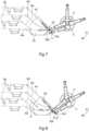
- the winding heads 10 are movable within a working path P, which is preferably closed, as schematised in Figure 3 .
- the movement device 3 comprises a rotatable body 30 which may rotate around a rotation axis C thereof.
- the rotatable body 30 supports a plurality of extendable arms 31, which are preferably hinged at one end thereof to the rotatable body 30 and, at an opposite end thereof, a respective winding head 10 is in turn supported.
- the combination of the rotatable body 30 and the extendable arms 31 allows the winding heads to make the necessary movements to follow the working path P.
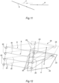
- Figure 10 illustrates a variant embodiment of the present invention wherein the winding heads 10 are directly attached to the rotatable body 30, hence without the use of extendable arms.
- the rotatable body 30 is also advantageously movable not only around its rotation axis C, but also in a direction of displacement d along which said rotatable body 30 and, in general, the movement device 3, may be displaced.
- each winding head 10 supports a grabbing device 11 which is configured to grab a portion of said strip-shaped article N.
- the winding of the strip-shaped article N can thus be obtained by rotation of the grabbing devices 11 themselves around a winding axis X thereof.
- each grabbing device 11 preferably comprises a pair of pins 12, 13 between which the strip-shaped article N is held.
- At least one of the two pins is movable in such a way as to join to the other pin holding said strip-shaped article N between them.
- At least one of the two pins is movable along an extraction direction e.
- a first pin 12 of the pair can thereby move closer the strip-shaped article N during the movement of the relative head 10 along the path P.
- the second pin 13, which is movable is intended to be arranged in a downstream position along the path P in relation to the fixed pin 12.
- the strip-shaped article may thereby be comprised between the two pins 12, 13.
- the second pin 13 may thereby be placed in a position that does not interfere with the first pin 12 moving closer to the strip-shaped article N, and it is possible to displace the second pin 13 to a position such as to hold the article N once the first pin 12 is in place.
- Figures 3 to 8 illustrate the movement of the winding heads 10 and, in general, the operation of the present invention in a preferred embodiment.
- a first winding head 10A and a second winding head 10B are therefore identified, the latter being arranged upstream along the working path P in relation to the first head 10A.
- the second winding head 10B is arranged along a reset section P2 of the working path P.
- a reset section P2 allows the working path P to be closed, and is in particular the segment along which the winding heads return to the beginning of the operative segment P1 after winding the strip-shaped article, forming the coil and unloading the latter in an unloading area 7, the latter being schematically indicated in Figures 1 and 2 . It will be appreciated that the coil B in such unloading area 7 is unloaded from the winding unit 1 to be transported to other units intended for producing the cell.
- this first portion P11 is straight and is run in a way concordant to the feed direction f of the strip-shaped article N.
- the feed paths 8 of the strips N1, N2, N3, N4 comprise a respective storage segment 81 of a variable length extending between respective pairs of diverter rollers 24, 25, preferably idle.
- the storage segments 81 extend substantially parallel to each other and the direction of the strips N1, N2, N3, N4, is diverted by the diverter roller 25 in such a way that each of the strips flows into the coupling roller 23.
- the strip N1 is substantially parallel to the direction of displacement d of the movable portion 20 and is aligned with the storage roller 23 and, consequently, the presence of the storage roller 25 is not required.
- the distance between parallel segments 81 is such that it is possible to accommodate the grippers 26 and knives 27 illustrated above between two adjoining strips in the section between the diverter roller 25 and the coupling roller 23.
- one of the rollers of each pair of diverter rollers 24, 25 is supported on the movable portion 20, in such a way that it moves integrally with it, as will be illustrated in greater detail hereinafter.
- the length of the storage segments 81 of each strip may be simultaneously varied by moving the movable portion 20.
- the storage segments 81 extend substantially parallel to each other, remaining substantially parallel even during and after the displacement of the movable portion 20 and, consequently, of their length variation.
- the displacement direction d may preferably be substantially parallel to the feed direction f.
- the same result may be achieved by suitably arranging the rollers 24, 25 between which the storage segments 81 extend.
- the movement of the movable portion 20 is, in this case as well, associated with a change in the length of each of the storage segments 81.
- the movement of the winding head along the portion P11 may be accompanied by a corresponding movement of the movable portion 20 along the displacement direction d.
- winding heads 10 and the movable portion 20 may be moved in a coordinated way. In other words, the movement of the winding heads 10 and the movable portion 20 occurs synchronously.
- the distance between the winding head 10, which is winding or more generally holding the strip, and the movable portion 20 of the winding unit 2 may thereby be controlled. Consequently, it will be advantageously possible to provide that the length of strip-shaped article N between the winding unit 2 and the winding head that is holding it is minimum or at least equal to a predetermined distance.
- the displacement direction d may be substantially parallel to the first portion P11 of the operative segment P1.
- the term “substantially parallel” will still refer to a possible deviation of ⁇ 10° and preferably ⁇ 5° from a perfect parallelism.
- the winding head 10 can also start winding the strip-shaped article N.
- this is in particular related to the ratio between the feed speed v f with which the strip-shaped article is fed by the feed unit 2 and the displacement speed v sp with which the winding heads move along the portion P11.
- the strip-shaped article N can be wound at such a winding speed as to compensate for the difference between the two aforesaid speeds.
- the strip-shaped article N which is fed is either wound or stored as illustrated above.
- the strip-shaped article N may be kept at a substantially constant tension by suitably acting on the movement speeds of the head while it is winding and/or holding the strip-shaped article N.
- the feed speed v f is preferably determined by the speed at which the delivery coils forming the delivery device 6 are rotated to unwind the strip, pushing, and then feeding, the strip into the feed unit 1 and then into the winding unit 3. More generally, such speed may be determined by the actuating mode of the delivery device 6.
- winding the strip-shaped article N via the winding heads 10 can also help determine the feed speed v f , with a pull action on each strip.
- the coils, or other delivery device 6, are not motor-driven, and are therefore idle, the strip could be advanced solely by the winding action.
- the movement of the head 10A may advantageously be associated with a corresponding displacement of the movable portion 20 of the feed unit 2.
- the strip-shaped article N is wound by the head itself, preferably at a higher winding speed than that provided for the portion P11.
- the amounts of strips stored in the previous step may therefore be wound while the winding head 10A moves along the portion P12.
- the feed speed v f , the winding speed v avv and the displacement speed v sp will preferably be such that the strip-shaped article N is subjected to a substantially constant tension.
- this may be achieved by providing the feed speed v f to be substantially equal to the sum of said winding speed v avv and said displacement speed v sp .
- the rotatable body 30 of the movement device 3 proceeds with its continuous rotation motion, while the arm 31 is rotated in the opposite direction, thus performing a movement opposite to that performed during the movement along the portion P11.
- the arm 31 swings back and forth in such a way that the winding head may perform the previously described movement and the winding of the strip-shaped article.
- the first winding head 6 may be moved away from the outlet section 22.
- Such movement may take place by moving the head itself and/or displacing the movable portion 20.
- a sufficient space may be provided such that a second winding head 10B, arranged upstream from the first winding head 10A along the path P, may be interposed between the first winding head 10A and the outlet section 22.
- the distance between the first winding head 10A and the second winding head 10B is variable along the working path P, depending on the operating steps of the apparatus 100.
- the strip-shaped article N is simultaneously grabbed on both the first winding head 10A and the second winding head 10B.
- a cutting device 5 may be provided which is configured in such a way as to cut said strip-shaped article N at a position downstream of said feed unit 2 and, advantageously, at the aforesaid position.
- the cutting device 5 advantageously cuts the strip-shaped article N, when the respective winding head 10 is positioned at said predetermined distance from said feed unit 2, advantageously substantially equal to the minimum distance compatible with the kinematic mechanisms determining the movement of the winding heads 10.
- the cutting device 5 is illustrated in a preferred embodiment thereof in Figure 9 .
- the winding head 10 comprises an abutment element 14 placed in such a position that the strip-shaped article N is interposed between the abutment element 14 and the cutting device 5.
- the cut carried out by the device 5 can only affect the separator strips N2, N4 that form the strip-shaped article N following the interruption of the conductor strips.
- the cutting device 5 is also movable in a direction substantially parallel to the feed direction f.
- the cutting device is movable with at least one component substantially parallel to that direction.
- the cutting device 5 may be supported on the movable portion 20 or movable integrally thereto. It will be thereby possible to both move the cutting device 5 closer to the abutment element 14 and move it synchronously to the strip-shaped article N. In other words, the cutting device 5 copies the movement of the strip-shaped article N, moving synchronously thereto when it performs the cutting operation.
- the strip-shaped article N is fed with a feed speed v f that is constantly greater than zero, and preferably substantially constant, as it is possible that the cut is performed while the strip-shaped article is also moving.
- the strips forming the strip-shaped article N may also be continuously advanced within the feed unit 2.
- the continuous advancement will preferably be associated with the possibility of storing the strip.
- this/these may be advanced continuously through the outlet section 22, in continuity with the strip-shaped article N.
- the process of making the coil B provides a third portion P13 of the operative segment P1, preferably substantially parallel to said first and second portions P11, P12 and along which the winding head 10A moves after cutting the strip-shaped article N.
- the winding head moves again in a direction concordant with said feed direction f along said third portion P13.
- said movement device 3 is configured in such a way that when the first winding head 10A runs along said third portion P13, the second winding head 10, which has advantageously just grabbed the strip-shaped article N, runs along the first portion P11 performing, in sequence, the steps described above in relation to the first winding head 10A.
- the first winding head completes the winding of the flap of strip-shaped article N resulting from the cut, finishing the manufacturing of the coil B.
- the winding of the strip-shaped article N to make the coil B can take place in each of the three portions P11, P12, P13.
- winding mainly takes place, i.e. by a greater percentage amount, along the second portion P12.
- the strip is wound for an amount of between 5% and 15%, preferably 10%, of the total length of the strip-shaped article forming a single coil along the first portion P11, for an amount of between 70% and 90%, preferably 80%, along the second portion P12 and for an amount of between 5% and 15%, preferably 10%, along the third portion P13.
- the displacement of the first winding head 10A then continues until it reaches the unloading area 7, where the coil B is unloaded from the winding unit 1.
- the additional working unit 60 may comprise a bending device configured to bend the two opposite axial ends of the coil.
- the conductor strips each protrude axially, one on one side and the other on the other side, and are bent in such a way as to form a single portion of a conductor intended to be connected to an anode/cathode end in the cell once assembled.
- a coil closing element B configured in such a way as to prevent the coil from unwinding once unloaded from the winding head 10, may also be provided.
- a closing element may, for example, be represented by a strip applied circumferentially to the coil to close the end flap of the strip-shaped element.
- the steps described above may then be repeated cyclically for each of the winding heads 10 included in winding unit 1.
- Figure 10 illustrates a possible illustrative variant of the apparatus according to the present invention.
- the movement device 3 moves integrally with the movable portion 20 of the winding unit 2.
- the movement device 3 may be rotatably supported around the rotation axis C on the movable portion 20.
- the movement device 3 may move as a whole, as in the example illustrated wherein it moves along the displacement direction d, it may therefore be provided that the winding heads 10 remain in a substantially fixed position in relation to the rotating body 3 and that, consequently, their distance from each other remains unchanged.
- the movement heads 10 may in this case move not only by rotating on themselves for winding the strip-shaped article N, but also as a result of the movement of the rotating body of the movement device 3, preferably of its linear movement.
- such movement includes both the rotation around the axis C and the translation along the displacement direction d.
- the movement of the movement heads 10 may in this case be determined by any rotation and any translation or further rotation, always in addition to the rotation carried out to wind the strip-shaped article N.
Landscapes
- Engineering & Computer Science (AREA)
- Mechanical Engineering (AREA)
- Manufacturing & Machinery (AREA)
- Chemical & Material Sciences (AREA)
- Chemical Kinetics & Catalysis (AREA)
- Electrochemistry (AREA)
- General Chemical & Material Sciences (AREA)
- Primary Cells (AREA)
- Fixed Capacitors And Capacitor Manufacturing Machines (AREA)
- Secondary Cells (AREA)
- Winding Of Webs (AREA)
Applications Claiming Priority (7)
| Application Number | Priority Date | Filing Date | Title |
|---|---|---|---|
| IT102021000032015A IT202100032015A1 (it) | 2021-12-21 | 2021-12-21 | Macchina confezionatrice e metodo di confezionamento di una cella elettrochimica cilindrica |
| IT102021000032009A IT202100032009A1 (it) | 2021-12-21 | 2021-12-21 | Macchina confezionatrice e metodo di confezionamento di una cella elettrochimica cilindrica |
| IT102021000032012A IT202100032012A1 (it) | 2021-12-21 | 2021-12-21 | Macchina confezionatrice e metodo di confezionamento di una cella elettrochimica cilindrica |
| IT102022000008102A IT202200008102A1 (it) | 2022-04-22 | 2022-04-22 | Apparato e metodo per la realizzazione di una bobina, preferibilmente per una cella elettrochimica destinata alla produzione di batterie |
| IT102022000008033A IT202200008033A1 (it) | 2022-04-22 | 2022-04-22 | Apparato e metodo per la realizzazione di una bobina, preferibilmente per una cella elettrochimica destinata alla produzione di batterie |
| EP22846940.9A EP4452804A1 (de) | 2021-12-21 | 2022-12-21 | Vorrichtung und verfahren zur herstellung einer spule, vorzugsweise für eine elektrochemische zelle zur herstellung von batterien |
| PCT/IB2022/062611 WO2023119184A1 (en) | 2021-12-21 | 2022-12-21 | Apparatus and method for making a coil, preferably for an electrochemical cell intended for producing batteries |
Related Parent Applications (1)
| Application Number | Title | Priority Date | Filing Date |
|---|---|---|---|
| EP22846940.9A Division EP4452804A1 (de) | 2021-12-21 | 2022-12-21 | Vorrichtung und verfahren zur herstellung einer spule, vorzugsweise für eine elektrochemische zelle zur herstellung von batterien |
Publications (2)
| Publication Number | Publication Date |
|---|---|
| EP4535477A2 true EP4535477A2 (de) | 2025-04-09 |
| EP4535477A3 EP4535477A3 (de) | 2025-07-09 |
Family
ID=85017987
Family Applications (2)
| Application Number | Title | Priority Date | Filing Date |
|---|---|---|---|
| EP24223214.8A Pending EP4535477A3 (de) | 2021-12-21 | 2022-12-21 | Vorrichtung und verfahren zur herstellung einer spule, vorzugsweise für eine elektrochemische zelle zur herstellung von batterien |
| EP22846940.9A Pending EP4452804A1 (de) | 2021-12-21 | 2022-12-21 | Vorrichtung und verfahren zur herstellung einer spule, vorzugsweise für eine elektrochemische zelle zur herstellung von batterien |
Family Applications After (1)
| Application Number | Title | Priority Date | Filing Date |
|---|---|---|---|
| EP22846940.9A Pending EP4452804A1 (de) | 2021-12-21 | 2022-12-21 | Vorrichtung und verfahren zur herstellung einer spule, vorzugsweise für eine elektrochemische zelle zur herstellung von batterien |
Country Status (6)
| Country | Link |
|---|---|
| US (1) | US20250100037A1 (de) |
| EP (2) | EP4535477A3 (de) |
| JP (1) | JP2025503479A (de) |
| KR (1) | KR20240128936A (de) |
| CA (1) | CA3241597A1 (de) |
| WO (1) | WO2023119184A1 (de) |
Families Citing this family (1)
| Publication number | Priority date | Publication date | Assignee | Title |
|---|---|---|---|---|
| IT202200008033A1 (it) * | 2022-04-22 | 2023-10-22 | Gd Spa | Apparato e metodo per la realizzazione di una bobina, preferibilmente per una cella elettrochimica destinata alla produzione di batterie |
Citations (1)
| Publication number | Priority date | Publication date | Assignee | Title |
|---|---|---|---|---|
| WO2010023525A1 (en) | 2008-08-28 | 2010-03-04 | Toyota Jidosha Kabushiki Kaisha | Method and apparatus for producing wound electrode assembly, and method for producing battery |
Family Cites Families (8)
| Publication number | Priority date | Publication date | Assignee | Title |
|---|---|---|---|---|
| JP2003017111A (ja) * | 2001-07-04 | 2003-01-17 | Toray Eng Co Ltd | 二次電池および二次電池製造方法ならびに二次電池製造装置 |
| ITBO20040120A1 (it) * | 2004-02-27 | 2004-05-27 | Arcotronics Italia Spa | Procedimento per la realizzazione di componenti elettrici, di tipo elettrostatico o elettrochimico, ad accumulo di energia, macchina che attua tale procedimento e componenti secondo il procedimento |
| JP6034630B2 (ja) * | 2012-09-14 | 2016-11-30 | 株式会社皆藤製作所 | 蓄電素子、巻回方法、及び巻回装置 |
| JP5809177B2 (ja) * | 2013-02-13 | 2015-11-10 | Ckd株式会社 | 捲回装置 |
| JP6062880B2 (ja) * | 2014-03-24 | 2017-01-18 | Ckd株式会社 | 捲回装置 |
| JP6670769B2 (ja) * | 2017-01-13 | 2020-03-25 | Ckd株式会社 | 検査装置及び巻回装置 |
| ES2951034T3 (es) * | 2018-05-18 | 2023-10-17 | Siemens Ag | Procedimiento para bobinar un producto a bobinar |
| CN113241480B (zh) * | 2021-05-11 | 2022-11-11 | 深圳吉阳智能科技有限公司 | 隔膜不停匀速高效卷绕机 |
-
2022
- 2022-12-21 KR KR1020247024740A patent/KR20240128936A/ko active Pending
- 2022-12-21 JP JP2024537836A patent/JP2025503479A/ja active Pending
- 2022-12-21 CA CA3241597A patent/CA3241597A1/en active Pending
- 2022-12-21 EP EP24223214.8A patent/EP4535477A3/de active Pending
- 2022-12-21 EP EP22846940.9A patent/EP4452804A1/de active Pending
- 2022-12-21 WO PCT/IB2022/062611 patent/WO2023119184A1/en not_active Ceased
- 2022-12-21 US US18/722,548 patent/US20250100037A1/en active Pending
Patent Citations (1)
| Publication number | Priority date | Publication date | Assignee | Title |
|---|---|---|---|---|
| WO2010023525A1 (en) | 2008-08-28 | 2010-03-04 | Toyota Jidosha Kabushiki Kaisha | Method and apparatus for producing wound electrode assembly, and method for producing battery |
Also Published As
| Publication number | Publication date |
|---|---|
| WO2023119184A1 (en) | 2023-06-29 |
| JP2025503479A (ja) | 2025-02-04 |
| EP4535477A3 (de) | 2025-07-09 |
| US20250100037A1 (en) | 2025-03-27 |
| KR20240128936A (ko) | 2024-08-27 |
| EP4452804A1 (de) | 2024-10-30 |
| CA3241597A1 (en) | 2023-06-29 |
Similar Documents
| Publication | Publication Date | Title |
|---|---|---|
| US20250266487A1 (en) | Apparatus and method for making a coil, preferably for an electrochemical cell intended for the production of batteries | |
| US20250158102A1 (en) | Apparatus and Method for Making a Coil, Preferably for an Electrochemical Cell Intended for the Production of Batteries | |
| EP4535475A2 (de) | Vorrichtung und verfahren zur herstellung einer spule, vorzugsweise für eine elektrochemische zelle zur herstellung von batterien | |
| KR20250047295A (ko) | 바람직하게는 배터리 생산을 위한 전기화학 셀을 위한, 코일을 만들기 위한 장치 및 방법 | |
| EP4535478A2 (de) | Vorrichtung und verfahren zur herstellung einer spule, vorzugsweise für eine elektrochemische zelle zur herstellung von batterien | |
| EP4535474A2 (de) | Vorrichtung und verfahren zur herstellung einer spule, vorzugsweise für eine elektrochemische zelle zur herstellung von batterien | |
| US20250042682A1 (en) | Apparatus and Method for Making a Coil, Preferably for an Electrochemical Cell Intended for the Production of Batteries | |
| US20250100037A1 (en) | Apparatus and Method for Making a Coil, Preferably for an Electrochemical Cell Intended for the Production of Batteries | |
| EP4535476A2 (de) | Vorrichtung und verfahren zur herstellung einer spule, vorzugsweise für eine elektrochemische zelle zur herstellung von batterien | |
| US20250135521A1 (en) | Apparatus and Method for Making a Coil, Preferably for an Electrochemical Cell Intended for the Production of Batteries | |
| CN118414293A (zh) | 用于对优选用于生产电池用的电化学电芯的线圈进行制造的设备和方法 | |
| CA3220967A1 (en) | Automatic machine for the production of electrical energy storage devices starting from at least one strip of material and motion transmission assembly |
Legal Events
| Date | Code | Title | Description |
|---|---|---|---|
| PUAI | Public reference made under article 153(3) epc to a published international application that has entered the european phase |
Free format text: ORIGINAL CODE: 0009012 |
|
| STAA | Information on the status of an ep patent application or granted ep patent |
Free format text: STATUS: THE APPLICATION HAS BEEN PUBLISHED |
|
| AC | Divisional application: reference to earlier application |
Ref document number: 4452804 Country of ref document: EP Kind code of ref document: P |
|
| AK | Designated contracting states |
Kind code of ref document: A2 Designated state(s): AL AT BE BG CH CY CZ DE DK EE ES FI FR GB GR HR HU IE IS IT LI LT LU LV MC ME MK MT NL NO PL PT RO RS SE SI SK SM TR |
|
| REG | Reference to a national code |
Ref country code: DE Ref legal event code: R079 Free format text: PREVIOUS MAIN CLASS: H01M0010040000 Ipc: B65H0023188000 |
|
| PUAL | Search report despatched |
Free format text: ORIGINAL CODE: 0009013 |
|
| AK | Designated contracting states |
Kind code of ref document: A3 Designated state(s): AL AT BE BG CH CY CZ DE DK EE ES FI FR GB GR HR HU IE IS IT LI LT LU LV MC ME MK MT NL NO PL PT RO RS SE SI SK SM TR |
|
| RIC1 | Information provided on ipc code assigned before grant |
Ipc: H01M 10/0587 20100101ALI20250603BHEP Ipc: H01M 10/04 20060101ALI20250603BHEP Ipc: B65H 20/34 20060101ALI20250603BHEP Ipc: B65H 23/188 20060101AFI20250603BHEP |
|
| STAA | Information on the status of an ep patent application or granted ep patent |
Free format text: STATUS: REQUEST FOR EXAMINATION WAS MADE |
|
| 17P | Request for examination filed |
Effective date: 20260108 |