EP4535523A1 - Batterie, son procédé de fabrication, module de batterie et dispositif électrique - Google Patents
Batterie, son procédé de fabrication, module de batterie et dispositif électrique Download PDFInfo
- Publication number
- EP4535523A1 EP4535523A1 EP23829538.0A EP23829538A EP4535523A1 EP 4535523 A1 EP4535523 A1 EP 4535523A1 EP 23829538 A EP23829538 A EP 23829538A EP 4535523 A1 EP4535523 A1 EP 4535523A1
- Authority
- EP
- European Patent Office
- Prior art keywords
- side wall
- housing
- groove
- annular
- groove side
- Prior art date
- Legal status (The legal status is an assumption and is not a legal conclusion. Google has not performed a legal analysis and makes no representation as to the accuracy of the status listed.)
- Pending
Links
Images





Classifications
-
- H—ELECTRICITY
- H01—ELECTRIC ELEMENTS
- H01M—PROCESSES OR MEANS, e.g. BATTERIES, FOR THE DIRECT CONVERSION OF CHEMICAL ENERGY INTO ELECTRICAL ENERGY
- H01M50/00—Constructional details or processes of manufacture of the non-active parts of electrochemical cells other than fuel cells, e.g. hybrid cells
- H01M50/10—Primary casings; Jackets or wrappings
- H01M50/102—Primary casings; Jackets or wrappings characterised by their shape or physical structure
- H01M50/107—Primary casings; Jackets or wrappings characterised by their shape or physical structure having curved cross-section, e.g. round or elliptic
-
- H—ELECTRICITY
- H01—ELECTRIC ELEMENTS
- H01M—PROCESSES OR MEANS, e.g. BATTERIES, FOR THE DIRECT CONVERSION OF CHEMICAL ENERGY INTO ELECTRICAL ENERGY
- H01M10/00—Secondary cells; Manufacture thereof
- H01M10/05—Accumulators with non-aqueous electrolyte
- H01M10/052—Li-accumulators
- H01M10/0525—Rocking-chair batteries, i.e. batteries with lithium insertion or intercalation in both electrodes; Lithium-ion batteries
-
- H—ELECTRICITY
- H01—ELECTRIC ELEMENTS
- H01M—PROCESSES OR MEANS, e.g. BATTERIES, FOR THE DIRECT CONVERSION OF CHEMICAL ENERGY INTO ELECTRICAL ENERGY
- H01M10/00—Secondary cells; Manufacture thereof
- H01M10/05—Accumulators with non-aqueous electrolyte
- H01M10/058—Construction or manufacture
-
- H—ELECTRICITY
- H01—ELECTRIC ELEMENTS
- H01M—PROCESSES OR MEANS, e.g. BATTERIES, FOR THE DIRECT CONVERSION OF CHEMICAL ENERGY INTO ELECTRICAL ENERGY
- H01M50/00—Constructional details or processes of manufacture of the non-active parts of electrochemical cells other than fuel cells, e.g. hybrid cells
- H01M50/10—Primary casings; Jackets or wrappings
- H01M50/147—Lids or covers
- H01M50/166—Lids or covers characterised by the methods of assembling casings with lids
- H01M50/167—Lids or covers characterised by the methods of assembling casings with lids by crimping
-
- Y—GENERAL TAGGING OF NEW TECHNOLOGICAL DEVELOPMENTS; GENERAL TAGGING OF CROSS-SECTIONAL TECHNOLOGIES SPANNING OVER SEVERAL SECTIONS OF THE IPC; TECHNICAL SUBJECTS COVERED BY FORMER USPC CROSS-REFERENCE ART COLLECTIONS [XRACs] AND DIGESTS
- Y02—TECHNOLOGIES OR APPLICATIONS FOR MITIGATION OR ADAPTATION AGAINST CLIMATE CHANGE
- Y02E—REDUCTION OF GREENHOUSE GAS [GHG] EMISSIONS, RELATED TO ENERGY GENERATION, TRANSMISSION OR DISTRIBUTION
- Y02E60/00—Enabling technologies; Technologies with a potential or indirect contribution to GHG emissions mitigation
- Y02E60/10—Energy storage using batteries
Definitions
- This application relates to the field of batteries and specifically, to a battery and a manufacturing method thereof, a battery module, and an electric device.
- the applicant has designed a battery.
- An annular groove of a housing of the battery is crimped and the crimping degree of the annular groove is controlled to meet a specified criterion, thereby alleviating the problem that cylindrical batteries are prone to electrolyte leakage.
- h2 is less than h1 and ⁇ 1 is less than 90°, indicating that the annular groove is so crimped that it tilts downward with a reduced height at the opening.
- 0.2h1 ⁇ h2 ⁇ 0.8h1 and 10° ⁇ ⁇ 1 ⁇ 80° are set to make the crimping degree of the annular groove meet a specified criterion. This can alleviate the problem that cylindrical batteries are prone to electrolyte leakage.
- 0.2h1 ⁇ h2 0.5h1 and 10° ⁇ ⁇ 1 ⁇ 60°.
- setting 0.2h1 ⁇ h2 ⁇ 0.5h1 and 10° ⁇ ⁇ 1 ⁇ 60° makes the annular groove have a more suitable crimping degree. This can better alleviate the problem that batteries are prone to electrolyte leakage.
- an end of the annular bent edge close to the housing side wall is a first bent-edge end and an end of the annular bent edge away from the housing side wall is a second bent-edge end; and a connection line direction from the first bent-edge end to the second bent-edge end is a bent edge direction, and an included angle between the bent edge direction and the housing side wall adjacent is ⁇ 2, where 1° ⁇ (90° - ⁇ 2) ⁇ 25°.
- setting 85° ⁇ ⁇ 3 ⁇ 95° makes the second groove side wall and the housing side wall adjacent basically perpendicular to each other.
- the annular groove is so crimped that it tilts downward with a reduced height at the opening, it indicates that when the annular groove is crimped, the second groove side wall basically neither tilts nor deforms.
- the annular groove mainly performs sealing through pressing between the second groove side wall and a partial sealing ring corresponding to the second groove side wall, this configuration guarantees that crimping induced deformation can desirably improve the airtightness between the second groove side wall and the partial sealing ring corresponding to the second groove side wall.
- a part of the housing side wall located between the annular groove and the annular bent edge is a cap part; in the height direction of the housing body, height of the cap part is h3; and in a radial direction of the housing body, width of the annular bent edge is L1; where 0.8L1 ⁇ h3 ⁇ 1.5L1.
- L1 is too small and therefore it is not easy to perform downward bending on the housing body so as to form the annular bent edge, making processing difficult and likely causing insufficient airtightness between the annular bent edge and a partial sealing ring corresponding to the annular bent edge.
- this application provides an electric device including the battery in the foregoing embodiments.
- mount In the description of some embodiments of this application, unless otherwise specified and defined explicitly, the technical terms “mount”, “connect”, “join”, “fix” and the like should be understood in their general senses. For example, they may refer to a fixed connection, a detachable connection, or an integral connection and may refer to a direct connection or an indirect connection via an intermediate medium. Persons of ordinary skill in the art can understand specific meanings of these terms in the embodiments of this application as appropriate to specific situations.
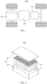
- FIG. 2 is an exploded view of a battery module 100 according to some embodiments of this application.
- the battery module 100 may include a box 10 and a battery 20, and the battery 20 is accommodated in the box 10.
- the box 10 is configured to accommodate the battery 20, and the box 10 may have various structures.
- the box 10 may include a first portion 11 and a second portion 12.
- the first portion 11 and the second portion 12 fit together to jointly define an accommodating space 13 for accommodating the battery 20.
- the second portion 12 may be a hollow structure with one end open, the first portion 11 is a plate-shaped structure, and the first portion 11 covers the opening side of the second portion 12 so as to form the box 10 having the accommodating space 13.
- one or multiple batteries 20 may be provided. If multiple batteries 20 are provided, the multiple batteries 20 may be connected in series, parallel, or series-parallel, where being connected in series-parallel means a combination of series and parallel connections of the multiple batteries 20.
- the multiple batteries 20 may be directly connected in series, parallel, or series-parallel, and then an entirety of the multiple batteries 20 is accommodated in the box 10.
- the multiple batteries 20 may alternatively be connected first in series, parallel, or series-parallel first to form a module, and then multiple modules are connected in series, parallel, or series-parallel to form an entirety which is accommodated in the box 10.
- the battery module 100 may further include other structures.
- the multiple batteries 20 may be electrically connected via a busbar so that the multiple batteries 20 are connected in series, parallel, or series-parallel.
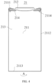
- the housing 21 may include a housing body 211 and a cover 212.
- the housing body 211 is a component configured to form an internal sealed space 213 of the battery 20 together with the cover 212.
- the internal sealed space 213 formed can be configured to accommodate the electrode assembly 22, the electrolyte, and other components.
- the cover 212 is a component that fits over an opening of the housing body 211 to separate an internal environment of the battery 20 from an external environment.
- the shape of the cover 212 may be adapted to the shape of the housing body 211 to fit the housing body 211.
- the cover 212 may be further provided with functional components such as an electrode terminal and a pressure relief structure.
- a sealing ring 214 is configured between the opening of the housing body 211 and the cover 212 to implement airtightness between the housing body 211 and the cover 212.
- the first groove side wall 21141 is located on a side of the annular groove 2114 closer to the housing bottom wall 2113, and the second groove side wall 21143 is located on a side of the annular groove 2114 farther away from the housing bottom wall 2113.
- a plating layer may be formed on an outer side of the housing body 211.
- the housing body 211 may be an integral structure, in other words, the annular bent edge 2111, the housing side wall 2112, and the housing bottom wall 2113 are formed integrally.
- the housing body 211 being cylindrical means that the battery 20 is a cylindrical battery 20, with the housing side wall 2112 being cylindrical as a whole; the housing bottom wall 2113 having a circular cross-section perpendicular to the height direction B of the housing body, and the housing bottom wall 2113 being located at the bottom of the housing side wall 2112 and completely closing the bottom of the housing side wall 2112.
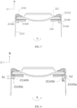
- height of the groove bottom wall 21142 is h1 and height of the opening 21144 of the annular groove is h2.
- An end of the first groove side wall 21141 close to the housing side wall 2112 is a first end of groove side wall 21141a, and an end of the first groove side wall 21141 away from the housing side wall 2112 is a second end of groove side wall 21141b; and a connection line direction from the first end of groove side wall 21141a to the second end of groove side wall 21141b is an extension direction of the first groove side wall 21141, and an included angle between the extension direction of the first groove side wall 21141 and the housing side wall 2112 adjacent is ⁇ 1; where 0.2h1 ⁇ h2 ⁇ 0.8h1 and 10° ⁇ ⁇ 1 ⁇ 80°.
- the first end of groove side wall 21141a is connected to the housing side wall 2112, and the second end of groove side wall 21141b is connected to the groove bottom wall 21142.
- An end of the groove bottom wall 21142 connected to the first groove side wall 21141 is a first end of groove bottom wall 21142a
- an end of the groove bottom wall 21142 connected to the second groove side wall 21143 is a second end of groove bottom wall 21142b.
- a joint of the groove bottom wall 21142 and the first groove side wall 21141 has a corner and the corner (for example, the middle point of the corner) can represent the joint of the two, namely, ends of the two.
- ends of the components may also be determined according to the above criterion. Details are not repeated.
- the height of the groove bottom wall is a distance from a lowest point to a highest point of the annular groove on the longitudinal cross-section of the housing body through the axis in the height direction of the housing body.
- the height of the groove bottom wall 21142 is a distance between the first end of groove bottom wall 21142a (that is, the lowest point of the annular groove) and the second end of groove bottom wall 21142b (the highest point of the annular groove) on the longitudinal cross-section of the housing body 211 through the axis in the height direction B of the housing body.
- connection line direction from the first end of groove side wall 21141a to the second end of groove side wall 21141b is an extension direction corresponding to a connection line between the first end of groove side wall 21141a and the second end of groove side wall 21141b on the longitudinal cross-section of the housing body 211 through the axis.
- the housing side wall 2112 adjacent in the description of the extension direction of the first groove side wall 21141 and the housing side wall 2112 adjacent is a part of the housing side wall 2112 directly connecting to the first groove side wall 21141.
- ⁇ 1 is an included angle between the extension direction of the first groove side wall 21141 and the housing side wall 2112 adjacent on the longitudinal cross-section of the housing body 211 through the axis.
- the height of the groove bottom wall 21142 and the height of the opening 21144 of the annular groove are the same.
- the first groove side wall 21141 and the second groove side wall 21143 extend along the radial direction C of the housing body and are perpendicular to the housing side wall 2112.
- 0.2h1 ⁇ h2 ⁇ 0.8h1 indicates that the annular groove 2114 has a reduced height at the opening
- 10° ⁇ ⁇ 1 ⁇ 80° indicates that the first groove side wall 21141 tilts downward.
- the annular groove 2114 in the housing body 211 of this embodiment of this application is so crimped that it tilts downward with a reduced height at the opening.
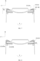
- connection line direction from the first bent-edge end 2111a to the second bent-edge end 2111b is an extension direction corresponding to a connection line between the first bent-edge end 2111a and the second bent-edge end 2111b on the longitudinal cross-section of the housing body 211 through the axis.
- the housing side wall 2112 adjacent in the description of the bent edge direction and the housing side wall 2112 adjacent is a part of the housing side wall 2112 directly connecting to the annular bent edge 2111.
- ⁇ 2 is an included angle between the bent edge direction and the housing side wall 2112 adjacent on the longitudinal cross-section of the housing body 211 through the axis.
- ⁇ 2 indicates the value of the included angle between the annular bent edge 2111 and the housing side wall 2112 adjacent
- (90° - ⁇ 2) indicates an angle by which the annular bent edge 2111 is bent away from a position where the annular bent edge 2111 is perpendicular to the housing side wall 2112 adjacent.
- (90° - ⁇ 2) indicates a downward bending degree of the annular bent edge 2111.
- the material of each part in the battery 20, the size of each part, the size ratio between different parts, the angle between different parts, and the like may be selected with reference to conventional models of batteries 20, for example, 18650 or 21700.
- the dimensions of other components may also be correspondingly set according to the design requirements of conventional models.
- an end of the second groove side wall 21143 close to the housing side wall 2112 is a third end of groove side wall 21143a and an end of the second groove side wall 21143 away from the housing side wall 2112 is a fourth end of groove side wall 21143b; and a connection line direction from the fourth end of groove side wall 21143b to the third end of groove side wall 21143a is an extension direction of the second groove side wall 21143, and an included angle between the extension direction of the second groove side wall 21143 and the housing side wall 2112 adjacent is ⁇ 3, where 85° ⁇ ⁇ 3 ⁇ 95°.
- the third end of groove side wall 21143a is connected to the housing side wall 2112, and the fourth end of groove side wall is connected to the groove bottom wall 21142.
- the connection line direction from the fourth end of groove side wall 21143b to the third end of groove side wall 21143a is an extension direction corresponding to a connection line between the third end of groove side wall 21143a and the fourth end of groove side wall 21143b on the longitudinal cross-section of the housing body 211 through the axis.
- the housing side wall 2112 adjacent in the description of the extension direction of the second groove side wall 21143 and the housing side wall 2112 adjacent is a part of the housing side wall 2112 directly connecting to the second groove side wall 21143 and may be the cap part 21121.
- ⁇ 3 is an included angle between the extension direction of the second groove side wall 21143 and the housing side wall 2112 adjacent on the longitudinal cross-section of the housing body 211 through the axis.
- ⁇ 3 is 90°, and this indicates that the second groove side wall 21143 and the housing side wall 2112 adjacent are perpendicular.
- setting 85° ⁇ ⁇ 3 ⁇ 95° makes the second groove side wall 21143 and the housing side wall 2112 adjacent basically perpendicular to each other.
- the annular groove 2114 is so crimped that it tilts downward with a reduced height at the opening, it indicates that when the annular groove 2114 is crimped, the second groove side wall 21143 basically neither tilts nor deforms.
- D of batteries 20 of particular dimensions is generally fixed.
- the ratio of L1 to D is too large, the width of the annular bent edge 2111 is too large and therefore it is not easy to control the downward bending angle of the annular bent edge 2111, making processing difficult.
- the ratio of L1 to D is too small, the width of the annular bent edge 2111 is too small and therefore it is not easy to perform downward bending on the housing body 211 so as to form the annular bent edge 2111, making processing difficult and likely causing insufficient airtightness between the annular bent edge 2111 and a partial sealing ring 214 corresponding to the annular bent edge 2111.
- a part of the housing side wall 2112 located between the annular groove 2114 and the annular bent edge 2111 is a cap part 21121; in the height direction B of the housing body, height of the cap part 21121 is h3; and in a radial direction of the housing body, width of the annular bent edge 2111 is L1; where 0.8L1 ⁇ h3 ⁇ 1.5L1.
- the ratio of h3 to L1 is, for example, but not limited to any one of 0.8, 0.9, 1, 1.1, 1.2, 1.3, 1.4, and 1.5 or in a range defined by any two of these values.
- the cap part 21121 and the annular bent edge 2111 are sealing parts of the housing body 211 located on a side of the annular groove 2114 farther away from the housing bottom wall 2113.
- a sum of the dimensions of the sealing parts meets a specified criterion. If the ratio of h3 to L1 is too small, it indicates that h3 is too small. In this case, L1 is too large and therefore it is not easy to control the downward bending angle of the annular bent edge 2111, making processing difficult. If the ratio of h3 to L1 is too large, it indicates that h3 is too large.
- L1 is too small and therefore it is not easy to perform downward bending on the housing body 211 so as to form the annular bent edge 2111, making processing difficult and likely causing insufficient airtightness between the annular bent edge 2111 and a partial sealing ring 214 corresponding to the annular bent edge 2111.
- setting 0.8L1 ⁇ h3 ⁇ 1.5L1 makes the width of the annular bent edge 2111 controlled within a proper range, facilitating downward bending of the housing body 211 to form the annular bent edge 2111 in a manufacturing process.
- this application provides a battery module 100 including a box 10 and the battery 20 according to the foregoing embodiments.
- the battery 20 is accommodated in the box 10.
- this application provides a manufacturing method of battery 20 according to some embodiments of this application, as shown in FIG. 4 .
- the manufacturing method includes: providing a presealed housing body 215 of a battery 20, where the presealed housing body 215 is cylindrical; the presealed housing body 215 includes a to-be-bent housing wall 2151, a housing side wall 2112, and a housing bottom wall 2113 (not shown in the figure) that are sequentially connected; the to-be-bent housing wall 2151 is configured to bend down to form an annular bent edge 2111; the housing side wall 2112 has an annular groove 2114 distributed along a circumferential direction A1 of the presealed housing body; with reference to FIGs.
- the annular groove 2114 has a first groove side wall 21141, a groove bottom wall 21142, and a second groove side wall 21143 that are sequentially connected; the first groove side wall 21141 is located on a side of the annular groove 2114 closer to the housing bottom wall 2113, and the second groove side wall 21143 is located on a side of the annular groove 2114 farther away from the housing bottom wall 2113; in a height direction B1 of the presealed housing body, height of the groove bottom wall 21142 is h1 and height of an opening 21144 of the annular groove is h2; an end of the first groove side wall 21141 close to the housing side wall 2112 is a first end of groove side wall 21141a, and an end of the first groove side wall 21141 away from the housing side wall 2112 is a second end of groove side wall 21141b; and a connection line direction from the first end of groove side wall 21141a to the second end of groove side wall 21141b is an extension direction of the first groove side wall 21141, and an included
- the manufacturing method of battery 20 provided in this embodiment of this application can be used to manufacture the battery 20 provided in the foregoing embodiment, and process steps and parameters may be designed according to the structural requirements of the battery 20 of the foregoing embodiment.
- the presealed housing body 215 proposed in the manufacturing method corresponds to the housing body 211 in the battery 20.
- the presealed housing body 215 reference may be made to the relevant description of the housing body 211 of the battery 20 for both term explanation and design requirements for dimensions, angles, and the like of structures such as the groove bottom wall 21142 and the groove side wall except for structures such as the to-be-bent housing wall 2151 and the annular groove 2114 that deform during sealing. Details are not repeated herein.
- the to-be-bent housing wall 2151 is configured to bend down to form the annular bent edge 2111 and goes through bending during sealing.
- the to-be-bent housing wall 2151 may be the same as the annular bent edge 2111 in size, material and, other requirements except for extension direction.
- the annular bent edge 2111 extends along the height direction B1 of the presealed housing body.
- the assembling of the battery 20 further includes the step of configuring an electrode assembly 22, a cover 212, and a sealing ring 214.
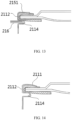
- the electrode assembly 22 may be first placed into the presealed housing body 215, the presealed housing body 215 is filled with an electrolyte, and then the cover 212 with the edge wrapped with the partial sealing ring 214 is placed at an opening of the presealed housing body 215 such that the edge of the cover 212 wrapped with the partial sealing ring 214 is on the second groove side wall 21143. Then, the to-be-bent housing wall 2151 is bent down to form the annular bent edge 2111, and finally a crimping force is applied to crimp the annular groove 2114.
- a force may be applied on an external side of an end of the to-be-bent housing wall 2151 away from the housing side wall 2112 to first bend the to-be-bent housing wall 2151 to be perpendicular to the housing side wall 2112, so that the presealed housing body 215 is in a first intermediate state shown in FIG. 13 .
- the magnitude of the force applied is, for example, 600 N to 800 N.
- the magnitude of the force is, for example, 100 N to 800 N, which is conducive to the design of 1° ⁇ (90° - ⁇ 2) ⁇ 25°
- the magnitude of the action force is, for example, 200 N to 500 N, which is conducive to the design of 5° ⁇ (90° - ⁇ 2) ⁇ 20°.
Landscapes
- Chemical & Material Sciences (AREA)
- Chemical Kinetics & Catalysis (AREA)
- Electrochemistry (AREA)
- General Chemical & Material Sciences (AREA)
- Engineering & Computer Science (AREA)
- Manufacturing & Machinery (AREA)
- Materials Engineering (AREA)
- Sealing Battery Cases Or Jackets (AREA)
- Battery Mounting, Suspending (AREA)
Applications Claiming Priority (2)
| Application Number | Priority Date | Filing Date | Title |
|---|---|---|---|
| CN202210763100.4A CN115051085B (zh) | 2022-06-30 | 2022-06-30 | 电池及其制造方法、电池模组以及用电设备 |
| PCT/CN2023/084153 WO2024001347A1 (fr) | 2022-06-30 | 2023-03-27 | Batterie, son procédé de fabrication, module de batterie et dispositif électrique |
Publications (2)
| Publication Number | Publication Date |
|---|---|
| EP4535523A1 true EP4535523A1 (fr) | 2025-04-09 |
| EP4535523A4 EP4535523A4 (fr) | 2025-11-26 |
Family
ID=83165943
Family Applications (1)
| Application Number | Title | Priority Date | Filing Date |
|---|---|---|---|
| EP23829538.0A Pending EP4535523A4 (fr) | 2022-06-30 | 2023-03-27 | Batterie, son procédé de fabrication, module de batterie et dispositif électrique |
Country Status (3)
| Country | Link |
|---|---|
| EP (1) | EP4535523A4 (fr) |
| CN (1) | CN115051085B (fr) |
| WO (1) | WO2024001347A1 (fr) |
Families Citing this family (4)
| Publication number | Priority date | Publication date | Assignee | Title |
|---|---|---|---|---|
| CN115051085B (zh) * | 2022-06-30 | 2024-04-02 | 东莞新能安科技有限公司 | 电池及其制造方法、电池模组以及用电设备 |
| CN120604385A (zh) * | 2023-11-01 | 2025-09-05 | 株式会社Lg新能源 | 具有增强密封的圆柱形电池 |
| KR102856630B1 (ko) * | 2023-11-01 | 2025-09-08 | 주식회사 엘지에너지솔루션 | 실링이 강화된 원통형 전지 |
| CN120749293B (zh) * | 2025-09-05 | 2025-11-18 | 蜂巢能源科技股份有限公司 | 电芯壳体及电芯 |
Family Cites Families (17)
| Publication number | Priority date | Publication date | Assignee | Title |
|---|---|---|---|---|
| JPH0950792A (ja) * | 1995-08-03 | 1997-02-18 | Fuji Photo Film Co Ltd | 円筒形電池の製造方法および装置 |
| JP3738230B2 (ja) * | 2002-01-15 | 2006-01-25 | 松下電器産業株式会社 | 電池の製造方法 |
| JP2005293922A (ja) * | 2004-03-31 | 2005-10-20 | Sanyo Electric Co Ltd | 電池およびその製造方法 |
| JP4748999B2 (ja) * | 2005-02-22 | 2011-08-17 | パナソニック株式会社 | 円筒形電池の封口方法 |
| JP5935013B2 (ja) * | 2012-02-24 | 2016-06-15 | パナソニックIpマネジメント株式会社 | 円筒形アルカリ蓄電池 |
| WO2016197563A1 (fr) * | 2015-06-12 | 2016-12-15 | 福建南平南孚电池有限公司 | Corps étanche d'une électrode négative d'un accumulateur |
| WO2018173453A1 (fr) * | 2017-03-24 | 2018-09-27 | パナソニックIpマネジメント株式会社 | Boîtier de batterie et batterie cylindrique |
| EP3637491B1 (fr) * | 2017-06-07 | 2023-11-01 | Murata Manufacturing Co., Ltd. | Batterie secondaire, bloc-batterie, véhicule électrique, système de stockage d'énergie, outil électrique, et appareil électronique |
| CN211404530U (zh) * | 2019-11-05 | 2020-09-01 | 东莞市沃泰通新能源有限公司 | 圆柱形电芯外壳封口结构及电芯 |
| JP7448031B2 (ja) * | 2020-10-21 | 2024-03-12 | 株式会社村田製作所 | 二次電池 |
| CN214378624U (zh) * | 2021-03-31 | 2021-10-08 | 蜂巢能源科技(无锡)有限公司 | 电池连接片安装结构、电池模组和电池 |
| CN113328213B (zh) * | 2021-04-27 | 2023-07-11 | 宁波超霸能源有限公司 | 圆柱型锂电池的制作方法 |
| CN214672780U (zh) * | 2021-04-27 | 2021-11-09 | 宁波超霸能源有限公司 | 圆柱型锂电池的封口结构及圆柱型锂电池 |
| CN214672781U (zh) * | 2021-04-27 | 2021-11-09 | 宁波超霸能源有限公司 | 圆柱型锂电池的封口结构及圆柱型锂电池 |
| CN113328198B (zh) * | 2021-05-27 | 2025-06-27 | 宁德新能源科技有限公司 | 电池及用电装置 |
| CN216085065U (zh) * | 2021-09-30 | 2022-03-18 | 宁德时代新能源科技股份有限公司 | 电池单体、电池以及用电装置 |
| CN115051085B (zh) * | 2022-06-30 | 2024-04-02 | 东莞新能安科技有限公司 | 电池及其制造方法、电池模组以及用电设备 |
-
2022
- 2022-06-30 CN CN202210763100.4A patent/CN115051085B/zh active Active
-
2023
- 2023-03-27 WO PCT/CN2023/084153 patent/WO2024001347A1/fr not_active Ceased
- 2023-03-27 EP EP23829538.0A patent/EP4535523A4/fr active Pending
Also Published As
| Publication number | Publication date |
|---|---|
| CN115051085B (zh) | 2024-04-02 |
| EP4535523A4 (fr) | 2025-11-26 |
| CN115051085A (zh) | 2022-09-13 |
| WO2024001347A1 (fr) | 2024-01-04 |
Similar Documents
| Publication | Publication Date | Title |
|---|---|---|
| EP4535523A1 (fr) | Batterie, son procédé de fabrication, module de batterie et dispositif électrique | |
| KR102885306B1 (ko) | 이차 전지 | |
| US12438219B2 (en) | Battery cell including end cap with protruding structure connecting to tab, method and system for manufacturing same, battery, and electrical device | |
| US20250070422A1 (en) | Pouch Type Battery Case and Apparatus for Manufacturing the Same, and Pouch Type Secondary Battery | |
| US20250087854A1 (en) | Battery cell, battery, and electric apparatus | |
| US9123926B2 (en) | Secondary battery with terminal plate | |
| KR20210076770A (ko) | 이차 전지용 전지 케이스 및 파우치 형 이차 전지 | |
| EP4576298A1 (fr) | Dispositif électrochimique et appareil électrique | |
| CN102035011B (zh) | 二次电池 | |
| US7687196B2 (en) | Prismatic battery and method for manufacturing the same | |
| CN221239682U (zh) | 圆柱电池、电池组及电子设备 | |
| CN223079311U (zh) | 转接片、二次电池及电子装置 | |
| EP4683101A1 (fr) | Élément de connexion, élément de batterie, batterie et dispositif électrique | |
| CN222940151U (zh) | 二次电池及电子装置 | |
| EP4648155A1 (fr) | Batterie et procédé de fabrication de la batterie | |
| CN221239714U (zh) | 二次电池、电池组及电子设备 | |
| CN222953317U (zh) | 二次电池、电池组及电子装置 | |
| EP4366049B1 (fr) | Ensemble capuchon d'extrémité, élément de batterie, module de batterie et dispositif électrique | |
| US12476333B2 (en) | Battery cell having conductive piece close to welding region | |
| EP4683024A2 (fr) | Batterie secondaire, ensemble batterie et dispositif électronique | |
| US12176571B2 (en) | Exhaust apparatus, battery cell, battery, and electric apparatus | |
| KR102955181B1 (ko) | 전지 셀 및 그의 제조 방법, 제조 시스템, 전지 및 전기 장치 | |
| US20250070377A1 (en) | Pressure relief device, battery cell, battery, electrical apparatus, and manufacturing method | |
| KR20250176846A (ko) | 이차전지 | |
| KR100669336B1 (ko) | 이차 전지 |
Legal Events
| Date | Code | Title | Description |
|---|---|---|---|
| STAA | Information on the status of an ep patent application or granted ep patent |
Free format text: STATUS: THE INTERNATIONAL PUBLICATION HAS BEEN MADE |
|
| PUAI | Public reference made under article 153(3) epc to a published international application that has entered the european phase |
Free format text: ORIGINAL CODE: 0009012 |
|
| STAA | Information on the status of an ep patent application or granted ep patent |
Free format text: STATUS: REQUEST FOR EXAMINATION WAS MADE |
|
| 17P | Request for examination filed |
Effective date: 20241230 |
|
| AK | Designated contracting states |
Kind code of ref document: A1 Designated state(s): AL AT BE BG CH CY CZ DE DK EE ES FI FR GB GR HR HU IE IS IT LI LT LU LV MC ME MK MT NL NO PL PT RO RS SE SI SK SM TR |
|
| DAV | Request for validation of the european patent (deleted) | ||
| DAX | Request for extension of the european patent (deleted) | ||
| A4 | Supplementary search report drawn up and despatched |
Effective date: 20251024 |
|
| RIC1 | Information provided on ipc code assigned before grant |
Ipc: H01M 50/167 20210101AFI20251020BHEP Ipc: H01M 50/107 20210101ALI20251020BHEP Ipc: H01M 10/04 20060101ALI20251020BHEP |