EP4535533A1 - Verriegelungsvorrichtung und fahrzeug - Google Patents
Verriegelungsvorrichtung und fahrzeug Download PDFInfo
- Publication number
- EP4535533A1 EP4535533A1 EP23811181.9A EP23811181A EP4535533A1 EP 4535533 A1 EP4535533 A1 EP 4535533A1 EP 23811181 A EP23811181 A EP 23811181A EP 4535533 A1 EP4535533 A1 EP 4535533A1
- Authority
- EP
- European Patent Office
- Prior art keywords
- seat body
- connection
- locking device
- rod
- pressing block
- Prior art date
- Legal status (The legal status is an assumption and is not a legal conclusion. Google has not performed a legal analysis and makes no representation as to the accuracy of the status listed.)
- Pending
Links
Images


Classifications
-
- B—PERFORMING OPERATIONS; TRANSPORTING
- B60—VEHICLES IN GENERAL
- B60T—VEHICLE BRAKE CONTROL SYSTEMS OR PARTS THEREOF; BRAKE CONTROL SYSTEMS OR PARTS THEREOF, IN GENERAL; ARRANGEMENT OF BRAKING ELEMENTS ON VEHICLES IN GENERAL; PORTABLE DEVICES FOR PREVENTING UNWANTED MOVEMENT OF VEHICLES; VEHICLE MODIFICATIONS TO FACILITATE COOLING OF BRAKES
- B60T17/00—Component parts, details, or accessories of power brake systems not covered by groups B60T8/00, B60T13/00 or B60T15/00, or presenting other characteristic features
- B60T17/08—Brake cylinders other than ultimate actuators
- B60T17/088—Mounting arrangements
-
- B—PERFORMING OPERATIONS; TRANSPORTING
- B60—VEHICLES IN GENERAL
- B60L—PROPULSION OF ELECTRICALLY-PROPELLED VEHICLES; SUPPLYING ELECTRIC POWER FOR AUXILIARY EQUIPMENT OF ELECTRICALLY-PROPELLED VEHICLES; ELECTRODYNAMIC BRAKE SYSTEMS FOR VEHICLES IN GENERAL; MAGNETIC SUSPENSION OR LEVITATION FOR VEHICLES; MONITORING OPERATING VARIABLES OF ELECTRICALLY-PROPELLED VEHICLES; ELECTRIC SAFETY DEVICES FOR ELECTRICALLY-PROPELLED VEHICLES
- B60L53/00—Methods of charging batteries, specially adapted for electric vehicles; Charging stations or on-board charging equipment therefor; Exchange of energy storage elements in electric vehicles
- B60L53/80—Exchanging energy storage elements, e.g. removable batteries
-
- B—PERFORMING OPERATIONS; TRANSPORTING
- B60—VEHICLES IN GENERAL
- B60K—ARRANGEMENT OR MOUNTING OF PROPULSION UNITS OR OF TRANSMISSIONS IN VEHICLES; ARRANGEMENT OR MOUNTING OF PLURAL DIVERSE PRIME-MOVERS IN VEHICLES; AUXILIARY DRIVES FOR VEHICLES; INSTRUMENTATION OR DASHBOARDS FOR VEHICLES; ARRANGEMENTS IN CONNECTION WITH COOLING, AIR INTAKE, GAS EXHAUST OR FUEL SUPPLY OF PROPULSION UNITS IN VEHICLES
- B60K1/00—Arrangement or mounting of electrical propulsion units
- B60K1/04—Arrangement or mounting of electrical propulsion units of the electric storage means for propulsion
-
- B—PERFORMING OPERATIONS; TRANSPORTING
- B60—VEHICLES IN GENERAL
- B60L—PROPULSION OF ELECTRICALLY-PROPELLED VEHICLES; SUPPLYING ELECTRIC POWER FOR AUXILIARY EQUIPMENT OF ELECTRICALLY-PROPELLED VEHICLES; ELECTRODYNAMIC BRAKE SYSTEMS FOR VEHICLES IN GENERAL; MAGNETIC SUSPENSION OR LEVITATION FOR VEHICLES; MONITORING OPERATING VARIABLES OF ELECTRICALLY-PROPELLED VEHICLES; ELECTRIC SAFETY DEVICES FOR ELECTRICALLY-PROPELLED VEHICLES
- B60L50/00—Electric propulsion with power supplied within the vehicle
- B60L50/50—Electric propulsion with power supplied within the vehicle using propulsion power supplied by batteries or fuel cells
- B60L50/60—Electric propulsion with power supplied within the vehicle using propulsion power supplied by batteries or fuel cells using power supplied by batteries
- B60L50/64—Constructional details of batteries specially adapted for electric vehicles
-
- H—ELECTRICITY
- H01—ELECTRIC ELEMENTS
- H01M—PROCESSES OR MEANS, e.g. BATTERIES, FOR THE DIRECT CONVERSION OF CHEMICAL ENERGY INTO ELECTRICAL ENERGY
- H01M50/00—Constructional details or processes of manufacture of the non-active parts of electrochemical cells other than fuel cells, e.g. hybrid cells
- H01M50/20—Mountings; Secondary casings or frames; Racks, modules or packs; Suspension devices; Shock absorbers; Transport or carrying devices; Holders
- H01M50/249—Mountings; Secondary casings or frames; Racks, modules or packs; Suspension devices; Shock absorbers; Transport or carrying devices; Holders specially adapted for aircraft or vehicles, e.g. cars or trains
-
- H—ELECTRICITY
- H01—ELECTRIC ELEMENTS
- H01M—PROCESSES OR MEANS, e.g. BATTERIES, FOR THE DIRECT CONVERSION OF CHEMICAL ENERGY INTO ELECTRICAL ENERGY
- H01M50/00—Constructional details or processes of manufacture of the non-active parts of electrochemical cells other than fuel cells, e.g. hybrid cells
- H01M50/20—Mountings; Secondary casings or frames; Racks, modules or packs; Suspension devices; Shock absorbers; Transport or carrying devices; Holders
- H01M50/262—Mountings; Secondary casings or frames; Racks, modules or packs; Suspension devices; Shock absorbers; Transport or carrying devices; Holders with fastening means, e.g. locks
-
- H—ELECTRICITY
- H01—ELECTRIC ELEMENTS
- H01M—PROCESSES OR MEANS, e.g. BATTERIES, FOR THE DIRECT CONVERSION OF CHEMICAL ENERGY INTO ELECTRICAL ENERGY
- H01M50/00—Constructional details or processes of manufacture of the non-active parts of electrochemical cells other than fuel cells, e.g. hybrid cells
- H01M50/20—Mountings; Secondary casings or frames; Racks, modules or packs; Suspension devices; Shock absorbers; Transport or carrying devices; Holders
- H01M50/262—Mountings; Secondary casings or frames; Racks, modules or packs; Suspension devices; Shock absorbers; Transport or carrying devices; Holders with fastening means, e.g. locks
- H01M50/264—Mountings; Secondary casings or frames; Racks, modules or packs; Suspension devices; Shock absorbers; Transport or carrying devices; Holders with fastening means, e.g. locks for cells or batteries, e.g. straps, tie rods or peripheral frames
-
- B—PERFORMING OPERATIONS; TRANSPORTING
- B60—VEHICLES IN GENERAL
- B60K—ARRANGEMENT OR MOUNTING OF PROPULSION UNITS OR OF TRANSMISSIONS IN VEHICLES; ARRANGEMENT OR MOUNTING OF PLURAL DIVERSE PRIME-MOVERS IN VEHICLES; AUXILIARY DRIVES FOR VEHICLES; INSTRUMENTATION OR DASHBOARDS FOR VEHICLES; ARRANGEMENTS IN CONNECTION WITH COOLING, AIR INTAKE, GAS EXHAUST OR FUEL SUPPLY OF PROPULSION UNITS IN VEHICLES
- B60K1/00—Arrangement or mounting of electrical propulsion units
- B60K1/04—Arrangement or mounting of electrical propulsion units of the electric storage means for propulsion
- B60K2001/0455—Removal or replacement of the energy storages
-
- B—PERFORMING OPERATIONS; TRANSPORTING
- B60—VEHICLES IN GENERAL
- B60Y—INDEXING SCHEME RELATING TO ASPECTS CROSS-CUTTING VEHICLE TECHNOLOGY
- B60Y2200/00—Type of vehicle
- B60Y2200/10—Road Vehicles
- B60Y2200/14—Trucks; Load vehicles, Busses
- B60Y2200/142—Heavy duty trucks
-
- F—MECHANICAL ENGINEERING; LIGHTING; HEATING; WEAPONS; BLASTING
- F16—ENGINEERING ELEMENTS AND UNITS; GENERAL MEASURES FOR PRODUCING AND MAINTAINING EFFECTIVE FUNCTIONING OF MACHINES OR INSTALLATIONS; THERMAL INSULATION IN GENERAL
- F16D—COUPLINGS FOR TRANSMITTING ROTATION; CLUTCHES; BRAKES
- F16D2127/00—Auxiliary mechanisms
- F16D2127/06—Locking mechanisms, e.g. acting on actuators, on release mechanisms or on force transmission mechanisms
-
- Y—GENERAL TAGGING OF NEW TECHNOLOGICAL DEVELOPMENTS; GENERAL TAGGING OF CROSS-SECTIONAL TECHNOLOGIES SPANNING OVER SEVERAL SECTIONS OF THE IPC; TECHNICAL SUBJECTS COVERED BY FORMER USPC CROSS-REFERENCE ART COLLECTIONS [XRACs] AND DIGESTS
- Y02—TECHNOLOGIES OR APPLICATIONS FOR MITIGATION OR ADAPTATION AGAINST CLIMATE CHANGE
- Y02T—CLIMATE CHANGE MITIGATION TECHNOLOGIES RELATED TO TRANSPORTATION
- Y02T10/00—Road transport of goods or passengers
- Y02T10/60—Other road transportation technologies with climate change mitigation effect
- Y02T10/70—Energy storage systems for electromobility, e.g. batteries
-
- Y—GENERAL TAGGING OF NEW TECHNOLOGICAL DEVELOPMENTS; GENERAL TAGGING OF CROSS-SECTIONAL TECHNOLOGIES SPANNING OVER SEVERAL SECTIONS OF THE IPC; TECHNICAL SUBJECTS COVERED BY FORMER USPC CROSS-REFERENCE ART COLLECTIONS [XRACs] AND DIGESTS
- Y02—TECHNOLOGIES OR APPLICATIONS FOR MITIGATION OR ADAPTATION AGAINST CLIMATE CHANGE
- Y02T—CLIMATE CHANGE MITIGATION TECHNOLOGIES RELATED TO TRANSPORTATION
- Y02T10/00—Road transport of goods or passengers
- Y02T10/60—Other road transportation technologies with climate change mitigation effect
- Y02T10/7072—Electromobility specific charging systems or methods for batteries, ultracapacitors, supercapacitors or double-layer capacitors
Definitions
- the disclosure relates to the technical field of vehicles, and in particular to a locking device and a vehicle.
- a battery swap mode of electric vehicles storage and charging of a large number of batteries are centralized in a centralized charging station, and battery swap operations of the electric vehicles is completed in a battery swap station. In this way, a charging wait time can be shortened while a battery swap and maintenance cost can be lowered.
- a primary objective of the disclosure is to provide a locking device and a vehicle, so that a compact structure, a small occupied space, higher mounting performance, and a wide application range are realized.
- a locking device is provided.
- the locking device includes:
- the locking device further includes an adapter push rod
- the adapter push rod includes a first adapter end and second adapter ends disposed corresponding one-to-one to the two connection rod assemblies, the first adapter end is fixedly connected with an action end of the driving source, and the two second adapter ends are pivoted with the corresponding connection rod assemblies.
- the adapter push rod is of a U-shaped structure
- the first adapter end is disposed at a bottom end of the U-shaped structure
- the second adapter ends are disposed at tops of two ends of an opening of the U-shaped structure.
- connection rod assembly includes:
- the driving unit further includes a first connection shaft, and two ends of the first connection shaft penetrate one ends of the second connection rods of the two connection rod assemblies and then are pivoted with the first connection rods of the two connection rod assemblies respectively.
- the pressing block is provided with a middle shaft hole
- the driving unit further includes: a second connection shaft, the second connection shaft is disposed in the middle shaft hole in a penetrating manner, and two ends of the second connection shaft are pivoted with the second connection rods of the two connection rod assemblies respectively.
- the pressing block is provided with a tail-end shaft hole, a mounting hinge pin is disposed in the tail-end shaft hole in a penetrating manner, and two ends of the mounting hinge pin are pivoted to the two support frames respectively.
- the base includes: a locating seat body; and a mounting seat body, the mounting seat body is disposed at an end portion of the locating seat body, an included angle is formed between the mounting seat body and the locating seat body, and the driving unit is disposed on the mounting seat body.
- the locating seat body includes a first seat body, a second seat body, and a third seat body that are sequentially connected, and included angles are formed between the first seat body and the mounting seat body as well as between the third seat body and the mounting seat body separately; and the first seat body and the third seat body are oppositely arranged, so as to delimit a weight reduction space among the first seat body, the second seat body, and the third seat body.
- a vehicle in another aspect, includes any locking device described as above; where the vehicle further includes a battery to be swapped and a battery swap base; and a driving source drives a pressing block to rotate about a pivot shaft between the pressing block and a base, so that the pressing block selectively presses the battery to be swapped against the battery swap base.
- the disclosure has the beneficial effects as follows:
- the driving source drives the connection rod assemblies to drive the pressing block to move.
- a locking force is enhanced, and the compatibility with other apparatuses is improved; and the driving source is fixedly arranged at the base, so that the locking device has a more compact structure and occupies a smaller space.
- the layout of the vehicle is optimized, and the safety is higher.
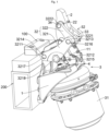
- connection rod assemblies 32 are provided, and the two connection rod assemblies 32 are symmetrically arranged on two sides of the pressing block 2 respectively, and the driving source is connected with the two connection rod assemblies 32, so that the driving source drives the two connection rod assemblies 32 to act synchronously. Accordingly, an overall bearing capacity and rigidity of the locking device can be improved, so that the locking force can be enhanced, and the service life can be prolonged.
- the locking device further includes an adapter push rod 4, the adapter push rod 4 includes a first adapter end 41 and second adapter ends 42 disposed corresponding one-to-one to the two connection rod assemblies 32, and the first adapter end 41 is fixedly connected with an action end of the driving source.
- the action end of the driving source is the push rod 311 of the air brake chamber 31, and the second adapter ends 42 are pivoted with the corresponding connection rod assemblies 32, so that the two connection rod assemblies 32 are driven to act synchronously through one adapter push rod 4.
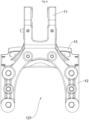
- the adapter push rod 4 is of a U-shaped structure
- the first adapter end 41 is disposed at a bottom end of the U-shaped structure
- the second adapter ends 42 are disposed at tops of two ends of an opening of the U-shaped structure.
- the adapter push rod 4 of the U-shaped structure is disposed matching the two connection rod assemblies 32, so that transmission of the connection rod assemblies 32 can be stabler, the overall bearing capacity and rigidity of the locking device can be improved, and the locking force can be enhanced accordingly.
- the adapter push rod 4 includes a first rod body, a second rod body, and a third rod body that are sequentially connected, and the first rod body and the third rod body are oppositely disposed; and the first adapter end 41 is disposed in a middle of the second rod body, and the two second adapter ends 42 are disposed at one end, away from the second rod body, of the first rod body and one end, away from the second rod body, of the third rod body separately.
- the first rod body, the second rod body, and the third rod body are of an integrally-formed U-shaped structure.
- connection rod assembly 32 includes a first connection rod 321 and a second connection rod 322;
- the first connection rod 321 includes a first end 3211, a second end 3212, and a third end 3213 that are sequentially disposed along a triangular track, the first end 3211 is pivoted with the base 1, and the second end 3212 is pivoted with the second corresponding adapter end 42; and one end of the second connection rod 322 is pivoted with the third end 3213, and the other end of the second connection rod is pivoted with the pressing block 2.
- the air brake chamber 31 is used to drive the connection rod assemblies 32, so as to drive the pressing block 2 to rotate, and the air brake chamber 31 is fixedly disposed at the base 1, so that the structure is simplified, and the occupied space is narrowed.
- the driving unit 3 further includes a first connection shaft 33, and two ends of the first connection shaft 33 penetrate one ends of the second connection rods 322 of the two connection rod assemblies 32 and then are pivoted with the first connection rods of the two connection rod assemblies 32 respectively.
- the two connection rod assemblies 32 are connected through the first connection shaft 33. Accordingly, the overall structural strength and bearing capacity are improved while synchronization of the two connection rod assemblies 32 is ensured.
- the first connection shaft 33 is disposed in the fourth shaft hole 3221 in a penetrating manner
- the second connection shaft 34 is disposed in the fifth shaft hole 3222 in a penetrating manner.
- a tail end of the pressing block 2 is provided with a tail-end shaft hole 21, a mounting hinge pin 23 is disposed in the tail-end shaft hole 21 in a penetrating manner, and two ends of the mounting hinge pin 23 are pivoted with the two support frames 11 respectively.
- the pressing block 2 is pivoted with the two support frames 11 through the mounting hinge pin 23, so that the pressing block 2 is supported stably.
- a middle of the pressing block 2 is provided with a middle shaft hole 22, and the second connection shaft 34 is disposed the middle shaft hole 22 in a penetrating manner.
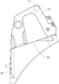
- the base 1 includes a locating seat body 12 and a mounting seat body 13 connected with one side of the locating seat body 12, where an included angle is formed between the mounting seat body 13 and the locating seat body 12, and the included angle is an obtuse angle.
- the two support frames 11 are both fixedly disposed at the mounting seat body 13.
- the driving source is fixedly arranged on one side, facing away from the pressing block 2, of the mounting seat body 13, and an axis of the driving source is perpendicular to the mounting seat body 13.
- the driving source is the air brake chamber 31, and in other words, the air brake chamber 31 is obliquely disposed on one side, facing away from the pressing block 2, of the mounting seat body 13. Compared with the prior art, a smaller space between the pressing block 2 and the mounting seat body 13 is occupied, and thus the layout of the member to be locked is not hindered.
- the mounting seat body 13 includes a bearing plate body, the first bearing end surface and the second bearing end surface are disposed on the bearing plate body, the bearing plate body is connected with the end portion of the locating seat body 12, and the included angle is formed between the bearing plate body and the locating seat body 12; and protecting plate bodies, two protecting plate bodies are provided, the two protecting plate bodies are arranged at two ends of the bearing plate body respectively, a mounting space is formed between the two protecting plate bodies, and at least part of the driving source is positioned in the mounting space.
- the locating seat body 12 includes a first seat body, a second seat body, and a third seat body that are sequentially connected, included angles are formed between the first seat body and the mounting seat body as well as between the third seat body and the mounting seat body separately; and the first seat body and the third seat body are oppositely disposed, so as to delimit a weight reduction space among the first seat body, the second seat body, and the third seat body.
- the mounting seat body 13 is provided with a through hole, and the push rod 311 of the air brake chamber 31 is disposed in the through hole in a penetrating manner, and extends and retracts in the through hole, so as to drive the pressing block 2 to rotate.
- the locating seat body 12 is provided with a weight reduction groove 121.
- the base 1 is provided with a reinforcing structure, so that the structural strength of the base 1 is improved.
- the locating seat body 12 and the mounting seat body 13 are both provided with reinforcing structures.
- a mounting structure is provided on one side, facing away from the mounting seat body 13, of the locating seat body 12.
- the locating seat body 12 can be fixedly mounted on a battery swap base 200, etc. of a vehicle by means of the mounting structure, so that the adaptability is high.
- a working process of the locking device in the example is as follows:
- the push rod 311 of the air brake chamber 31 is swing within an angle range of ⁇ 6°, so as to drive the adapter push rod 4 to drive the two first connection rods 321 to rotate about the first hinge pin 3217.
- the first connection rods 321 drive the second connection rods 322 to rotate, and the second connection rods 322 drive the pressing block 2 to rotate about the mounting hinge pin 23 until a free end of the pressing block 2 presses against the member to be locked, so that the member to be locked is locked.
- the push rod 311 of the air brake chamber 31 drives the adapter push rod 4 to drive the two first connection rods 321 to rotate about the first hinge pin 3217.
- the first connection rods 321 drive the second connection rods 322 to rotate, and the second connection rods 322 drive the pressing block 2 to rotate about the mounting hinge pin 23 until the free end of the pressing block 2 disengages from the member to be locked, so that the member to be locked is unlocked.
Landscapes
- Engineering & Computer Science (AREA)
- Mechanical Engineering (AREA)
- Transportation (AREA)
- Chemical & Material Sciences (AREA)
- Chemical Kinetics & Catalysis (AREA)
- Electrochemistry (AREA)
- General Chemical & Material Sciences (AREA)
- Power Engineering (AREA)
- Combustion & Propulsion (AREA)
- Life Sciences & Earth Sciences (AREA)
- Sustainable Development (AREA)
- Sustainable Energy (AREA)
- Aviation & Aerospace Engineering (AREA)
- Lock And Its Accessories (AREA)
- Pivots And Pivotal Connections (AREA)
Applications Claiming Priority (2)
| Application Number | Priority Date | Filing Date | Title |
|---|---|---|---|
| CN202221301459.1U CN217347473U (zh) | 2022-05-27 | 2022-05-27 | 一种锁紧装置及车辆 |
| PCT/CN2023/096559 WO2023227111A1 (zh) | 2022-05-27 | 2023-05-26 | 锁紧装置及车辆 |
Publications (2)
| Publication Number | Publication Date |
|---|---|
| EP4535533A1 true EP4535533A1 (de) | 2025-04-09 |
| EP4535533A4 EP4535533A4 (de) | 2025-09-17 |
Family
ID=83014972
Family Applications (1)
| Application Number | Title | Priority Date | Filing Date |
|---|---|---|---|
| EP23811181.9A Pending EP4535533A4 (de) | 2022-05-27 | 2023-05-26 | Verriegelungsvorrichtung und fahrzeug |
Country Status (5)
| Country | Link |
|---|---|
| US (1) | US20250296467A1 (de) |
| EP (1) | EP4535533A4 (de) |
| JP (1) | JP3251417U (de) |
| CN (1) | CN217347473U (de) |
| WO (1) | WO2023227111A1 (de) |
Families Citing this family (2)
| Publication number | Priority date | Publication date | Assignee | Title |
|---|---|---|---|---|
| CN217347473U (zh) * | 2022-05-27 | 2022-09-02 | 四川智锂智慧能源科技有限公司 | 一种锁紧装置及车辆 |
| CN115626045B (zh) * | 2022-10-24 | 2023-10-20 | 江苏众如金属科技有限公司 | 一种电动重卡电池箱锁止装置总成 |
Family Cites Families (7)
| Publication number | Priority date | Publication date | Assignee | Title |
|---|---|---|---|---|
| US5947018A (en) * | 1997-08-25 | 1999-09-07 | Unova Ip Corp. | Mechanical press with cam drive |
| CN215621511U (zh) * | 2021-09-08 | 2022-01-25 | 长沙杰立特自动化设备有限公司 | 一种重卡换电锁止机构 |
| CN115871428A (zh) * | 2021-09-27 | 2023-03-31 | 金茂智慧交通科技(天津)有限公司 | 锁止机构及车辆 |
| CN215971190U (zh) * | 2021-10-11 | 2022-03-08 | 无锡范特西物联技术有限公司 | 充放电底座锁紧装置 |
| CN114312459A (zh) * | 2021-12-23 | 2022-04-12 | 苏州睿锂物联科技有限公司 | 一种锁紧机构 |
| CN217347473U (zh) * | 2022-05-27 | 2022-09-02 | 四川智锂智慧能源科技有限公司 | 一种锁紧装置及车辆 |
| CN217672130U (zh) * | 2022-05-27 | 2022-10-28 | 四川智锂智慧能源科技有限公司 | 一种助力解锁机构及换电设备 |
-
2022
- 2022-05-27 CN CN202221301459.1U patent/CN217347473U/zh active Active
-
2023
- 2023-05-26 US US18/869,216 patent/US20250296467A1/en active Pending
- 2023-05-26 WO PCT/CN2023/096559 patent/WO2023227111A1/zh not_active Ceased
- 2023-05-26 JP JP2024600189U patent/JP3251417U/ja active Active
- 2023-05-26 EP EP23811181.9A patent/EP4535533A4/de active Pending
Also Published As
| Publication number | Publication date |
|---|---|
| JP3251417U (ja) | 2025-05-26 |
| EP4535533A4 (de) | 2025-09-17 |
| CN217347473U (zh) | 2022-09-02 |
| WO2023227111A1 (zh) | 2023-11-30 |
| US20250296467A1 (en) | 2025-09-25 |
Similar Documents
| Publication | Publication Date | Title |
|---|---|---|
| US20250296467A1 (en) | Locking Device and Vehicle | |
| CN212148389U (zh) | 一种锁止插销和电池锁止装置 | |
| US20230034860A1 (en) | Automotive Door Pedal | |
| CN111137341A (zh) | 一种集装卸运一体的无人机机翼托架 | |
| CN115284955A (zh) | 换电小车的车身定位组件及包含其的换电穿梭车 | |
| CN116533734A (zh) | 快换总成和换电车辆 | |
| CN217477126U (zh) | 换电小车的车身定位组件及包含其的换电穿梭车 | |
| CN219619108U (zh) | 一种牵车臂的牵车钩限位装置 | |
| CN220182691U (zh) | 一种搬运车及其电瓶锁紧装置 | |
| CN118477977A (zh) | 一种新能源汽车一体化压铸模的滑块分离小车 | |
| CN219770003U (zh) | 一种可伸缩车架的锁止结构 | |
| CN112573360B (zh) | 吊装系统及敞车中门吊装机构 | |
| CN218364873U (zh) | 一种搬运货物用机械手防脱落结构 | |
| CN213561541U (zh) | 驾驶型研磨机折叠踏板 | |
| CN113212069B (zh) | 一种车轴固定装置 | |
| CN211496831U (zh) | 全电动搬运车 | |
| CN220577360U (zh) | 锁紧装置及运输挂装一体车 | |
| CN222360804U (zh) | 移动机构及移动储能装置 | |
| CN211378488U (zh) | 一种用于固定通信机柜的加强固定装置 | |
| CN218877360U (zh) | 一种折叠托板 | |
| CN216713774U (zh) | 一种吊篮 | |
| CN213561540U (zh) | 驾驶型研磨机操作踏板 | |
| CN222522749U (zh) | 一种全地形车货箱 | |
| CN220341419U (zh) | 一种插拔式电池锁 | |
| CN220500483U (zh) | 一种电池包锁止机构及电动车辆 |
Legal Events
| Date | Code | Title | Description |
|---|---|---|---|
| STAA | Information on the status of an ep patent application or granted ep patent |
Free format text: STATUS: THE INTERNATIONAL PUBLICATION HAS BEEN MADE |
|
| PUAI | Public reference made under article 153(3) epc to a published international application that has entered the european phase |
Free format text: ORIGINAL CODE: 0009012 |
|
| STAA | Information on the status of an ep patent application or granted ep patent |
Free format text: STATUS: REQUEST FOR EXAMINATION WAS MADE |
|
| 17P | Request for examination filed |
Effective date: 20241122 |
|
| AK | Designated contracting states |
Kind code of ref document: A1 Designated state(s): AL AT BE BG CH CY CZ DE DK EE ES FI FR GB GR HR HU IE IS IT LI LT LU LV MC ME MK MT NL NO PL PT RO RS SE SI SK SM TR |
|
| DAV | Request for validation of the european patent (deleted) | ||
| DAX | Request for extension of the european patent (deleted) | ||
| A4 | Supplementary search report drawn up and despatched |
Effective date: 20250819 |
|
| RIC1 | Information provided on ipc code assigned before grant |
Ipc: H01M 50/244 20210101AFI20250812BHEP Ipc: H01M 50/264 20210101ALI20250812BHEP Ipc: B60L 53/80 20190101ALI20250812BHEP Ipc: B60K 1/04 20190101ALI20250812BHEP |