EP4535543A1 - Séparateur pour dispositif de stockage d'électricité et dispositif de stockage d'électricité le comprenant - Google Patents
Séparateur pour dispositif de stockage d'électricité et dispositif de stockage d'électricité le comprenant Download PDFInfo
- Publication number
- EP4535543A1 EP4535543A1 EP23811907.7A EP23811907A EP4535543A1 EP 4535543 A1 EP4535543 A1 EP 4535543A1 EP 23811907 A EP23811907 A EP 23811907A EP 4535543 A1 EP4535543 A1 EP 4535543A1
- Authority
- EP
- European Patent Office
- Prior art keywords
- weight
- particle size
- less
- separator
- covering layer
- Prior art date
- Legal status (The legal status is an assumption and is not a legal conclusion. Google has not performed a legal analysis and makes no representation as to the accuracy of the status listed.)
- Pending
Links
Images


Classifications
-
- H—ELECTRICITY
- H01—ELECTRIC ELEMENTS
- H01G—CAPACITORS; CAPACITORS, RECTIFIERS, DETECTORS, SWITCHING DEVICES, LIGHT-SENSITIVE OR TEMPERATURE-SENSITIVE DEVICES OF THE ELECTROLYTIC TYPE
- H01G11/00—Hybrid capacitors, i.e. capacitors having different positive and negative electrodes; Electric double-layer [EDL] capacitors; Processes for the manufacture thereof or of parts thereof
- H01G11/04—Hybrid capacitors
- H01G11/06—Hybrid capacitors with one of the electrodes allowing ions to be reversibly doped thereinto, e.g. lithium ion capacitors [LIC]
-
- H—ELECTRICITY
- H01—ELECTRIC ELEMENTS
- H01G—CAPACITORS; CAPACITORS, RECTIFIERS, DETECTORS, SWITCHING DEVICES, LIGHT-SENSITIVE OR TEMPERATURE-SENSITIVE DEVICES OF THE ELECTROLYTIC TYPE
- H01G11/00—Hybrid capacitors, i.e. capacitors having different positive and negative electrodes; Electric double-layer [EDL] capacitors; Processes for the manufacture thereof or of parts thereof
- H01G11/52—Separators
-
- H—ELECTRICITY
- H01—ELECTRIC ELEMENTS
- H01M—PROCESSES OR MEANS, e.g. BATTERIES, FOR THE DIRECT CONVERSION OF CHEMICAL ENERGY INTO ELECTRICAL ENERGY
- H01M10/00—Secondary cells; Manufacture thereof
- H01M10/05—Accumulators with non-aqueous electrolyte
- H01M10/052—Li-accumulators
- H01M10/0525—Rocking-chair batteries, i.e. batteries with lithium insertion or intercalation in both electrodes; Lithium-ion batteries
-
- H—ELECTRICITY
- H01—ELECTRIC ELEMENTS
- H01M—PROCESSES OR MEANS, e.g. BATTERIES, FOR THE DIRECT CONVERSION OF CHEMICAL ENERGY INTO ELECTRICAL ENERGY
- H01M50/00—Constructional details or processes of manufacture of the non-active parts of electrochemical cells other than fuel cells, e.g. hybrid cells
- H01M50/40—Separators; Membranes; Diaphragms; Spacing elements inside cells
- H01M50/409—Separators, membranes or diaphragms characterised by the material
- H01M50/411—Organic material
- H01M50/414—Synthetic resins, e.g. thermoplastics or thermosetting resins
-
- H—ELECTRICITY
- H01—ELECTRIC ELEMENTS
- H01M—PROCESSES OR MEANS, e.g. BATTERIES, FOR THE DIRECT CONVERSION OF CHEMICAL ENERGY INTO ELECTRICAL ENERGY
- H01M50/00—Constructional details or processes of manufacture of the non-active parts of electrochemical cells other than fuel cells, e.g. hybrid cells
- H01M50/40—Separators; Membranes; Diaphragms; Spacing elements inside cells
- H01M50/409—Separators, membranes or diaphragms characterised by the material
- H01M50/411—Organic material
- H01M50/414—Synthetic resins, e.g. thermoplastics or thermosetting resins
- H01M50/417—Polyolefins
-
- H—ELECTRICITY
- H01—ELECTRIC ELEMENTS
- H01M—PROCESSES OR MEANS, e.g. BATTERIES, FOR THE DIRECT CONVERSION OF CHEMICAL ENERGY INTO ELECTRICAL ENERGY
- H01M50/00—Constructional details or processes of manufacture of the non-active parts of electrochemical cells other than fuel cells, e.g. hybrid cells
- H01M50/40—Separators; Membranes; Diaphragms; Spacing elements inside cells
- H01M50/409—Separators, membranes or diaphragms characterised by the material
- H01M50/411—Organic material
- H01M50/414—Synthetic resins, e.g. thermoplastics or thermosetting resins
- H01M50/42—Acrylic resins
-
- H—ELECTRICITY
- H01—ELECTRIC ELEMENTS
- H01M—PROCESSES OR MEANS, e.g. BATTERIES, FOR THE DIRECT CONVERSION OF CHEMICAL ENERGY INTO ELECTRICAL ENERGY
- H01M50/00—Constructional details or processes of manufacture of the non-active parts of electrochemical cells other than fuel cells, e.g. hybrid cells
- H01M50/40—Separators; Membranes; Diaphragms; Spacing elements inside cells
- H01M50/409—Separators, membranes or diaphragms characterised by the material
- H01M50/431—Inorganic material
- H01M50/434—Ceramics
-
- H—ELECTRICITY
- H01—ELECTRIC ELEMENTS
- H01M—PROCESSES OR MEANS, e.g. BATTERIES, FOR THE DIRECT CONVERSION OF CHEMICAL ENERGY INTO ELECTRICAL ENERGY
- H01M50/00—Constructional details or processes of manufacture of the non-active parts of electrochemical cells other than fuel cells, e.g. hybrid cells
- H01M50/40—Separators; Membranes; Diaphragms; Spacing elements inside cells
- H01M50/409—Separators, membranes or diaphragms characterised by the material
- H01M50/431—Inorganic material
- H01M50/434—Ceramics
- H01M50/437—Glass
-
- H—ELECTRICITY
- H01—ELECTRIC ELEMENTS
- H01M—PROCESSES OR MEANS, e.g. BATTERIES, FOR THE DIRECT CONVERSION OF CHEMICAL ENERGY INTO ELECTRICAL ENERGY
- H01M50/00—Constructional details or processes of manufacture of the non-active parts of electrochemical cells other than fuel cells, e.g. hybrid cells
- H01M50/40—Separators; Membranes; Diaphragms; Spacing elements inside cells
- H01M50/409—Separators, membranes or diaphragms characterised by the material
- H01M50/443—Particulate material
-
- H—ELECTRICITY
- H01—ELECTRIC ELEMENTS
- H01M—PROCESSES OR MEANS, e.g. BATTERIES, FOR THE DIRECT CONVERSION OF CHEMICAL ENERGY INTO ELECTRICAL ENERGY
- H01M50/00—Constructional details or processes of manufacture of the non-active parts of electrochemical cells other than fuel cells, e.g. hybrid cells
- H01M50/40—Separators; Membranes; Diaphragms; Spacing elements inside cells
- H01M50/409—Separators, membranes or diaphragms characterised by the material
- H01M50/446—Composite material consisting of a mixture of organic and inorganic materials
-
- H—ELECTRICITY
- H01—ELECTRIC ELEMENTS
- H01M—PROCESSES OR MEANS, e.g. BATTERIES, FOR THE DIRECT CONVERSION OF CHEMICAL ENERGY INTO ELECTRICAL ENERGY
- H01M50/00—Constructional details or processes of manufacture of the non-active parts of electrochemical cells other than fuel cells, e.g. hybrid cells
- H01M50/40—Separators; Membranes; Diaphragms; Spacing elements inside cells
- H01M50/409—Separators, membranes or diaphragms characterised by the material
- H01M50/449—Separators, membranes or diaphragms characterised by the material having a layered structure
- H01M50/451—Separators, membranes or diaphragms characterised by the material having a layered structure comprising layers of only organic material and layers containing inorganic material
-
- H—ELECTRICITY
- H01—ELECTRIC ELEMENTS
- H01M—PROCESSES OR MEANS, e.g. BATTERIES, FOR THE DIRECT CONVERSION OF CHEMICAL ENERGY INTO ELECTRICAL ENERGY
- H01M50/00—Constructional details or processes of manufacture of the non-active parts of electrochemical cells other than fuel cells, e.g. hybrid cells
- H01M50/40—Separators; Membranes; Diaphragms; Spacing elements inside cells
- H01M50/46—Separators, membranes or diaphragms characterised by their combination with electrodes
-
- H—ELECTRICITY
- H01—ELECTRIC ELEMENTS
- H01M—PROCESSES OR MEANS, e.g. BATTERIES, FOR THE DIRECT CONVERSION OF CHEMICAL ENERGY INTO ELECTRICAL ENERGY
- H01M50/00—Constructional details or processes of manufacture of the non-active parts of electrochemical cells other than fuel cells, e.g. hybrid cells
- H01M50/40—Separators; Membranes; Diaphragms; Spacing elements inside cells
- H01M50/463—Separators, membranes or diaphragms characterised by their shape
-
- H—ELECTRICITY
- H01—ELECTRIC ELEMENTS
- H01M—PROCESSES OR MEANS, e.g. BATTERIES, FOR THE DIRECT CONVERSION OF CHEMICAL ENERGY INTO ELECTRICAL ENERGY
- H01M50/00—Constructional details or processes of manufacture of the non-active parts of electrochemical cells other than fuel cells, e.g. hybrid cells
- H01M50/40—Separators; Membranes; Diaphragms; Spacing elements inside cells
- H01M50/489—Separators, membranes, diaphragms or spacing elements inside the cells, characterised by their physical properties, e.g. swelling degree, hydrophilicity or shut down properties
-
- H—ELECTRICITY
- H01—ELECTRIC ELEMENTS
- H01G—CAPACITORS; CAPACITORS, RECTIFIERS, DETECTORS, SWITCHING DEVICES, LIGHT-SENSITIVE OR TEMPERATURE-SENSITIVE DEVICES OF THE ELECTROLYTIC TYPE
- H01G9/00—Electrolytic capacitors, rectifiers, detectors, switching devices, light-sensitive or temperature-sensitive devices; Processes of their manufacture
- H01G9/004—Details
- H01G9/02—Diaphragms; Separators
-
- Y—GENERAL TAGGING OF NEW TECHNOLOGICAL DEVELOPMENTS; GENERAL TAGGING OF CROSS-SECTIONAL TECHNOLOGIES SPANNING OVER SEVERAL SECTIONS OF THE IPC; TECHNICAL SUBJECTS COVERED BY FORMER USPC CROSS-REFERENCE ART COLLECTIONS [XRACs] AND DIGESTS
- Y02—TECHNOLOGIES OR APPLICATIONS FOR MITIGATION OR ADAPTATION AGAINST CLIMATE CHANGE
- Y02E—REDUCTION OF GREENHOUSE GAS [GHG] EMISSIONS, RELATED TO ENERGY GENERATION, TRANSMISSION OR DISTRIBUTION
- Y02E60/00—Enabling technologies; Technologies with a potential or indirect contribution to GHG emissions mitigation
- Y02E60/10—Energy storage using batteries
Definitions
- an electricity storage device includes a positive electrode, a negative electrode, and a microporous membrane separator between them.
- the separator has the function of preventing direct contact between the positive electrode and the negative electrode and allowing ions to permeate through the electrolyte solution held in the micropores thereof.
- the separator is required to have safety performance such as a characteristic to quickly stop the battery reaction at the time of abnormal heating (fuse characteristics), and performance to maintain its shape even at high temperatures and prevent dangerous situations in which the positive electrode and the negative electrode directly react (short-circuit resistance characteristics).
- Patent Literature 3 describes a water-based coating material for separators comprising an adhesive containing two types of particulate polymers, and inorganic particles. Patent Literature 3 further describes that a separator using the water-based coating material has suitable air permeability and blocking resistance, is easy to wind and store, and has a long circulation storage life.
- Patent Literature 4 describes a separator comprising a non-aqueous secondary battery adhesive layer for providing a separator which provides excellent blocking resistance in the adhesive layer and excellent low-temperature output characteristics in secondary batteries.
- Patent Literature 4 describes a separator comprising a nonaqueous secondary battery adhesive layer, it is merely described that this adhesive layer comprises a binder and two types of particulate polymers the volume average particle diameters of which fall within a specific range.
- the separator for an electricity storage device of the present embodiment comprises a substrate which is a polyolefin microporous membrane comprising a polyolefin as a primary component, and a covering layer arranged on at least one surface of the substrate.
- the covering layer comprises an inorganic filler and a particulate polymer that is a thermoplastic polymer.
- the separator for an electricity storage device of the present embodiment preferably has one or more of the following features (1) to (3):
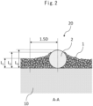
- the upper limit of the coverage rate (L2-L1) / (L3-L1) is preferably less than 1.0 (for example, 1.00), 0.9 (for example, 0.90) or less, 0.8 (for example, 0.80) or less, or 0.7 (for example, 0.70) or less.
- a coverage rate of 1.0 or more means that the inorganic filler on the protruding portion of the particulate polymer reaches the top of the contour of the protruding particulate polymer (the point farthest from the boundary line between the substrate and the covering layer).
- the coverage rate is less than 1.0, the contact area between the particulate polymer and the electrodes is secured, and the adhesive strength with the electrodes is increased.
- the coverage rate is 0.8 or less, the contact area between the particulate polymer and the electrodes is increased, and the adhesive strength with the electrodes is increased.
- the separator for an electricity storage device has a 180° peel strength of preferably 200 gf/cm or more, more preferably 230 gf/cm or more, and further preferably 250 gf/cm or more.
- the "180° peel strength" is the strength when the covering layer is peeled off so that the surface of the covering layer facing the substrate forms an angle of 180° with the substrate.
- the upper limit of the 180° peel strength may be 500 gf/cm or less.
- the separator for an electricity storage device of the present embodiment has any combination of the above features (1) to (3), i.e.: (1) and (2); (1) and (3); (2) and (3); and (1), (2), and (3).
- the combination of (1), (2), and (3) is preferable, and specifically, it is preferable that the covering layer be formed in a gradient shape so as to become thicker toward the protruding particulate polymer, the contact ratio between the protruding particulate polymer and the surface of the substrate be 20% or more, and the 180° peel strength be 200 gf/cm or more.
- the distribution of the protruding particulate polymer is highly uniform, and thus, the distribution of the region between the protruding particulate polymers is also highly uniform.
- the uniformity of the in-plane distribution of lithium-ion migration through the region between the electrodes can be improved, and thus, the rate characteristics and/or cycle characteristics can be improved.
- a magnification appropriate for the analysis by Voronoi division is set in accordance with the particle diameter of the thermoplastic polymer particles. Specifically, the magnification is set so that the number of thermoplastic polymer particles observed in one field of view is preferably 40 or more and 300 or less, more preferably 60 or more and 240 or less, and further preferably 80 or more and 200 or less. This allows the analysis by Voronoi division to be appropriately performed.
- thermoplastic polymer particles having a particle size of approximately 2.0 ⁇ m is approximately 10 parts by weight relative to 100 parts by weight of the inorganic filler of the covering layer
- a magnification of 5000-fold is appropriate
- the content of thermoplastic polymer particles having a particle size of approximately 3.5 ⁇ m is approximately 10 parts by weight relative to 100 parts by weight of the inorganic filler of the covering layer
- a magnification of approximately 1000-fold is appropriate for the analysis by Voronoi division.
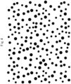
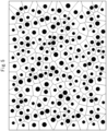
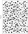
- the protruding particulate polymers identified by observing the surface of the covering layer can be subjected to Voronoi division as defined above. Specifically, the surface of the coating film after the substrate is coated with a coating liquid containing a thermoplastic polymer is photographed to obtain an image.
- the protruding portions of the protruding particulate polymers identified in the obtained image can be regarded as a circle having an average diameter (1 (L) and subjected to Voronoi division to draw Voronoi polygons.
- the Voronoi polygons may be drawn manually or using image processing software. The areas (s i ) of the drawn Voronoi polygons are calculated.
- the particle size distribution of the particulate polymer has two or more particle sizes.
- the particle size distribution of the particulate polymer protruding from the surface of the inorganic filler portion have two or more particle sizes.
- the particle size distribution having a particle size refers to having a particle size peak in a specific range.
- having a particle size peak includes having a shoulder.
- the particle size distribution of the particulate polymer has two or more particle size peaks in specific ranges.
- the particle size distribution of the particulate polymer has a first particle size peak in the range of 1.0-fold or more and 2.0-fold or less the thickness of the inorganic portion of the covering layer. It is preferable that the particle size distribution have a second particle size peak in a range larger than the first particle size peak, and that the particle size of the second particle size peak be 0.5 ⁇ m or more larger than the particle size of the first particle size peak.
- the first particle size peak is more preferably in the range of 1.1-fold or more and 1.7-fold or less the thickness of the inorganic portion of the covering layer, and further preferably in the range of 1.2-fold or more and 1.5-fold or less.
- a separator for an electricity storage device having feature (5) when the particle size distribution of the particulate polymer has particle size peaks within these specific ranges, for example, in the production of the separator for an electricity storage device or the electricity storage device, the adhesive strength and spacer effect of the separator for an electricity storage device can be compatible, and deformation of the electrode wound body can be suppressed, thereby improving cell life.
- the particle size of the fourth particle size peak be 0.5 ⁇ m, 0.6 ⁇ m, 0.7 ⁇ m, 0.8 ⁇ m, 0.9 ⁇ m, or 1.0 ⁇ m or more larger than the particle size of the third particle size peak.
- the particle size of the fourth particle size peak be 5.0 ⁇ m, 4.5 ⁇ m, 4.0 ⁇ m, 3.0 ⁇ m, 2.5 ⁇ m, 2.0 ⁇ m or less, or less than 2.0 ⁇ m larger than the particle size of the third particle size peak.
- the first Tg is more preferably 20°C or higher and 95°C or lower, and further preferably 30°C or higher and 70°C or lower. From the viewpoint of further improving the dry adhesive strength, the first Tg is preferably 10°C or higher and 60°C or lower, 50°C or lower, 40°C or lower, 30°C or lower, 20°C or lower, or lower than 20°C.
- the second Tg is preferably 70°C or higher, 80°C or higher, 90°C or higher, higher than 90°C, 95°C or higher, 100°C or higher, or higher than 100°C.
- a separator comprising a covering layer composed of a combination of these particulate polymers suppresses blocking of the first particulate polymer due to the gaps created by the second particulate polymer, thereby improving adhesive strength (in particular, dry adhesive strength) and blocking resistance during winding or during production of an electricity storage device, thereby suppressing deformation of the wound body and improving cell life.
- the coefficient of static friction of the covering layer is 0.10 or more and less than 0.40.
- the coefficient of static friction of the covering layer is within this range, for example, in the production of a cylindrical electricity storage device, it is possible to prevent pin removal failure (for example, a phenomenon in which the separator misaligns and forms layers resembling bamboo shoots when the pin is removed) from a wound body obtained by winding the separator for an electricity storage device around a pin, and/or it is possible to easily insert the wound body into a device exterior body such as a cylindrical housing, thereby improving the productivity of the electricity storage device such as a cell.
- pin removal failure for example, a phenomenon in which the separator misaligns and forms layers resembling bamboo shoots when the pin is removed
- the coefficient of static friction of the covering layer is preferably 0.14 or more and 0.39 or less, more preferably 0.20 or more and 0.39 or less, further preferably 0.24 or more and 0.39 or less, and particularly preferably 0.30 or more and 0.39 or less.
- the particulate polymer protruding from the surface of the inorganic filler portion contained in the covering layer is preferably composed of a thermoplastic polymer, whereby the shape of the protruding portion can easily be maintained.
- the shape of the protruding portion composed of a thermoplastic polymer can easily be maintained, the particulate polymer is less likely to be crushed, whereby the conformability of the separator with other members is suppressed, and thus, for example, when removing a pin from the separator wound body, pin removal failure is less likely to occur.
- examples of means for controlling the conditions of the coating and drying steps include adjusting the viscosity of the coating liquid to be applied to the substrate to within a predetermined range; increasing the particle size distribution of the thermoplastic polymer in the coating liquid; etc.
- examples of means for controlling the conditions after the coating and drying steps include controlling the tension applied in the direction perpendicular to the surface where the coated surface contacts the transport roller to a predetermined value or less; setting the speed of the transport roller with which the coated surface contacts equal to the separator transport speed; and increasing the peel strength of the covering layer.
- the methylene chloride soluble content is preferably 0.05% by weight or more and 0.80% by weight or less, more preferably 0.10% by weight or more and 0.60% by weight or less, and further preferably 0.15% by weight or more and 0.50% by weight or less, based on the total weight of the separator for an electricity storage device.
- the "soluble content" of methylene chloride means the component extracted into methylene chloride when the separator is immersed in methylene chloride.
- the plasticizer mixed when producing the substrate is mainly extracted as the methylene chloride soluble content.
- the TD thermal shrinkage rate at 150°C for 1 hour is preferably 5% or less, more preferably 0% or more and 3% or less, and further preferably 0% or more and 1% or less.
- the TD thermal shrinkage rate is 5% or less, it is possible to more effectively suppress the occurrence of short circuits in locations other than the location to which an external force is applied when heat is generated due to short circuit during a crash test. This makes it possible to more reliably prevent temperature rise of the entire battery, and the smoke and fire that may occur as a result.
- the polyolefin microporous membrane has an air permeability of 500 sec/100 cm 3 or less and a post-compression porosity of 30% or more within a membrane thickness range of 1 ⁇ m to 30 ⁇ m, for example, in the production of a nonaqueous secondary battery using a polyolefin microporous membrane as a separator, the electrical resistance of the polyolefin microporous membrane can be reduced or an increase in electrical resistance can be suppressed after a pressing step, whereby high output and high cycle characteristics of the nonaqueous secondary battery can be achieved.
- the suppression of the increase in resistance by the polyolefin microporous membrane is remarkable when an electrode that easily expands and contracts in the cell of the nonaqueous secondary battery is used, and is more remarkable when a high-capacity electrode used in an on-board battery or a silicon (Si)-containing negative electrode is used.
- the post-compression porosity is considered to be related to the structure of the primary component of the polyolefin microporous membrane, which reduces the resistance and/or suppresses the increase in resistance in non-aqueous secondary batteries.
- the post-compression porosity of the polyolefin microporous membrane is preferably 31% or more, more preferably 32% or more, and further preferably 33% or more.
- the upper limit of the post-compression porosity of the polyolefin microporous membrane can be determined in accordance with the porosity before compression, and may be, for example, preferably 60% or less, and more preferably 50% or less.
- the post-compression porosity of the polyolefin microporous membrane can be adjusted within the above-described numerical range in, for example, the production process of the polyolefin microporous membrane by controlling the molecular weight of the polyolefin raw material, the molecular weight and content of the polyethylene raw material, the stretching ratio in the biaxial stretching step, the preheating coefficient in the biaxial stretching step, the stretching coefficient in the biaxial stretching step, the MD/TD stretching temperature in the biaxial stretching step, the heat setting temperature, etc.
- the post-compression porosity of the polyolefin microporous membrane can be adjusted within the above-described numerical range by controlling the molecular weight of the polyolefin raw material, the molecular weight and content of the polyethylene raw material, the stretching ratio in the biaxial stretching step, the preheating coefficient in the biaxial stretching step, the stretching coefficient in the biaxial stretching step, the ratio of the preheating coefficient to the stretching coefficient, etc.
- porosity it is preferable to compare the porosity of the polyolefin microporous membrane before and after the compression test in order to specify the structure of the primary component of the membrane that can reduce the resistance and/or suppress the increase in resistance in a non-aqueous secondary battery and achieve high output and high cycle characteristics.
- the preferable numerical range of the porosity of the polyolefin microporous membrane before the compression test or not subjected to the compression test (hereinafter simply referred to as "porosity") is described later.
- the nonaqueous secondary battery can achieve high output and high cycle characteristics even after the pressing step in the production of the nonaqueous secondary battery using the polyolefin microporous membrane as a separator.
- the crystal long-period of the polyolefin microporous membrane can be adjusted within the above-described numerical range by controlling, for example, the molecular weight of the polyolefin raw material, the molecular weight and content of the polyethylene raw material, the stretching ratio in the biaxial stretching step, the preheating coefficient in the biaxial stretching step, the stretching coefficient in the biaxial stretching step, the MD/TD stretching temperature in the biaxial stretching step, the heat setting temperature, etc., in the production process of the polyolefin microporous membrane.
- the substrate may contain other resins besides polyolefins, such as polyethylene terephthalate, polycycloolefin, polyethersulfone, polyamide, polyimide, polyimideamide, polyaramid, polycycloolefin, nylon, and polytetrafluoroethylene.
- polyolefins such as polyethylene terephthalate, polycycloolefin, polyethersulfone, polyamide, polyimide, polyimideamide, polyaramid, polycycloolefin, nylon, and polytetrafluoroethylene.
- plasticizers examples include hydrocarbons such as liquid paraffin, esters such as dioctyl phthalate and dibutyl phthalate, and higher alcohols such as oleyl alcohol and stearyl alcohol.
- the plasticizer is preferably liquid paraffin.
- the membrane density can be calculated assuming 0.95 g/cm 3 .
- the porosity can be adjusted by changing the stretching ratio of the polyolefin microporous membrane.
- the type, molecular weight, and composition of the polyolefin resin constituting the polyolefin microporous membrane can be adjusted, for example, by controlling the type, molecular weight, and blending ratio of polymer raw materials such as polyolefin in the production process of the polyolefin microporous membrane.
- the adjustment can be made as described above.
- the lower limit of the average particle size of the inorganic filler is preferably 50 nm or more, 100 nm or more, 150 nm or more, 200 nm or more, 250 nm or more, 300 nm or more, 350 nm or more, or 400 nm or more, and the upper limit is preferably 2000 nm or less, 1100 nm or less, 800 nm or less, 450 nm or less, 400 nm or less, 350 nm or less, or 300 nm or less.
- the coefficient of variation of the particle size distribution of the inorganic filler is preferably 0.55 or less, more preferably 0.50 or less, and further preferably 0.45 or less. It is preferable that the coefficient of variation of the particle size distribution be 0.55 or less from the viewpoint of suppressing deformation at temperatures exceeding the melting point of the substrate, and from the viewpoint of improving the gradient ratio of the covering layer and increasing the adhesive strength with the electrode.
- the particle size distribution of the inorganic filler which is obtained by dividing the standard deviation SD value of the volume average particle size of the inorganic filler by the value of D50, is preferably 0.55 or less, more preferably 0.50 or less, and further preferably 0.45 or less.
- a particle size distribution of 0.55 or less is preferable from the viewpoint of suppressing deformation at temperatures exceeding the melting point of substrate, and from the viewpoint of improving the gradient ratio of covering layer and increasing the adhesive strength with electrode.
- the reason why the gradient ratio increases when the particle size distribution of the inorganic filler is 0.55 or less is considered to be that the uniformity of particles is increased, and the contact ratio between particles is improved, whereby a laminated structure is more likely to form.
- the amount of the inorganic filler relative to the total weight of the covering layer is, for example, 20 parts by weight or more and less than 100 parts by weight, 30 parts by weight or more and 80 parts by weight or less, 35 parts by weight or more and 70 parts by weight or less, or further 40 parts by weight or more and 60 parts by weight or less.
- the Tg of the particulate polymer is preferably 110°C or lower from the viewpoint of obtaining suitable adhesive strength with the electrodes.
- the Tg of the particulate polymer can be appropriately adjusted by, for example, changing the type of the monomer used in the production of the particulate polymer and the blending ratio of each monomer when the particulate polymer is a copolymer.
- the glass transition temperature can be roughly estimated from the generally-stated Tg of the homopolymer (for example, as described in the " Polymer Handbook" (A Wiley-Interscience Publication )) and the blending ratio of the monomers.
- each particulate polymer is likely to form a structure protruding from the surface of the covering layer, which increases the adhesive strength with the electrodes and suppressing thermal shrinkage.
- the average particle size of the primary particles of the second particulate polymer contained in the covering layer is preferably 1.5 ⁇ m or more and 10.0 ⁇ m or less, more preferably 1.5 ⁇ m or more and 5.0 ⁇ m or less, further preferably 2.0 ⁇ m or more and less than 5.0 ⁇ m, and even further preferably 2.0 ⁇ m or more and 3.5 ⁇ m or less.
- (meth)acrylic acid aryl ester is phenyl (meth)acrylate.
- polyvinyl alcohol-based resins examples include polyvinyl alcohol and polyvinyl acetate.
- Examples of monomers having two or more radically polymerizable double bonds include divinylbenzene and polyfunctional (meth)acrylates, and polyfunctional (meth)acrylates are preferable.
- the resin of the resin binder include polyolefins such as polyethylene and polypropylene; fluorine-containing resins such as polyvinylidene fluoride and polytetrafluoroethylene; fluorine-containing rubbers such as vinylidene fluoride-hexafluoropropylene-tetrafluoroethylene copolymers and ethylene-tetrafluoroethylene copolymers; rubbers such as styrene-butadiene copolymers and hydrogenated products thereof, acrylonitrile-butadiene copolymers and hydrogenated products thereof, acrylonitrile-butadiene-styrene copolymers and hydrogenated products thereof, methacrylate-acrylate copolymers, styrene-acrylate copolymers, acrylonitrile-acrylate copolymers, ethylene propylene rubbers, polyvinyl alcohol, and polyvinyl acetate; cellulose derivatives such as ethyl cellulose
- the resin binder may comprise, for example, a resin latex binder.
- a resin latex binder for example, a copolymer of an unsaturated carboxylic acid monomer and another monomer copolymerizable therewith may be used.
- examples of aliphatic conjugated diene monomers include butadiene and isoprene
- examples of unsaturated carboxylic acid monomers include (meth)acrylic acid
- examples of other monomers include styrene.
- resin binder examples include the following (1) to (7):
- the volume average particle size (D50) thereof may be, for example, 50 nm or more and 500 nm or less, 60 nm or more and 460 nm or less, or 80 nm or more and 250 nm or less.
- the volume average particle size of the resin binder can be controlled by, for example, adjusting the polymerization time, polymerization temperature, raw material composition ratio, raw material charging order, pH, etc.
- the glass transition temperature of the resin binder is preferably 25°C or lower, more preferably 10°C or lower, and further preferably -15°C or lower. From the viewpoint of transparency, the glass transition temperature of the resin binder is preferably -60°C or higher.
- the volume average particle size (D50) of the resin binder is preferably 1-fold or more, more preferably 2-fold or more, and further preferably 2.5-fold or more the average pore size of the polyolefin microporous membrane from the viewpoint of improving the 180° peel strength.
- the volume average particle size (D50) of the resin binder is preferably 10-fold or less the average pore size of the polyolefin microporous membrane.
- anionic polymer examples include modified starches such as carboxymethyl starch and starch phosphate; anionic cellulose derivatives such as carboxymethyl cellulose; ammonium salts or alkali metal salts of polyacrylic acid; gum arabic; carrageenan; sodium chondroitin sulfate; sulfonic acid compounds such as sodium polystyrene sulfonate, sodium polyisobutylene sulfonate, and naphthalene sulfonic acid condensate salts; and polyethyleneimine xanthate salts.
- the ammonium salt or alkali metal salt of polyacrylic acid refers to a polymer in which at least one of the -COO- moieties derived from multiple carboxylic acid groups forms a salt with an ammonium ion or an alkali metal ion, such as a sodium ion (Na + ) or a potassium ion (K + ).
- Examples of the monomer (Ci) having one ammonium salt or alkali metal salt of a carboxylic acid include sodium (meth)acrylate and ammonium (meth)acrylate.
- Examples of the monomer copolymerizable with the monomer (Ci) or the monomer (C ii ) include (meth)acrylamides; ethylenically unsaturated dicarboxylic acids such as fumaric acid, maleic acid, itaconic acid, and citraconic acid; and ethylenically unsaturated dicarboxylic anhydrides such as maleic anhydride, itaconic anhydride, and citraconic anhydride.
- ammonium salt or alkali metal salt of polyacrylic acid described in (I) to (III) above may overlap with each other. It is desirable that the ammonium salt or alkali metal salt of polyacrylic acid described in (I) to (III) above have a small content of polyvalent cations when dissolved in water. Examples of polyvalent cations include magnesium ions, calcium ions, and iron ions. By reducing the content of these ions, the dispersibility of the particulate polymer in the mixed slurry with the particulate polymer is stabilized.
- cationic polymers include cationic starch; chitosan; gelatin; homopolymers or copolymers of quaternary salts of dimethylaminoethyl (meth)acrylate; homopolymers or copolymers of dimethylallylammonium chloride; polyamidines and copolymers thereof; polyvinylimidazoline; dicyandiamide-based condensates; epichlorohydrin-dimethylamine condensates; and polyethyleneimine.
- alkyl group having 1 or more and 10 or fewer carbon atoms may be linear, branched, or cyclic, and include a methyl group, an ethyl group, an n-propyl group, an isopropyl group, an n-butyl group, a sec-butyl group, a tert-butyl group, an n-pentyl group, an n-hexyl group, an n-heptyl group, an n-octyl group, an n-nonyl group, and an n-decyl group.
- Polyether surfactants are also available as commercially available products, and examples of such commercially available products include E-D052, E-D054, and E-F010 (manufactured by San Nopco Ltd.).
- the silicone surfactant may be linear, branched, or cyclic, as long as it contains at least a silicone chain, and may contain either a hydrophobic group or a hydrophilic group.
- hydrophilic group examples include amino groups, thiol groups, hydroxyl groups, alkoxy groups, carboxylic acid, sulfonic acid, phosphoric acid, nitric acid, and organic or inorganic salts thereof, ester groups, aldehyde groups, glycerol groups, and heterocyclic groups.
- Silicone-based surfactants are also available as commercial products, and examples of such commercial products include BYK-300, BYK-301, BYK-302, BYK-306, BYK-307, BYK-310, BYK-313, BYK-320, BYK-333, BYK-341, BYK-345, BYK-346, BYK-347, BYK-348, BYK-349 (all trade names, manufactured by BYK Japan KK), KM-80, KF-351A, KF-352A, KF-353, KF-354L, KF-355A, KF-615A, KF-945, KF-640, KF-642, KF-643, KF-6020, X-22-4515, KF-6011, KF-6012, KF-6015, KF-6017 (all trade names, manufactured by Shin-Etsu Chemical Co., Ltd.), SH-28PA, SH8400, SH-190, SF-8428 (all trade
- the amount of the covering layer be equal to or greater than the lower limit from the viewpoint improving the adhesive strength between the covering layer and the electrodes and suppressing thermal shrinkage. It is preferable that the amount of the covering layer be equal to or less than the upper limit from the viewpoint suppressing a decrease in ion permeability.
- any known production method can be used as the method for the production of the substrate, for example, either a wet porosity method or a dry porosity method.
- Example of the wet porosity method include, in the case where the substrate is a polyolefin microporous membrane, a method in which a polyolefin resin composition and a plasticizer are melt-kneaded to form a sheet, which is then optionally stretched, and the plasticizer is extracted to make the membrane porous; a method in which a polyolefin resin composition comprising a polyolefin resin as a primary component is melt-kneaded, extruded at a high draw ratio, and then heat-treated and stretched to peel the polyolefin crystal interface to make the membrane porous; a method in which a polyolefin resin composition and an inorganic filler are melt-kneaded to form a sheet, and then stretched and the interface between the polyolefin and the inorganic filler is peeled to
- plasticizer examples include hydrocarbons such as liquid paraffin and paraffin wax; esters such as dioctyl phthalate and dibutyl phthalate; and higher alcohols such as oleyl alcohol and stearyl alcohol. Among these, liquid paraffin is preferable.
- the molten kneaded product obtained by heating, melting, and kneading as described above is molded into a sheet.
- the method for producing a sheet-like molded product include a method in which the molten kneaded product is extruded into a sheet shape through a T-die or the like, and is brought into contact with a thermal conductor to cool to a temperature sufficiently lower than the crystallization temperature of the resin component to solidify.
- thermal conductors used for cooling and solidifying include metal, water, air, and the plasticizer itself, but a metal roller is preferable because of the high thermal conduction efficiency thereof.
- the sheet-like molded product obtained in this manner is then preferably stretched.
- the stretching process either uniaxial stretching or biaxial stretching can be suitably used.
- Biaxial stretching is preferable from the viewpoint of strength of the resulting microporous membrane.
- the stretching method include simultaneous biaxial stretching, sequential biaxial stretching, multi-stage stretching, and multiple stretching. Simultaneous biaxial stretching is preferable from the viewpoints of improving puncture strength, uniformity of stretching, and shut-down property.
- the amount of the plasticizer can be controlled to be preferably 0.1 part by weight or more and 1.6 parts by weight or less and more preferably 0.2 part by weight or more and 1.2 parts by weight or less, or 0.3 part by weight or more and 1.0 part by weight or less, based on the total weight of the obtained substrate.
- a heat treatment such as heat setting or heat relaxation may be performed after the stretching step or after the formation of the porous substrate.
- the porous substrate may be subjected to post-treatment such as hydrophilization treatment with a surfactant or crosslinking treatment with ionizing radiation.
- the upper limit of the volume average particle size (D50) is preferably 10 ⁇ m or less, 7.5 ⁇ m or less, 6.0 ⁇ m or less, 5.0 ⁇ m or less, 3.5 ⁇ m or less, 3.0 ⁇ m or less, or 2.5 ⁇ m or less.
- the volume average particle size (D50) of the third particulate polymer in the coating liquid is preferably 0.5 ⁇ m or more and 5.0 ⁇ m or less, more preferably 1.0 ⁇ m or more and 5.0 ⁇ m or less, further preferably 1.0 ⁇ m or more and 3.5 ⁇ m or less, and even further preferably 1.5 ⁇ m or more and 2.5 ⁇ m or less.
- volume average particle size (D50) of each particulate polymer is equal to or greater than the lower limit described above, it is easy to prevent aggregation of the particulate polymers.
- the volume average particle size (D50) is equal to or less than the upper limit described above, the particle diameter difference with the inorganic filler can be maintained within a predetermined range, whereby it is easy to suitably control sedimentation of the particulate polymer in the coating liquid.
- the volume average particle size of each particulate polymer can be controlled by adjusting, for example, the polymerization time, polymerization temperature, raw material composition ratio, raw material charging order, pH, etc., for obtaining the particulate polymer.
- Examples of the method for dispersing or dissolving the inorganic filler, particulate polymer, and optionally the water-soluble polymer, in the medium of the coating liquid include a ball mill, a bead mill, a planetary ball mill, a vibrating ball mill, a sand mill, a colloid mill, an attritor, a roller mill, high-speed impeller dispersion, a disperser, a homogenizer, a high-speed impact mill, ultrasonic dispersion, and mechanical stirring using a stirring blade or the like.
- Examples of the stirring method include a method of stirring the coating liquid by turbulence in a supply tank; and a method in which the coating liquid is subjected to ultrasonic treatment (vibration and stirring treatment using ultrasonic waves) immediately before coating. It is advantageous to carry out these stirring methods in a suitable manner in order to obtain a suitable distribution state of the protruding particulate polymer in the covering layer.
- the method for removing the medium from the coating film after coating is not particularly limited so long as it does not adversely affect the substrate and covering layer. Examples include a method of drying at a temperature below the melting point of the substrate while fixing the substrate, a method of drying under reduced pressure at a low temperature, a method of immersing in a medium that is a poor solvent for the particulate polymer to solidify the particulate polymer into particles and simultaneously extract the medium, etc.
- the electricity storage device of the present embodiment comprises the separator for an electricity storage device of the present embodiment.
- the electricity storage device is not particularly limited, and examples thereof include batteries such as non-aqueous electrolyte secondary batteries, condensers, and capacitors.
- batteries such as non-aqueous electrolyte secondary batteries, condensers, and capacitors.
- a battery is preferable, a non-aqueous electrolyte secondary battery is more preferable, and a lithium-ion secondary battery is further preferable.
- the method for the production of an electricity storage device using the separator of the present embodiment is not particularly limited. Examples thereof include the following method.
- the pressing temperature is preferably T 1.00 or higher, which is a temperature at which adhesiveness can be effectively exhibited.
- T 1.00 is the temperature at which the minimum value of DDSC, defined as the temperature derivative of heat flow difference per unit time measured by DSC (differential scanning calorimetry), is observed between 0°C and 150°C.
- the covering layer is sufficiently deformed and suitable adhesive strength can be obtained.
- a temperature of 35°C or higher is preferable.
- the pressing temperature is preferably lower than the melting point of the material contained in the substrate, and is more preferably 130°C or lower.
- a separator sample was cut to about 1.5 mm ⁇ 2.0 mm and stained with ruthenium.
- the stained sample and ethanol were placed in a gelatin capsule, frozen with liquid nitrogen, and the sample was then fractured with a hammer.
- the fractured sample was vapor-deposited with osmium and observed at an acceleration voltage of 1.0 kV and 5,000-fold magnification.
- 200 particulate polymers present on the fractured surface were observed in the SEM image, and of these the number of particulate polymers protruding from the thickness of the inorganic filler portion of the covering layer was counted, and this was taken as the ratio of the number of particulate polymers protruding from the thickness of the inorganic filler portion of the covering layer.
- the methylene chloride soluble content in the substrate and the separator was measured by the following method.
- the substrate or the separator sampled at a size of 100 ⁇ 100 mm was neutralized and weighed using a precision balance (W 0 (g)).
- W 0 (g) a precision balance
- 200 ml of methylene chloride was added to a sealed container, and the separator was immersed at room temperature for 15 minutes. Thereafter, the separator was removed, dried at room temperature for 3 hours, neutralized in the same manner as above, and weighed using a precision balance (W 1 (g)).
- the substrate was fixed with a sample holder having an opening diameter of 11.3 mm.
- a puncture test was performed on the center of the fixed substrate using a needle with a tip curvature radius of 0.5 mm at a puncture speed of 2 mm/sec, and an atmosphere of 25°C, to measure the maximum puncture load as the puncture strength (gf).
- the needle can be inserted from the surface where the covering layer is present.
- R 8.3114
- T absolute temperature
- ⁇ 8 R ⁇ T / ⁇ ⁇ M 1 / 2
- Second stage temperature reduction program temperature is reduced from 110°C at a rate of 10°C per minute. After reaching -50°C, the temperature is maintained for 5 minutes.
- Third stage temperature rise program temperature is raised from -50°C to 150°C at a rate of 10°C per minute. DSC and DDSC data were obtained during this third stage temperature rise.
- the glass transition temperature of the obtained DSC curve was determined by the method described in JIS K7121. Specifically, the temperature at the point where the curve of the step-like change during the glass transition intersects with a straight line that is equidistant from a straight line obtained by extending the baseline on the low temperature side of the DSC curve to the high temperature side and a straight line obtained by extending the baseline on the high temperature side of the DSC curve to the low temperature side in the vertical axis direction was used as the glass transition temperature (Tg).
- volume average particle size D50 of the inorganic filler was measured using a particle size measuring device (manufactured by Nikkiso Co., Ltd., product name "Microtrac UPA150").
- the particle size distribution of the particulate polymer in the covering layer was measured by observing the cross section of the separator for an electricity storage device on which osmium was vapor-deposited with a scanning electron microscope (SEM) (model "S-4800", manufactured by Hitachi, Ltd.) at an acceleration voltage of 1.0 kV and 5,000-fold magnification.
- SEM scanning electron microscope
- the area (si) of the Voronoi polygons, the total number (n) of Voronoi polygons, the mean value (m), the standard deviation (sd), and the coefficient of variation (cv) for the protruding particulate polymers contained in these 10 fields of view were each obtained as the average value of the 10 fields of view.
- This slurry was applied to one surface of a copper foil having a thickness of 12 ⁇ m, which serves as the negative electrode current collector, with a die coater, dried at 120°C for 3 minutes, and then compression molded with a roller press to prepare a negative electrode.
- the amount of negative electrode active material applied at this time was 5.2 g/m 2 .
- the separator or substrate was cut to a circle of 24 mm ⁇ , and the positive and negative electrodes were each cut into a circle of 16 mm ⁇ .
- the negative electrode, separator or substrate, and positive electrode were stacked in this order so that the active material surfaces of the positive and negative electrodes faced each other, and then placed in a stainless-steel metal container with a lid.
- the container and the lid were insulated, the container was in contact with the copper foil of the negative electrode, and the lid was in contact with the aluminum foil of the positive electrode.
- 0.4 ml of the nonaqueous electrolyte solution was poured into this container and the container was sealed to assemble a battery.
- the simple battery assembled in "d.” was charged at 25°C at a current value of 3 mA (about 0.5 C) to a battery voltage of 4.2 V, and the current value was then reduced from 3 mA so as to maintain 4.2 V, and the initial charging after the battery was made was performed for a total of about 6 hours.
- the battery was then discharged at a current value of 3 mA to a battery voltage of 3.0 V.
- it was charged at 25°C at a current value of 6 mA (about 1.0 C) to a battery voltage of 4.2 V, and the current value was then reduced from 6 mA so as to maintain 4.2 V, and charging was performed for a total of about 3 hours.
- the discharge capacity when it was discharged at a current value of 6 mA to a battery voltage of 3.0 V was taken as the 1 C discharge capacity (mAh).
- the separator was cut into a rectangular shape of 20 mm width ⁇ 70 mm length, and was stacked on a positive electrode cut to a size of 15 mm ⁇ 60 mm to form a laminate of the separator and electrode. This laminate was then pressed under the following conditions.
- the peel strength between the separator and the electrodes after pressing was measured by a 90° peel test at a peel speed of 50 mm/min using force gauges ZP5N and MX2-500N (product names) manufactured by IMADA Co., Ltd. At this time, the average value of the peel strength in the peel test for a length of 40 mm conducted under the above conditions was adopted as the peel strength.
- NCA nickel, cobalt, aluminum composite oxide
- Si:Co:Al 90:5:5 (element ratio), density 3.50 g/cm 3
- AB acetylene black powder
- PVdF polyvinylidene fluoride
- This slurry was applied to both sides of an aluminum foil having a thickness of 15 ⁇ m serving as a positive electrode current collector using a die coater, dried at 130°C for 3 minutes, and then compression molded using a roller press to prepare a positive electrode.
- the amount of positive electrode active material applied at this time was 456 g/m 2 .
- a slurry was prepared by dispersing 86.0 parts by weight of graphite powder as a negative electrode active material, 4.5 parts by weight of silicon oxide (SiO), and 1 part by weight of sodium salt of carboxymethylcellulose and 1.0 part by weight of styrene-butadiene rubber (SBR) as a binder in purified water.
- This slurry was applied to both sides of a 7.5 ⁇ m-thick copper foil serving as a negative electrode current collector using a die coater, dried at 120°C for 3 minutes, and then compression molded using a roller press to prepare a negative electrode.
- the amount of negative electrode active material applied at this time was 266 g/m 2 .
- the positive electrode (width 63 mm), negative electrode (width 64 mm), and separator (width 67 mm) were stacked and spirally wound to prepare a wound body, which was then placed in a cylindrical battery can having an outer diameter of 21 mm and a height of 70 mm, and the nonaqueous electrolyte solution was poured into the can and sealed to assemble the battery.
- the battery assembled in “d.” was charged at 25°C at a current value of 3 mA (about 0.5 C) until the battery voltage was 4.2 V, and then charged until the current value was 50 mA while maintaining 4.2 V. Discharge was then performed at 0.2 C until the battery voltage was 2.5 V, and the initial capacity was obtained.
- the battery was charged at 0.3 C until the battery voltage was 4.2 V, and then charged until the current value was 50 mA while maintaining 4.2 V, and then discharged at 1 C until the battery voltage was 2.5 V. This was set as one cycle, and charging and discharging were repeated.
- the cycle characteristics were evaluated according to the following criteria, using the capacity retention rate after 500 cycles relative to the initial capacity (capacity in the first cycle).
- the battery was disassembled and the electrode-separator wound body was checked for distortion.
- the gap between the electrodes and the separator was 0.5 mm or more, it was determined that distortion had occurred in the wound body, which was judged as "present”, and when it was less than 0.5 mm, it was determined that no distortion had occurred in the wound body, which was judged as "absent.”
- a rectangular separator having a width of 30 mm and a length of 2000 m was wound to prepare a wound body.
- the prepared wound body was maintained at a temperature of 60°C and a relative humidity of 70%, and was stably stored for one day.
- the wound body after storage was unwound, and a sample was obtained by cutting out an arbitrary xth layer separator and an x+1th layer separator from a portion within 20 m from the inner layer of the wound body in a state in which they overlapped each other.
- the obtained sample was cut to 75 mm in the MD direction and 20 mm in the TD direction to prepare a measurement sample.
- Liquid paraffin (kinematic viscosity at 37.78°C: 7.59 ⁇ 10 -5 m 2 /s) was injected into the extruder cylinder by a plunger pump.
- the operating conditions of the feeder and pump were adjusted so that the proportion of liquid paraffin in 100 parts by weight of the total mixture extruded was 65 parts by weight, i.e., the proportion of the resin composition was 35 parts by weight.
- melt-kneaded in a twin-screw extruder while being heated to 230°C, and the resulting melt-kneaded product was extruded through a T-die onto a cooling roller having a surface temperature controlled to 80°C, and the extrudate was brought into contact with the cooling roller and cast, followed by cooling and solidification to obtain a sheet-like molded product having a thickness of 1.5 mm.
- This sheet was stretched at a stretching ratio of 7 ⁇ 6.4-fold at a temperature of 120°C using a simultaneous biaxial stretching machine, then immersed in methylene chloride to extract and remove the liquid paraffin, dried, and stretched in the transverse direction by 1.8-fold at a temperature of 130°C using a tenter stretching machine. Thereafter, this stretched sheet was relaxed by approximately 10% in the width direction and heat-treated to obtain polyolefin microporous membrane B1 as a substrate.
- the obtained polyolefin microporous membrane was evaluated according to the methods described above. The evaluation results are shown in the table below.
- Polyolefin microporous membrane B2 was produced in the same manner as polyolefin microporous membrane B1, except that the thickness of the sheet-like molded product was changed to 0.5 mm. The results of measurement and evaluation of the polyolefin microporous membrane B2 are likewise shown in Table 1.
- a part of the aqueous dispersion A1 was taken and used as a seed polymer to carry out multi-stage polymerization to synthesize aqueous dispersion A1-1.
- a mixture of 20 parts by weight of aqueous dispersion A1 converted into solid content and 70.4 parts by weight of ion-exchanged water was first charged into a reaction vessel equipped with a stirrer, a reflux condenser, a dropping tank, and a thermometer, and the temperature inside the reaction vessel was raised to 80°C. Thereafter, while maintaining the temperature inside the vessel at 80°C, 7.5 parts by weight of ammonium persulfate (2% aqueous solution) was added. This was the initial charge.
- Copolymer latexes (aqueous dispersions A2-1, A3-1 to A3-8, A4-1 and A4-2, A5-1 and A5-2, A6-1, and A7-1) were obtained in the same manner as aqueous dispersion A1-1, except that the compositions of the seed polymer, monomers, and other raw materials were changed as shown in Table 2.
- the obtained aqueous dispersions were each evaluated by the methods described above. The obtained results are shown in Table 2.
- Both sides of the polyolefin microporous membrane B1 were surface-treated by corona discharge treatment.
- the coating liquid was then applied to one surface of the polyolefin microporous membrane B1 using a gravure coater.
- the coating solution was stirred using a Bernoulli flow stirrer BEAG (manufactured by MEDEC, rotation speed 650 rpm), and the shear rate by the gravure coater was 80,000 sec -1 .
- the coverage area ratio of the covering layer to the polyolefin microporous membrane was 100%.
- the applied coating liquid was then dried at 60°C to remove the water. In this manner, a separator in which a covering layer was formed on one surface of the polyolefin microporous membrane B1 was obtained.
- the separators of the Examples and Comparative Examples were obtained in the same manner as in Example 1, except that the polyolefin microporous membrane, the composition of the coating liquid, and the coating conditions were changed as shown in the table below.
Landscapes
- Chemical & Material Sciences (AREA)
- Chemical Kinetics & Catalysis (AREA)
- Electrochemistry (AREA)
- General Chemical & Material Sciences (AREA)
- Engineering & Computer Science (AREA)
- Inorganic Chemistry (AREA)
- Power Engineering (AREA)
- Materials Engineering (AREA)
- Ceramic Engineering (AREA)
- Microelectronics & Electronic Packaging (AREA)
- Composite Materials (AREA)
- Manufacturing & Machinery (AREA)
- Cell Separators (AREA)
- Electric Double-Layer Capacitors Or The Like (AREA)
Applications Claiming Priority (2)
| Application Number | Priority Date | Filing Date | Title |
|---|---|---|---|
| JP2022087213 | 2022-05-27 | ||
| PCT/JP2023/019765 WO2023229035A1 (fr) | 2022-05-27 | 2023-05-26 | Séparateur pour dispositif de stockage d'électricité et dispositif de stockage d'électricité le comprenant |
Publications (1)
| Publication Number | Publication Date |
|---|---|
| EP4535543A1 true EP4535543A1 (fr) | 2025-04-09 |
Family
ID=88919509
Family Applications (1)
| Application Number | Title | Priority Date | Filing Date |
|---|---|---|---|
| EP23811907.7A Pending EP4535543A1 (fr) | 2022-05-27 | 2023-05-26 | Séparateur pour dispositif de stockage d'électricité et dispositif de stockage d'électricité le comprenant |
Country Status (6)
| Country | Link |
|---|---|
| EP (1) | EP4535543A1 (fr) |
| JP (1) | JPWO2023229035A1 (fr) |
| KR (1) | KR20250006152A (fr) |
| CN (1) | CN119278540A (fr) |
| CA (1) | CA3256671A1 (fr) |
| WO (1) | WO2023229035A1 (fr) |
Cited By (1)
| Publication number | Priority date | Publication date | Assignee | Title |
|---|---|---|---|---|
| EP4618290A3 (fr) * | 2024-03-11 | 2025-11-26 | SK Innovation Co., Ltd. | Séparateur composite et batterie secondaire l'utilisant |
Families Citing this family (2)
| Publication number | Priority date | Publication date | Assignee | Title |
|---|---|---|---|---|
| CN119153896B (zh) * | 2024-11-12 | 2025-03-18 | 珠海冠宇动力电池有限公司 | 一种隔膜和电池 |
| CN120261917B (zh) * | 2025-05-30 | 2025-11-04 | 宁德卓高新材料科技有限公司 | 电池隔膜及其制备方法和二次电池 |
Family Cites Families (8)
| Publication number | Priority date | Publication date | Assignee | Title |
|---|---|---|---|---|
| JP5502707B2 (ja) * | 2009-11-20 | 2014-05-28 | 三菱樹脂株式会社 | 積層多孔フィルム、電池用セパレータおよび電池 |
| KR102181313B1 (ko) | 2015-04-02 | 2020-11-26 | 주식회사 엘지화학 | 리튬 이차전지용 세퍼레이터 및 그의 제조방법 |
| JP6808931B2 (ja) | 2015-11-27 | 2021-01-06 | 日本ゼオン株式会社 | 非水系二次電池接着層用組成物、非水系二次電池用接着層、及び非水系二次電池 |
| KR102210884B1 (ko) * | 2018-02-26 | 2021-02-02 | 삼성에스디아이 주식회사 | 분리막, 이의 제조방법 및 이를 포함하는 리튬전지 |
| KR20210132000A (ko) * | 2019-02-28 | 2021-11-03 | 니폰 제온 가부시키가이샤 | 전기 화학 소자용 기능층, 전기 화학 소자용 기능층 형성 세퍼레이터, 및 전기 화학 소자 |
| EP3979354A4 (fr) * | 2019-06-03 | 2023-01-18 | Zeon Corporation | Séparateur comprenant une couche fonctionnelle pour élément électrochimique, et élément électrochimique |
| WO2021161842A1 (fr) | 2020-02-12 | 2021-08-19 | 日本ゼオン株式会社 | Corps multicouche pour éléments électrochimiques, et élément électrochimique |
| CN112940650A (zh) | 2021-02-03 | 2021-06-11 | 深圳好电科技有限公司 | 锂离子电池复合隔膜用水性涂料及锂离子电池复合隔膜及锂离子电池 |
-
2023
- 2023-05-26 WO PCT/JP2023/019765 patent/WO2023229035A1/fr not_active Ceased
- 2023-05-26 KR KR1020247038239A patent/KR20250006152A/ko active Pending
- 2023-05-26 CA CA3256671A patent/CA3256671A1/fr active Pending
- 2023-05-26 JP JP2024523366A patent/JPWO2023229035A1/ja active Pending
- 2023-05-26 EP EP23811907.7A patent/EP4535543A1/fr active Pending
- 2023-05-26 CN CN202380043185.1A patent/CN119278540A/zh active Pending
Cited By (1)
| Publication number | Priority date | Publication date | Assignee | Title |
|---|---|---|---|---|
| EP4618290A3 (fr) * | 2024-03-11 | 2025-11-26 | SK Innovation Co., Ltd. | Séparateur composite et batterie secondaire l'utilisant |
Also Published As
| Publication number | Publication date |
|---|---|
| CN119278540A (zh) | 2025-01-07 |
| JPWO2023229035A1 (fr) | 2023-11-30 |
| KR20250006152A (ko) | 2025-01-10 |
| WO2023229035A1 (fr) | 2023-11-30 |
| CA3256671A1 (fr) | 2025-04-23 |
Similar Documents
| Publication | Publication Date | Title |
|---|---|---|
| JP7625008B2 (ja) | 蓄電デバイス用セパレータ及びこれを含む蓄電デバイス | |
| EP3054502B1 (fr) | Séparateur pour dispositif de stockage d'électricité et dispositif de stockage d'électricité | |
| EP4535543A1 (fr) | Séparateur pour dispositif de stockage d'électricité et dispositif de stockage d'électricité le comprenant | |
| EP4535544A1 (fr) | Séparateur pour dispositif de stockage d'énergie et dispositif de stockage d'énergie le comportant | |
| JP6378998B2 (ja) | 蓄電デバイス用セパレータの製造方法 | |
| EP4517999A1 (fr) | Séparateur pour dispositifs de stockage de puissance et dispositif de stockage de puissance l'intégrant | |
| JP6412760B2 (ja) | 蓄電デバイス用セパレータ | |
| JP2016107642A (ja) | 多層多孔膜及び蓄電デバイス用セパレータ | |
| JP6903090B2 (ja) | 蓄電デバイス用セパレータ、及びそれを用いた捲回体、リチウムイオン二次電池、並びに蓄電デバイス | |
| EP4535542A1 (fr) | Séparateur pour dispositifs de stockage d'énergie et dispositif de stockage d'énergie le comprenant | |
| JP7853420B2 (ja) | 蓄電デバイス用セパレータ | |
| WO2024034648A1 (fr) | Séparateur pour dispositif de stockage d'énergie, son procédé de production et dispositif de stockage d'énergie | |
| CA3254810A1 (fr) | Séparateur pour dispositif de stockage d'énergie et dispositif de stockage d'énergie le comportant | |
| JP2023174383A (ja) | 蓄電デバイス用セパレータ及びこれを含む蓄電デバイス | |
| JP2020068116A (ja) | 蓄電デバイス用セパレータ、及びそれを用いた捲回体、リチウムイオン二次電池、並びに蓄電デバイス |
Legal Events
| Date | Code | Title | Description |
|---|---|---|---|
| STAA | Information on the status of an ep patent application or granted ep patent |
Free format text: STATUS: THE INTERNATIONAL PUBLICATION HAS BEEN MADE |
|
| PUAI | Public reference made under article 153(3) epc to a published international application that has entered the european phase |
Free format text: ORIGINAL CODE: 0009012 |
|
| STAA | Information on the status of an ep patent application or granted ep patent |
Free format text: STATUS: REQUEST FOR EXAMINATION WAS MADE |
|
| 17P | Request for examination filed |
Effective date: 20241126 |
|
| AK | Designated contracting states |
Kind code of ref document: A1 Designated state(s): AL AT BE BG CH CY CZ DE DK EE ES FI FR GB GR HR HU IE IS IT LI LT LU LV MC ME MK MT NL NO PL PT RO RS SE SI SK SM TR |
|
| DAV | Request for validation of the european patent (deleted) | ||
| DAX | Request for extension of the european patent (deleted) | ||
| REG | Reference to a national code |
Ref country code: DE Ref legal event code: R079 Free format text: PREVIOUS MAIN CLASS: H01M0050451000 Ipc: H01M0050443000 |
|
| RIC1 | Information provided on ipc code assigned before grant |
Ipc: H01M 50/443 20210101AFI20260210BHEP Ipc: H01M 50/451 20210101ALI20260210BHEP Ipc: H01G 11/52 20130101ALI20260210BHEP Ipc: H01M 50/414 20210101ALI20260210BHEP Ipc: H01M 50/417 20210101ALI20260210BHEP Ipc: H01M 50/42 20210101ALI20260210BHEP Ipc: H01M 50/434 20210101ALI20260210BHEP Ipc: H01M 50/437 20210101ALI20260210BHEP Ipc: H01M 50/446 20210101ALI20260210BHEP Ipc: H01M 50/46 20210101ALI20260210BHEP Ipc: H01M 50/463 20210101ALI20260210BHEP Ipc: H01M 50/489 20210101ALI20260210BHEP Ipc: H01G 11/06 20130101ALI20260210BHEP Ipc: H01G 9/02 20060101ALI20260210BHEP Ipc: H01M 10/0525 20100101ALI20260210BHEP |