EP4535547A1 - Sammelschienenanordnung und batteriepack damit - Google Patents
Sammelschienenanordnung und batteriepack damit Download PDFInfo
- Publication number
- EP4535547A1 EP4535547A1 EP23920173.4A EP23920173A EP4535547A1 EP 4535547 A1 EP4535547 A1 EP 4535547A1 EP 23920173 A EP23920173 A EP 23920173A EP 4535547 A1 EP4535547 A1 EP 4535547A1
- Authority
- EP
- European Patent Office
- Prior art keywords
- glass fiber
- busbar
- fire resistant
- battery
- layer
- Prior art date
- Legal status (The legal status is an assumption and is not a legal conclusion. Google has not performed a legal analysis and makes no representation as to the accuracy of the status listed.)
- Pending
Links
Images



Classifications
-
- H—ELECTRICITY
- H01—ELECTRIC ELEMENTS
- H01M—PROCESSES OR MEANS, e.g. BATTERIES, FOR THE DIRECT CONVERSION OF CHEMICAL ENERGY INTO ELECTRICAL ENERGY
- H01M50/00—Constructional details or processes of manufacture of the non-active parts of electrochemical cells other than fuel cells, e.g. hybrid cells
- H01M50/20—Mountings; Secondary casings or frames; Racks, modules or packs; Suspension devices; Shock absorbers; Transport or carrying devices; Holders
- H01M50/204—Racks, modules or packs for multiple batteries or multiple cells
- H01M50/207—Racks, modules or packs for multiple batteries or multiple cells characterised by their shape
- H01M50/211—Racks, modules or packs for multiple batteries or multiple cells characterised by their shape adapted for pouch cells
-
- H—ELECTRICITY
- H01—ELECTRIC ELEMENTS
- H01M—PROCESSES OR MEANS, e.g. BATTERIES, FOR THE DIRECT CONVERSION OF CHEMICAL ENERGY INTO ELECTRICAL ENERGY
- H01M50/00—Constructional details or processes of manufacture of the non-active parts of electrochemical cells other than fuel cells, e.g. hybrid cells
- H01M50/50—Current conducting connections for cells or batteries
- H01M50/502—Interconnectors for connecting terminals of adjacent batteries; Interconnectors for connecting cells outside a battery casing
- H01M50/521—Interconnectors for connecting terminals of adjacent batteries; Interconnectors for connecting cells outside a battery casing characterised by the material
- H01M50/522—Inorganic material
-
- H—ELECTRICITY
- H01—ELECTRIC ELEMENTS
- H01M—PROCESSES OR MEANS, e.g. BATTERIES, FOR THE DIRECT CONVERSION OF CHEMICAL ENERGY INTO ELECTRICAL ENERGY
- H01M50/00—Constructional details or processes of manufacture of the non-active parts of electrochemical cells other than fuel cells, e.g. hybrid cells
- H01M50/50—Current conducting connections for cells or batteries
- H01M50/502—Interconnectors for connecting terminals of adjacent batteries; Interconnectors for connecting cells outside a battery casing
- H01M50/521—Interconnectors for connecting terminals of adjacent batteries; Interconnectors for connecting cells outside a battery casing characterised by the material
-
- C—CHEMISTRY; METALLURGY
- C08—ORGANIC MACROMOLECULAR COMPOUNDS; THEIR PREPARATION OR CHEMICAL WORKING-UP; COMPOSITIONS BASED THEREON
- C08L—COMPOSITIONS OF MACROMOLECULAR COMPOUNDS
- C08L83/00—Compositions of macromolecular compounds obtained by reactions forming in the main chain of the macromolecule a linkage containing silicon with or without sulfur, nitrogen, oxygen or carbon only; Compositions of derivatives of such polymers
- C08L83/04—Polysiloxanes
-
- H—ELECTRICITY
- H01—ELECTRIC ELEMENTS
- H01M—PROCESSES OR MEANS, e.g. BATTERIES, FOR THE DIRECT CONVERSION OF CHEMICAL ENERGY INTO ELECTRICAL ENERGY
- H01M10/00—Secondary cells; Manufacture thereof
- H01M10/42—Methods or arrangements for servicing or maintenance of secondary cells or secondary half-cells
-
- H—ELECTRICITY
- H01—ELECTRIC ELEMENTS
- H01M—PROCESSES OR MEANS, e.g. BATTERIES, FOR THE DIRECT CONVERSION OF CHEMICAL ENERGY INTO ELECTRICAL ENERGY
- H01M10/00—Secondary cells; Manufacture thereof
- H01M10/42—Methods or arrangements for servicing or maintenance of secondary cells or secondary half-cells
- H01M10/425—Structural combination with electronic components, e.g. electronic circuits integrated to the outside of the casing
-
- H—ELECTRICITY
- H01—ELECTRIC ELEMENTS
- H01M—PROCESSES OR MEANS, e.g. BATTERIES, FOR THE DIRECT CONVERSION OF CHEMICAL ENERGY INTO ELECTRICAL ENERGY
- H01M10/00—Secondary cells; Manufacture thereof
- H01M10/60—Heating or cooling; Temperature control
- H01M10/65—Means for temperature control structurally associated with the cells
- H01M10/658—Means for temperature control structurally associated with the cells by thermal insulation or shielding
-
- H—ELECTRICITY
- H01—ELECTRIC ELEMENTS
- H01M—PROCESSES OR MEANS, e.g. BATTERIES, FOR THE DIRECT CONVERSION OF CHEMICAL ENERGY INTO ELECTRICAL ENERGY
- H01M50/00—Constructional details or processes of manufacture of the non-active parts of electrochemical cells other than fuel cells, e.g. hybrid cells
- H01M50/50—Current conducting connections for cells or batteries
- H01M50/502—Interconnectors for connecting terminals of adjacent batteries; Interconnectors for connecting cells outside a battery casing
- H01M50/507—Interconnectors for connecting terminals of adjacent batteries; Interconnectors for connecting cells outside a battery casing comprising an arrangement of two or more busbars within a container structure, e.g. busbar modules
-
- H—ELECTRICITY
- H01—ELECTRIC ELEMENTS
- H01M—PROCESSES OR MEANS, e.g. BATTERIES, FOR THE DIRECT CONVERSION OF CHEMICAL ENERGY INTO ELECTRICAL ENERGY
- H01M50/00—Constructional details or processes of manufacture of the non-active parts of electrochemical cells other than fuel cells, e.g. hybrid cells
- H01M50/50—Current conducting connections for cells or batteries
- H01M50/502—Interconnectors for connecting terminals of adjacent batteries; Interconnectors for connecting cells outside a battery casing
- H01M50/521—Interconnectors for connecting terminals of adjacent batteries; Interconnectors for connecting cells outside a battery casing characterised by the material
- H01M50/526—Interconnectors for connecting terminals of adjacent batteries; Interconnectors for connecting cells outside a battery casing characterised by the material having a layered structure
-
- H—ELECTRICITY
- H01—ELECTRIC ELEMENTS
- H01M—PROCESSES OR MEANS, e.g. BATTERIES, FOR THE DIRECT CONVERSION OF CHEMICAL ENERGY INTO ELECTRICAL ENERGY
- H01M50/00—Constructional details or processes of manufacture of the non-active parts of electrochemical cells other than fuel cells, e.g. hybrid cells
- H01M50/50—Current conducting connections for cells or batteries
- H01M50/572—Means for preventing undesired use or discharge
- H01M50/584—Means for preventing undesired use or discharge for preventing incorrect connections inside or outside the batteries
- H01M50/588—Means for preventing undesired use or discharge for preventing incorrect connections inside or outside the batteries outside the batteries, e.g. incorrect connections of terminals or busbars
-
- H—ELECTRICITY
- H01—ELECTRIC ELEMENTS
- H01M—PROCESSES OR MEANS, e.g. BATTERIES, FOR THE DIRECT CONVERSION OF CHEMICAL ENERGY INTO ELECTRICAL ENERGY
- H01M50/00—Constructional details or processes of manufacture of the non-active parts of electrochemical cells other than fuel cells, e.g. hybrid cells
- H01M50/50—Current conducting connections for cells or batteries
- H01M50/572—Means for preventing undesired use or discharge
- H01M50/584—Means for preventing undesired use or discharge for preventing incorrect connections inside or outside the batteries
- H01M50/59—Means for preventing undesired use or discharge for preventing incorrect connections inside or outside the batteries characterised by the protection means
- H01M50/595—Tapes
-
- H—ELECTRICITY
- H01—ELECTRIC ELEMENTS
- H01M—PROCESSES OR MEANS, e.g. BATTERIES, FOR THE DIRECT CONVERSION OF CHEMICAL ENERGY INTO ELECTRICAL ENERGY
- H01M10/00—Secondary cells; Manufacture thereof
- H01M10/42—Methods or arrangements for servicing or maintenance of secondary cells or secondary half-cells
- H01M10/425—Structural combination with electronic components, e.g. electronic circuits integrated to the outside of the casing
- H01M2010/4271—Battery management systems including electronic circuits, e.g. control of current or voltage to keep battery in healthy state, cell balancing
-
- H—ELECTRICITY
- H01—ELECTRIC ELEMENTS
- H01M—PROCESSES OR MEANS, e.g. BATTERIES, FOR THE DIRECT CONVERSION OF CHEMICAL ENERGY INTO ELECTRICAL ENERGY
- H01M50/00—Constructional details or processes of manufacture of the non-active parts of electrochemical cells other than fuel cells, e.g. hybrid cells
- H01M50/20—Mountings; Secondary casings or frames; Racks, modules or packs; Suspension devices; Shock absorbers; Transport or carrying devices; Holders
- H01M50/204—Racks, modules or packs for multiple batteries or multiple cells
-
- Y—GENERAL TAGGING OF NEW TECHNOLOGICAL DEVELOPMENTS; GENERAL TAGGING OF CROSS-SECTIONAL TECHNOLOGIES SPANNING OVER SEVERAL SECTIONS OF THE IPC; TECHNICAL SUBJECTS COVERED BY FORMER USPC CROSS-REFERENCE ART COLLECTIONS [XRACs] AND DIGESTS
- Y02—TECHNOLOGIES OR APPLICATIONS FOR MITIGATION OR ADAPTATION AGAINST CLIMATE CHANGE
- Y02E—REDUCTION OF GREENHOUSE GAS [GHG] EMISSIONS, RELATED TO ENERGY GENERATION, TRANSMISSION OR DISTRIBUTION
- Y02E60/00—Enabling technologies; Technologies with a potential or indirect contribution to GHG emissions mitigation
- Y02E60/10—Energy storage using batteries
Definitions
- Such a lithium secondary battery generally uses lithium-based oxide and a carbon material as a positive electrode active material and a negative electrode active material, respectively.
- the lithium secondary battery includes an electrode assembly in which a positive electrode plate and a negative electrode plate respectively coated with the positive electrode active material and the negative electrode active material are arranged with a separator interposed between them, and an exterior material or a battery case which hermetically houses the electrode assembly together with an electrolyte.
- a lithium secondary battery may be classified into a can type secondary battery where the electrode assembly is incorporated into a metal can and a pouch type battery where the electrode assembly is incorporated into a pouch of an aluminum laminate sheet.
- heat generated from multiple battery cells can be added up in a narrow space, so that the temperature can rise more quickly and excessively.
- battery modules in which multiple battery cells are stacked and a battery pack equipped with these battery modules can obtain high output, but it is not easy to remove heat generated from the battery cells during charging and discharging.
- the heat dissipation of battery cells is not properly performed or thermal runaway phenomenon occurs in a battery cell, the possibility of explosion or ignition increases.
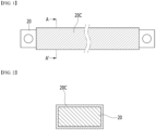
- a conventional busbar 20 is a rod-shaped metal member that extends along the longitudinal direction, and a through hole for connecting with a terminal busbar of a battery module may be formed at both end parts of the busbar 20.
- a busbar 20 is configured to be in charge of HV (High voltage) connection in the battery pack.
- the HV connection means a connection that serves as a power source to supply electric power
- the busbar 20 is configured to guide electrical connection of the battery module, and generally includes a metal material having excellent electrical conductivity.
- the busbar 20 may include a copper (Cu) material.
- battery packs have been required to have equipment in which flames are not ejected to the outside of the battery pack even if a fire occurs inside the battery pack. Since the flame generated inside the battery pack has a very high temperature of approximately 1000°C, the covering member 20C surrounding the busbar 20 may melt, so that the busbar 20 may be exposed. If the exposed busbar 20 comes into contact with another electrical component or conductive member to cause a short circuit, the internal flame may further spread, and the flame may propagate to the outside of the battery pack. This could ultimately lead to an explosion of the battery pack or the vehicle equipped with the battery pack.
- a busbar assembly comprising: a busbar for guiding electrical connection inside the battery pack; a glass fiber layer that includes glass fibers and surrounds the busbar; a fire resistant silicone layer that fills an empty space of the glass fiber layer and surrounds the busbar; and a glass fiber tape that surrounds the fire resistant silicone layer.
- the fire resistant silicone layer may be formed through injection molding of a fire resistant silicone material onto the busbar in the state of being surrounded by the glass fiber layer.
- the fire resistant silicone layer may fill a space between the woven glass fibers.
- the glass fiber tape may surround an outer peripheral surface of the fire resistant silicone layer.
- the glass fiber tape may be a rectangular tape having a long side and a short side, and the glass fiber tape may surround the fire resistant silicone layer along the long side of the glass fiber tape.
- the glass fiber tape may be wound around the fire resistant silicone layer multiple times along the longitudinal direction of the busbar so as to form overlapping layers in at least partial areas.
- the glass fiber tape may be wound obliquely multiple times around the fire resistant silicone layer so that partial areas between any one layer of the glass fiber tape and another layer adjacent thereto overlap.
- the fire resistant silicone layer may include a silicone material that is ceramified at high temperature.
- a battery pack comprising: at least one busbar assembly as described above; battery modules; a BDU (Battery Disconnect Unit) module that controls electrical connection of the battery modules; and a BMS (Battery Management System) module that monitors and controls the operation of the battery module, wherein the at least one busbar assembly electrically connects at least one of between the battery modules, between the battery module and the BDU module, between the battery module and the BMS module, or between the BDU module and the BMS module.
- BDU Battery Disconnect Unit
- BMS Battery Management System
- a fire resistant silicone layer that is ceramified at high heat or flame, a glass fiber layer that supplements the structural rigidity of the fire resistant silicone layer, and a glass fiber tape that surrounds the fire resistant silicone layer are provided in the busbar assembly, so that the electrical insulation properties of the busbar assembly can be maintained even under high heat or flame conditions.
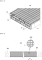
- FIG. 7 is a plan view showing a state in which a fire resistant silicone layer is provided in the busbar assembly of FIG. 6 .
- FIG. 8 is a cross-sectional view showing a cross section taken along the cutting line B-B' of FIG. 7 .
- the glass fiber layer 400 in the present disclosure is a fabric made in a shape in which glass fibers 400W are woven, the shape of the woven glass fibers or the weaving method are not particularly limited.
- the fire resistant silicone material is a material that is formed into ceramic when exposed to flame or at high heat, unlike common silicone materials that burn when exposed to flame or burn at high temperatures.
- the fire resistant silicone material may be a silicone material that is ceramified when the temperature exceeds a certain temperature.
- the fire resistant silicone material may include silicone polymer and silica.
- the applied silicone polymer may be a polysiloxane-based compound having a vinyl group as a functional group, and corresponds to a base material for a fire resistant silicone material.
- the silica may be fumed silica, which is a reinforcing filler included in the silicone polymer.
- a high-purity silicone chloride (SiCl 4 ) compound can be produced using metallic silicone as a main raw material through reaction with hydrochloric acid and purification process, and this can be reacted with hydrogen and oxygen in a high temperature flame to obtain fumed silica.
- the fire resistant silicone may contain platinum Pt as a catalyst.
- the fire resistant silicone layer 300 does not burn or melt, but can be ceramified and maintain electrical insulation properties, even if exposed to flame or placed in a high-temperature environment.
- a space S may be formed between the intersecting glass fiber strands 400S in the glass fiber layer 400, which is a fabric, and a predetermined space may also be formed between the glass fiber layer 400 and the busbar 200. Further, spaces may be formed between the glass fibers 400W which are twisted and entangled within the glass fiber strands 400S themselves. During the process of injection molding the fire resistant silicone layer 300, the fire resistant silicone material may permeate into these spaces. The fire resistant silicone layer 300 can fill the space between the woven glass fibers 400W.
- the fire resistant silicone layer 300 When the fire resistant silicone layer 300 is ceramified in a flame or high-temperature environment, the electrical insulation properties of the fire resistant silicone layer 300 can be maintained, but the strength of the fire resistant silicone layer 300 becomes weaker, and it is more likely to be cracked due to external force.
- it has been designed such that the fire resistant silicone layer 300 fills the space between the woven glass fibers 400W, and the glass fiber layer 400 is located inside the fire resistant silicone layer 300. Thereby, it is possible to supplement the structural rigidity of the fire resistant silicone layer 300, and even if the fire resistant silicone layer 300 is ceramified, it is attempted to be prevented from being cracked by external force.
- the fire resistant silicone material permeates in the space between the glass fiber strands 400S within the glass fiber layer 400 , which is a fabric, or between the glass fibers 400W that are twisted inside the glass fiber strand 400S itself, thereby capable of realizing enhanced rigidity of the fire resistant silicone layer 300 and strong bonding strength between the fire resistant silicone layer 300 and the glass fiber layer 400.
- the busbar assembly 100 according to the present embodiment has improved fire resistance, and can maintain electrical insulation properties even in a flame or high-temperature environment.
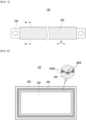
- FIG. 9 is a plan view showing a state in which a glass fiber tape is wound in the busbar assembly of FIG. 7
- the busbar assembly 100 further includes a glass fiber tape 500 surrounding the fire resistant silicone layer 300.
- the glass fiber tape may surround the outer peripheral surface of the fire resistant silicone layer 300.
- the glass fiber tape 500 may include a glass fiber substrate layer and an adhesive layer formed on one surface of the glass fiber substrate layer.
- the glass fiber substrate layer may be a woven fabric containing glass fibers, and the adhesive layer may include at least one of acrylic resin or silicone resin.
- the glass fiber tape 500 may be a rectangular tape having a long side 500L and a short side 500S. That is, the long side 500L herein refers to a relatively long side of the rectangular tape, and the short side 500S refers to a relatively short side of the rectangular tape.
- Such a glass fiber tape 500 can surround the fire resistant silicone layer 300 along the long side 500L of the glass fiber tape 500.
- the glass fiber tape 500 may be wound multiple times around the fire resistant silicone layer 300 along the longitudinal direction Ld of the busbar 200 so as to form overlapping layers 510 and 520 in at least partial areas.
- the layers 510 and 520 of the glass fiber tape 500 correspond to an interlayer structure formed by overlapping at least partial areas among the portions of the glass fiber tape 500 adjacent to each other.
- the glass fiber tape 500 may be wound obliquely multiple times around the fire resistant silicone layer 300 so that partial areas between any one layer 510 of the glass fiber tape 500 and another layer 520 adjacent thereto overlap.
- partial areas of both end parts of the fire resistant silicone layer 300 are expressed as exposed without being wound around the glass fiber tape 500, however, this is for convenience of explanation, and the entire area of the fire resistant silicone layer 300 may be wrapped by the glass fiber tape 500.
- the glass fiber tape 500 can protect the glass fiber layer 400 and the fire resistant silicone layer 300 from flame. That is, the glass fiber tape 500 completely surrounds the fire resistant silicone layer 300 and can temporarily protect the glass fiber layer 400 and the fire resistant silicone layer 300 from flames generated inside the battery pack.
- the one or more battery modules according to embodiments of the present disclosure described above can be mounted together with various control and protection systems such as a BMS (battery management system), a BDU(battery disconnect unit), and a cooling system to form a battery pack.
- BMS battery management system
- BDU battery disconnect unit
- the battery module or the battery pack can be applied to various devices. Specifically, it can be applied to vehicle means such as an electric bike, an electric vehicle, and a hybrid electric vehicle, or an ESS (Energy Storage System) and may be applied to various devices capable of using a secondary battery, without being limited thereto.
- vehicle means such as an electric bike, an electric vehicle, and a hybrid electric vehicle, or an ESS (Energy Storage System) and may be applied to various devices capable of using a secondary battery, without being limited thereto.
- ESS Electronicgy Storage System
Landscapes
- Chemical & Material Sciences (AREA)
- Chemical Kinetics & Catalysis (AREA)
- Electrochemistry (AREA)
- General Chemical & Material Sciences (AREA)
- Engineering & Computer Science (AREA)
- Manufacturing & Machinery (AREA)
- Inorganic Chemistry (AREA)
- Health & Medical Sciences (AREA)
- Medicinal Chemistry (AREA)
- Polymers & Plastics (AREA)
- Organic Chemistry (AREA)
- Microelectronics & Electronic Packaging (AREA)
- Battery Mounting, Suspending (AREA)
- Connection Of Batteries Or Terminals (AREA)
- Insulated Conductors (AREA)
Applications Claiming Priority (2)
| Application Number | Priority Date | Filing Date | Title |
|---|---|---|---|
| KR1020230011439A KR20240119411A (ko) | 2023-01-30 | 2023-01-30 | 버스바 조립체 및 이를 포함하는 전지팩 |
| PCT/KR2023/021858 WO2024162624A1 (ko) | 2023-01-30 | 2023-12-28 | 버스바 조립체 및 이를 포함하는 전지팩 |
Publications (2)
| Publication Number | Publication Date |
|---|---|
| EP4535547A1 true EP4535547A1 (de) | 2025-04-09 |
| EP4535547A4 EP4535547A4 (de) | 2025-12-03 |
Family
ID=92146978
Family Applications (1)
| Application Number | Title | Priority Date | Filing Date |
|---|---|---|---|
| EP23920173.4A Pending EP4535547A4 (de) | 2023-01-30 | 2023-12-28 | Sammelschienenanordnung und batteriepack damit |
Country Status (6)
| Country | Link |
|---|---|
| US (1) | US20260024883A1 (de) |
| EP (1) | EP4535547A4 (de) |
| JP (1) | JP2025524436A (de) |
| KR (1) | KR20240119411A (de) |
| CN (1) | CN119585941A (de) |
| WO (1) | WO2024162624A1 (de) |
Families Citing this family (1)
| Publication number | Priority date | Publication date | Assignee | Title |
|---|---|---|---|---|
| KR20240119410A (ko) * | 2023-01-30 | 2024-08-06 | 주식회사 엘지에너지솔루션 | 버스바 조립체 및 이를 포함하는 전지팩 |
Family Cites Families (11)
| Publication number | Priority date | Publication date | Assignee | Title |
|---|---|---|---|---|
| JP6466252B2 (ja) | 2014-06-19 | 2019-02-06 | 株式会社ジェイデバイス | 半導体パッケージ及びその製造方法 |
| KR20160041311A (ko) * | 2014-10-07 | 2016-04-18 | 주식회사 엘지화학 | 내화성 안전 부재를 포함하는 전지팩 |
| KR20160049260A (ko) * | 2014-10-27 | 2016-05-09 | 엘에스전선 주식회사 | 플렉서블 버스바 |
| KR102926964B1 (ko) * | 2020-05-15 | 2026-02-11 | 주식회사 엘지에너지솔루션 | 화재 안전성이 우수한 버스바 |
| CN214624512U (zh) * | 2021-05-13 | 2021-11-05 | 深圳市富程威科技有限公司 | 一种绕包带、高压连接件和动力电池 |
| CN215770643U (zh) * | 2021-06-23 | 2022-02-08 | 深圳市沃尔热缩有限公司 | 母排连接件 |
| US12503797B2 (en) * | 2021-07-13 | 2025-12-23 | Systems Protection Group Us Llc | Circumferentially continuous, fire suppressing, dielectric sleeve |
| CN217405140U (zh) * | 2022-05-06 | 2022-09-09 | 德塔云母材料科技(上海)有限公司 | 一种模压电动汽车母排绝缘件 |
| CN218274013U (zh) * | 2022-06-28 | 2023-01-10 | 广东合晟新能源科技有限公司 | 防火挤塑折弯母排 |
| CN115458871B (zh) * | 2022-10-12 | 2025-04-18 | 东莞市朗晟材料科技有限公司 | 一种新型防火耐高温绝缘的电池高压连接件及制作工艺 |
| KR20240119410A (ko) * | 2023-01-30 | 2024-08-06 | 주식회사 엘지에너지솔루션 | 버스바 조립체 및 이를 포함하는 전지팩 |
-
2023
- 2023-01-30 KR KR1020230011439A patent/KR20240119411A/ko active Pending
- 2023-12-28 CN CN202380053445.3A patent/CN119585941A/zh active Pending
- 2023-12-28 WO PCT/KR2023/021858 patent/WO2024162624A1/ko not_active Ceased
- 2023-12-28 JP JP2024574794A patent/JP2025524436A/ja active Pending
- 2023-12-28 EP EP23920173.4A patent/EP4535547A4/de active Pending
- 2023-12-28 US US18/994,578 patent/US20260024883A1/en active Pending
Also Published As
| Publication number | Publication date |
|---|---|
| CN119585941A (zh) | 2025-03-07 |
| US20260024883A1 (en) | 2026-01-22 |
| EP4535547A4 (de) | 2025-12-03 |
| KR20240119411A (ko) | 2024-08-06 |
| JP2025524436A (ja) | 2025-07-30 |
| WO2024162624A1 (ko) | 2024-08-08 |
Similar Documents
| Publication | Publication Date | Title |
|---|---|---|
| EP4531192A1 (de) | Sammelschienenanordnung und batteriepack damit | |
| EP4535547A1 (de) | Sammelschienenanordnung und batteriepack damit | |
| EP4535546A1 (de) | Sammelschienenanordnung und batteriepack damit | |
| EP4531193A1 (de) | Sammelschienenanordnung und batteriepack damit | |
| EP4597733A1 (de) | Sammelschienenanordnung und batteriepack damit | |
| EP4564581A1 (de) | Sammelschienenanordnung und batteriepack damit | |
| EP4531196A1 (de) | Sammelschienenanordnung und batteriepack damit | |
| EP4485671A1 (de) | Sammelschienenanordnung und batteriepack damit | |
| EP4597734A1 (de) | Sammelschienenanordnung und batteriepack damit | |
| EP4661202A1 (de) | Sammelschienenanordnung und batteriepack damit | |
| EP4604303A1 (de) | Sammelschienenanordnung und batteriepack damit | |
| EP4614700A1 (de) | Sammelschienenanordnung und batteriepack damit | |
| KR20240119414A (ko) | 버스바 조립체 및 이를 포함하는 전지팩 | |
| KR20250014833A (ko) | 버스바 조립체 및 이를 포함하는 전지 팩 | |
| KR20250164905A (ko) | 버스바 조립체 및 이를 포함하는 전지 팩 | |
| KR20260047861A (ko) | 버스바 조립체 및 이를 포함하는 전지 팩 | |
| KR20250058590A (ko) | 버스바 조립체 및 이를 포함하는 전지 팩 | |
| KR20240175641A (ko) | 버스바 조립체 및 이를 포함하는 전지 팩 | |
| KR20250059891A (ko) | 버스바 조립체 및 이를 포함하는 전지팩 | |
| KR20250030682A (ko) | 버스바 조립체 및 이를 포함하는 전지 팩 |
Legal Events
| Date | Code | Title | Description |
|---|---|---|---|
| STAA | Information on the status of an ep patent application or granted ep patent |
Free format text: STATUS: THE INTERNATIONAL PUBLICATION HAS BEEN MADE |
|
| PUAI | Public reference made under article 153(3) epc to a published international application that has entered the european phase |
Free format text: ORIGINAL CODE: 0009012 |
|
| STAA | Information on the status of an ep patent application or granted ep patent |
Free format text: STATUS: REQUEST FOR EXAMINATION WAS MADE |
|
| 17P | Request for examination filed |
Effective date: 20241231 |
|
| AK | Designated contracting states |
Kind code of ref document: A1 Designated state(s): AL AT BE BG CH CY CZ DE DK EE ES FI FR GB GR HR HU IE IS IT LI LT LU LV MC ME MK MT NL NO PL PT RO RS SE SI SK SM TR |
|
| A4 | Supplementary search report drawn up and despatched |
Effective date: 20251031 |
|
| RIC1 | Information provided on ipc code assigned before grant |
Ipc: H01M 50/521 20210101AFI20251027BHEP Ipc: H01M 50/595 20210101ALI20251027BHEP Ipc: H01M 50/588 20210101ALI20251027BHEP Ipc: H01M 50/526 20210101ALI20251027BHEP Ipc: C08L 83/04 20060101ALI20251027BHEP Ipc: H01M 10/42 20060101ALI20251027BHEP Ipc: H01M 50/522 20210101ALI20251027BHEP |