EP4535577A1 - Positionierungsvorrichtung und lastwagen - Google Patents
Positionierungsvorrichtung und lastwagen Download PDFInfo
- Publication number
- EP4535577A1 EP4535577A1 EP23815222.7A EP23815222A EP4535577A1 EP 4535577 A1 EP4535577 A1 EP 4535577A1 EP 23815222 A EP23815222 A EP 23815222A EP 4535577 A1 EP4535577 A1 EP 4535577A1
- Authority
- EP
- European Patent Office
- Prior art keywords
- location
- pin
- location pin
- mounting base
- elastic sleeve
- Prior art date
- Legal status (The legal status is an assumption and is not a legal conclusion. Google has not performed a legal analysis and makes no representation as to the accuracy of the status listed.)
- Pending
Links
Images


Classifications
-
- B—PERFORMING OPERATIONS; TRANSPORTING
- B60—VEHICLES IN GENERAL
- B60K—ARRANGEMENT OR MOUNTING OF PROPULSION UNITS OR OF TRANSMISSIONS IN VEHICLES; ARRANGEMENT OR MOUNTING OF PLURAL DIVERSE PRIME-MOVERS IN VEHICLES; AUXILIARY DRIVES FOR VEHICLES; INSTRUMENTATION OR DASHBOARDS FOR VEHICLES; ARRANGEMENTS IN CONNECTION WITH COOLING, AIR INTAKE, GAS EXHAUST OR FUEL SUPPLY OF PROPULSION UNITS IN VEHICLES
- B60K1/00—Arrangement or mounting of electrical propulsion units
- B60K1/04—Arrangement or mounting of electrical propulsion units of the electric storage means for propulsion
-
- B—PERFORMING OPERATIONS; TRANSPORTING
- B60—VEHICLES IN GENERAL
- B60L—PROPULSION OF ELECTRICALLY-PROPELLED VEHICLES; SUPPLYING ELECTRIC POWER FOR AUXILIARY EQUIPMENT OF ELECTRICALLY-PROPELLED VEHICLES; ELECTRODYNAMIC BRAKE SYSTEMS FOR VEHICLES IN GENERAL; MAGNETIC SUSPENSION OR LEVITATION FOR VEHICLES; MONITORING OPERATING VARIABLES OF ELECTRICALLY-PROPELLED VEHICLES; ELECTRIC SAFETY DEVICES FOR ELECTRICALLY-PROPELLED VEHICLES
- B60L53/00—Methods of charging batteries, specially adapted for electric vehicles; Charging stations or on-board charging equipment therefor; Exchange of energy storage elements in electric vehicles
- B60L53/80—Exchanging energy storage elements, e.g. removable batteries
-
- B—PERFORMING OPERATIONS; TRANSPORTING
- B60—VEHICLES IN GENERAL
- B60L—PROPULSION OF ELECTRICALLY-PROPELLED VEHICLES; SUPPLYING ELECTRIC POWER FOR AUXILIARY EQUIPMENT OF ELECTRICALLY-PROPELLED VEHICLES; ELECTRODYNAMIC BRAKE SYSTEMS FOR VEHICLES IN GENERAL; MAGNETIC SUSPENSION OR LEVITATION FOR VEHICLES; MONITORING OPERATING VARIABLES OF ELECTRICALLY-PROPELLED VEHICLES; ELECTRIC SAFETY DEVICES FOR ELECTRICALLY-PROPELLED VEHICLES
- B60L50/00—Electric propulsion with power supplied within the vehicle
- B60L50/50—Electric propulsion with power supplied within the vehicle using propulsion power supplied by batteries or fuel cells
- B60L50/60—Electric propulsion with power supplied within the vehicle using propulsion power supplied by batteries or fuel cells using power supplied by batteries
- B60L50/64—Constructional details of batteries specially adapted for electric vehicles
-
- B—PERFORMING OPERATIONS; TRANSPORTING
- B60—VEHICLES IN GENERAL
- B60S—SERVICING, CLEANING, REPAIRING, SUPPORTING, LIFTING, OR MANOEUVRING OF VEHICLES, NOT OTHERWISE PROVIDED FOR
- B60S5/00—Servicing, maintaining, repairing, or refitting of vehicles
- B60S5/06—Supplying batteries to, or removing batteries from, vehicles
-
- H—ELECTRICITY
- H01—ELECTRIC ELEMENTS
- H01M—PROCESSES OR MEANS, e.g. BATTERIES, FOR THE DIRECT CONVERSION OF CHEMICAL ENERGY INTO ELECTRICAL ENERGY
- H01M50/00—Constructional details or processes of manufacture of the non-active parts of electrochemical cells other than fuel cells, e.g. hybrid cells
- H01M50/20—Mountings; Secondary casings or frames; Racks, modules or packs; Suspension devices; Shock absorbers; Transport or carrying devices; Holders
- H01M50/233—Mountings; Secondary casings or frames; Racks, modules or packs; Suspension devices; Shock absorbers; Transport or carrying devices; Holders characterised by physical properties of casings or racks, e.g. dimensions
- H01M50/242—Mountings; Secondary casings or frames; Racks, modules or packs; Suspension devices; Shock absorbers; Transport or carrying devices; Holders characterised by physical properties of casings or racks, e.g. dimensions adapted for protecting batteries against vibrations, collision impact or swelling
-
- H—ELECTRICITY
- H01—ELECTRIC ELEMENTS
- H01M—PROCESSES OR MEANS, e.g. BATTERIES, FOR THE DIRECT CONVERSION OF CHEMICAL ENERGY INTO ELECTRICAL ENERGY
- H01M50/00—Constructional details or processes of manufacture of the non-active parts of electrochemical cells other than fuel cells, e.g. hybrid cells
- H01M50/20—Mountings; Secondary casings or frames; Racks, modules or packs; Suspension devices; Shock absorbers; Transport or carrying devices; Holders
- H01M50/249—Mountings; Secondary casings or frames; Racks, modules or packs; Suspension devices; Shock absorbers; Transport or carrying devices; Holders specially adapted for aircraft or vehicles, e.g. cars or trains
-
- B—PERFORMING OPERATIONS; TRANSPORTING
- B60—VEHICLES IN GENERAL
- B60K—ARRANGEMENT OR MOUNTING OF PROPULSION UNITS OR OF TRANSMISSIONS IN VEHICLES; ARRANGEMENT OR MOUNTING OF PLURAL DIVERSE PRIME-MOVERS IN VEHICLES; AUXILIARY DRIVES FOR VEHICLES; INSTRUMENTATION OR DASHBOARDS FOR VEHICLES; ARRANGEMENTS IN CONNECTION WITH COOLING, AIR INTAKE, GAS EXHAUST OR FUEL SUPPLY OF PROPULSION UNITS IN VEHICLES
- B60K1/00—Arrangement or mounting of electrical propulsion units
- B60K1/04—Arrangement or mounting of electrical propulsion units of the electric storage means for propulsion
- B60K2001/0455—Removal or replacement of the energy storages
- B60K2001/0488—Removal or replacement of the energy storages with arrangements for pivoting
-
- B—PERFORMING OPERATIONS; TRANSPORTING
- B60—VEHICLES IN GENERAL
- B60K—ARRANGEMENT OR MOUNTING OF PROPULSION UNITS OR OF TRANSMISSIONS IN VEHICLES; ARRANGEMENT OR MOUNTING OF PLURAL DIVERSE PRIME-MOVERS IN VEHICLES; AUXILIARY DRIVES FOR VEHICLES; INSTRUMENTATION OR DASHBOARDS FOR VEHICLES; ARRANGEMENTS IN CONNECTION WITH COOLING, AIR INTAKE, GAS EXHAUST OR FUEL SUPPLY OF PROPULSION UNITS IN VEHICLES
- B60K1/00—Arrangement or mounting of electrical propulsion units
- B60K1/04—Arrangement or mounting of electrical propulsion units of the electric storage means for propulsion
- B60K2001/0455—Removal or replacement of the energy storages
- B60K2001/0494—Removal or replacement of the energy storages with arrangements for sliding
-
- B—PERFORMING OPERATIONS; TRANSPORTING
- B60—VEHICLES IN GENERAL
- B60L—PROPULSION OF ELECTRICALLY-PROPELLED VEHICLES; SUPPLYING ELECTRIC POWER FOR AUXILIARY EQUIPMENT OF ELECTRICALLY-PROPELLED VEHICLES; ELECTRODYNAMIC BRAKE SYSTEMS FOR VEHICLES IN GENERAL; MAGNETIC SUSPENSION OR LEVITATION FOR VEHICLES; MONITORING OPERATING VARIABLES OF ELECTRICALLY-PROPELLED VEHICLES; ELECTRIC SAFETY DEVICES FOR ELECTRICALLY-PROPELLED VEHICLES
- B60L2200/00—Type of vehicles
- B60L2200/36—Vehicles designed to transport cargo, e.g. trucks
-
- B—PERFORMING OPERATIONS; TRANSPORTING
- B60—VEHICLES IN GENERAL
- B60Y—INDEXING SCHEME RELATING TO ASPECTS CROSS-CUTTING VEHICLE TECHNOLOGY
- B60Y2200/00—Type of vehicle
- B60Y2200/10—Road Vehicles
- B60Y2200/14—Trucks; Load vehicles, Busses
-
- H—ELECTRICITY
- H01—ELECTRIC ELEMENTS
- H01M—PROCESSES OR MEANS, e.g. BATTERIES, FOR THE DIRECT CONVERSION OF CHEMICAL ENERGY INTO ELECTRICAL ENERGY
- H01M2220/00—Batteries for particular applications
- H01M2220/20—Batteries in motive systems, e.g. vehicle, ship, plane
-
- H—ELECTRICITY
- H01—ELECTRIC ELEMENTS
- H01R—ELECTRICALLY-CONDUCTIVE CONNECTIONS; STRUCTURAL ASSOCIATIONS OF A PLURALITY OF MUTUALLY-INSULATED ELECTRICAL CONNECTING ELEMENTS; COUPLING DEVICES; CURRENT COLLECTORS
- H01R13/00—Details of coupling devices of the kinds covered by groups H01R12/70 or H01R24/00 - H01R33/00
- H01R13/62—Means for facilitating engagement or disengagement of coupling parts or for holding them in engagement
- H01R13/629—Additional means for facilitating engagement or disengagement of coupling parts, e.g. aligning or guiding means, levers, gas pressure electrical locking indicators, manufacturing tolerances
- H01R13/631—Additional means for facilitating engagement or disengagement of coupling parts, e.g. aligning or guiding means, levers, gas pressure electrical locking indicators, manufacturing tolerances for engagement only
-
- Y—GENERAL TAGGING OF NEW TECHNOLOGICAL DEVELOPMENTS; GENERAL TAGGING OF CROSS-SECTIONAL TECHNOLOGIES SPANNING OVER SEVERAL SECTIONS OF THE IPC; TECHNICAL SUBJECTS COVERED BY FORMER USPC CROSS-REFERENCE ART COLLECTIONS [XRACs] AND DIGESTS
- Y02—TECHNOLOGIES OR APPLICATIONS FOR MITIGATION OR ADAPTATION AGAINST CLIMATE CHANGE
- Y02T—CLIMATE CHANGE MITIGATION TECHNOLOGIES RELATED TO TRANSPORTATION
- Y02T10/00—Road transport of goods or passengers
- Y02T10/60—Other road transportation technologies with climate change mitigation effect
- Y02T10/70—Energy storage systems for electromobility, e.g. batteries
-
- Y—GENERAL TAGGING OF NEW TECHNOLOGICAL DEVELOPMENTS; GENERAL TAGGING OF CROSS-SECTIONAL TECHNOLOGIES SPANNING OVER SEVERAL SECTIONS OF THE IPC; TECHNICAL SUBJECTS COVERED BY FORMER USPC CROSS-REFERENCE ART COLLECTIONS [XRACs] AND DIGESTS
- Y02—TECHNOLOGIES OR APPLICATIONS FOR MITIGATION OR ADAPTATION AGAINST CLIMATE CHANGE
- Y02T—CLIMATE CHANGE MITIGATION TECHNOLOGIES RELATED TO TRANSPORTATION
- Y02T10/00—Road transport of goods or passengers
- Y02T10/60—Other road transportation technologies with climate change mitigation effect
- Y02T10/7072—Electromobility specific charging systems or methods for batteries, ultracapacitors, supercapacitors or double-layer capacitors
Definitions
- a battery swap frame into which numerous battery packs are integrated cooperates with a vehicle-mounted battery swap base in a mechanical and electrical manner, and a battery system is quickly swapped by upwards hoisting or laterally forking the battery swap frame.
- the buffer assembly further includes an inner metal sleeve and an outer metal sleeve, the inner metal sleeve is disposed between the second elastic sleeve and the location pin, and the outer metal sleeve is disposed between the second elastic sleeve and the location pin mounting base.
- the buffer assembly includes a third elastic sleeve
- the location pin includes a pin core and a pin shell
- the third elastic sleeve is connected with the pin core and the pin shell respectively
- the third elastic sleeve is located between the pin core and the pin shell.
- the truck further includes a socket of a battery swap connector and a plug of the battery swap connector, where the socket of the battery swap connector is disposed on a battery frame of the truck, the plug of the battery swap connector is disposed on a battery swap base of the truck, and the plug of the battery swap connector is inserted into the socket of the battery swap connector.
- the plurality of the positioning devices are disposed at intervals in a length direction of a battery frame of the truck.
- a positioning device configured to locate a relative location between a battery frame and a battery swap base of a heavy-duty battery swap system of a truck.
- the positioning device includes: a location pin, where the location pin is disposed on a location pin mounting base of the battery swap base; a location hole, where the location hole is disposed on a location hole mounting base of the battery frame, and the location pin is inserted into the location hole; and a buffer assembly, where the buffer assembly is disposed between the location pin mounting base and the location pin and/or between the location pin and the location hole mounting base and/or on the location pin, such that in a case that a location deviation occurs in a radial direction of the location pin and between the battery frame and the battery swap base, the buffer assembly is pressed to offset the location deviation, and in a case that a relative movement occurs between the battery frame and the battery swap base, the buffer assembly provides a buffer for shock absorption in the radial direction of the location pin.
- orientation or positional relationships indicated by the terms “above”, “below”, “right”, etc. are based on the orientation or positional relationship shown in the accompanying drawings and are merely for facilitating the description and simplifying the description, rather than indicating or implying that a device or element referred to must have a particular orientation or be constructed and operated in a particular orientation, and cannot be interpreted as limiting the present disclosure accordingly.
- the terms “first” and “second” are merely used for distinguishing in description and have no special meanings.
- the present disclosure provides a positioning device configured to locate a relative location between a battery frame 1 and a battery swap base 2 of a heavy-duty battery swap system of a truck. That is, the truck includes the heavy-duty battery swap system, the heavy-duty battery swap system includes the battery frame 1 and the battery swap base 2, and the load device is configured to locate the relative location between the battery frame 1 and the battery swap base 2.
- an outer wall of the first elastic sleeve 51 is configured with a first recess, and the inner wall of the location hole 3 is embedded in the first recess. That is, the location hole mounting base is embedded in the first recess.
- the first elastic sleeve 51 is located between the location pin 4 and the location hole mounting base.
- the inner wall of the location hole 3 is embedded in the first recess of the first elastic sleeve 51, that is, the location hole mounting base is embedded in the first recess, so as to fix the first elastic sleeve 51 to the location hole mounting base of the battery frame 1.
- the first elastic sleeve 51 is mounted or dismounted advantageously.
- the location pin 4 is fixedly disposed on the location pin mounting base, and the location pin 4 is rigidly and fixedly connected with the location pin mounting base.
- the location pin 4 is configured with a first portion 41 and a second portion 42.
- the first portion 41 is conical
- the second portion 42 is cylindrical
- the second portion 42 is disposed closer to the location pin mounting base compared with the first portion 41.
- an inner wall of the first elastic sleeve 51 is configured with a first metal sleeve (not shown in the figure), and a second metal sleeve (not shown in the figure) is configured between the inner wall of the location hole 3 and the first elastic sleeve 51.
- the first metal sleeve is in direct contact with the second portion 42, so as to prolong a service life of the first elastic sleeve 51.
- the second elastic sleeve 52 is composed of a plurality of rubber sheets or a plurality of springs. It can be understood that the second elastic sleeve 52 can alternatively be made of other elastic materials.
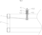
- the positioning device further includes a nut 7.
- the location pin 4 is configured with an external thread.
- the nut 7 is in threaded connection with the external thread, and the location pin 4 is configured with a limit surface 43.
- the limit surface 43 and the nut 7 abut against two ends, in an axial direction of the location pin 4, of the second elastic sleeve 52 respectively.
- the location pin 4 penetrates the second elastic sleeve 52, and the limit surface 43 of the location pin 4 abuts against an upper end surface, in the axial direction of the location pin 4, of the second elastic sleeve 52.
- the first portion 41 and the second portion 42 are integrally formed.
- the conical first portion 41 can guide insertion of the location pin 4 into the location hole 3, such that the location pin 4 is inserted into the location hole 3 advantageously.
- the second portion 42 is cylindrical. After the location pin 4 is inserted into the location hole 3, the second portion 42 of the location pin 4 cooperates with the location hole 3 in locating the battery frame 1 and the battery swap base 2. In this Example 2, the second portion 42 is in rigid contact with an inner wall of the location hole 3.
- a buffer assembly of this example further includes an inner metal sleeve 54 and an outer metal sleeve 55, and the other structures are the same.
- a positioning device includes a location pin 4 disposed on a location pin mounting base of a battery swap base 2, a location hole 3 disposed on a location hole mounting base of a battery frame 1, and a buffer assembly.
- the location pin 4 is inserted into the location hole 3.
- the buffer assembly is disposed between the location pin mounting base and the location pin 4 and/or between the location pin 4 and the location hole mounting base and/or on the location pin 4.
- the buffer assembly can absorb a hole spacing deviation in a case that the hole spacing deviation exists between the battery frame 1 and the battery swap base 2, and in a case that a relative movement exists between the battery frame 1 and the battery swap base 2, the buffer assembly can provide a buffer for shock absorption in a radial direction of the location pin 4.
- the third elastic sleeve 53 can be made of a plurality of rubber sheets; alternatively, the third elastic sleeve 53 is a structure similar to a particle damper, that is, a particle substance is filled between the pin core 401 and the pin shell 402 to implement the buffer for the shock absorption role of a location pin hole structure. It can be understood that the pin shell 402 is configured with a first portion 41 and a second portion 42, the first portion 41 is conical, and the second portion 42 is cylindrical.
- the location pin 4 is fixedly disposed on the location pin mounting base, and the location pin 4 is rigidly and fixedly connected with the location pin mounting base.
- a positioning device includes a location pin 4 disposed on a location pin mounting base of a battery swap base 2, a location hole 3 disposed on a location hole mounting base of a battery frame 1, and a buffer assembly.
- the location pin 4 is inserted into the location hole 3.
- the buffer assembly is disposed between the location pin mounting base and the location pin 4 and/or between the location pin 4 and the location hole mounting base and/or on the location pin 4.
- the buffer assembly can absorb a hole spacing deviation in a case that the hole spacing deviation exists between the battery frame 1 and the battery swap base 2, and in a case that a relative movement exists between the battery frame 1 and the battery swap base 2, the buffer assembly can provide a buffer for shock absorption in a radial direction of the location pin 4.
- the buffer assembly further includes the inner metal sleeve 54 and the outer metal sleeve 55, the inner metal sleeve 54 is disposed between a second elastic sleeve 52 and a location pin 4, and the outer metal sleeve 55 is disposed between the second elastic sleeve 52 and a location pin mounting base.
- the inner metal sleeve 54 and the outer metal sleeve 55 can bear high-strength friction and have high wear resistance.
- the second elastic sleeve 52 can be protected and a service life of the second elastic sleeve 52 can be prolonged.
- a positioning device includes a location pin 4 disposed on a location pin mounting base of a battery swap base 2, a location hole 3 disposed on a location hole mounting base of a battery frame 1, and a buffer assembly.
- the location pin 4 is inserted into the location hole 3.
- the buffer assembly is disposed between the location pin mounting base and the location pin 4 and/or between the location pin 4 and the location hole mounting base and/or on the location pin 4.
- the buffer assembly can absorb a hole spacing deviation in a case that the hole spacing deviation exists between the battery frame 1 and the battery swap base 2, and in a case that a relative movement exists between the battery frame 1 and the battery swap base 2, the buffer assembly can provide a buffer for shock absorption in a radial direction of the location pin 4.
- the location pin 4 includes a pin core 401 and a pin shell 402, and the pin shell 402 sleeves the pin core 401.
- the location pin 4 is fixedly disposed on the location pin mounting base, and the location pin 4 is rigidly and fixedly connected with the location pin mounting base.
Landscapes
- Engineering & Computer Science (AREA)
- Mechanical Engineering (AREA)
- Transportation (AREA)
- Chemical & Material Sciences (AREA)
- Power Engineering (AREA)
- General Chemical & Material Sciences (AREA)
- Chemical Kinetics & Catalysis (AREA)
- Electrochemistry (AREA)
- Aviation & Aerospace Engineering (AREA)
- Sustainable Energy (AREA)
- Sustainable Development (AREA)
- Life Sciences & Earth Sciences (AREA)
- Combustion & Propulsion (AREA)
- Insertion Pins And Rivets (AREA)
- Battery Mounting, Suspending (AREA)
- Arrangement Or Mounting Of Propulsion Units For Vehicles (AREA)
Applications Claiming Priority (2)
| Application Number | Priority Date | Filing Date | Title |
|---|---|---|---|
| CN202221333611.4U CN217468978U (zh) | 2022-05-30 | 2022-05-30 | 一种定位装置及重型电动卡车 |
| PCT/CN2023/097210 WO2023232044A1 (zh) | 2022-05-30 | 2023-05-30 | 定位装置及卡车 |
Publications (2)
| Publication Number | Publication Date |
|---|---|
| EP4535577A1 true EP4535577A1 (de) | 2025-04-09 |
| EP4535577A4 EP4535577A4 (de) | 2025-10-01 |
Family
ID=83278067
Family Applications (1)
| Application Number | Title | Priority Date | Filing Date |
|---|---|---|---|
| EP23815222.7A Pending EP4535577A4 (de) | 2022-05-30 | 2023-05-30 | Positionierungsvorrichtung und lastwagen |
Country Status (5)
| Country | Link |
|---|---|
| US (1) | US20250326324A1 (de) |
| EP (1) | EP4535577A4 (de) |
| JP (1) | JP3251467U (de) |
| CN (1) | CN217468978U (de) |
| WO (1) | WO2023232044A1 (de) |
Cited By (1)
| Publication number | Priority date | Publication date | Assignee | Title |
|---|---|---|---|---|
| KR102899158B1 (ko) * | 2025-02-28 | 2025-12-15 | 삼성이앤에이 주식회사 | 엘리베이터 모듈 구조체 및 이에 설치되는 대칭형 트랙션 구조체 |
Families Citing this family (4)
| Publication number | Priority date | Publication date | Assignee | Title |
|---|---|---|---|---|
| CN217468978U (zh) * | 2022-05-30 | 2022-09-20 | 四川智锂智慧能源科技有限公司 | 一种定位装置及重型电动卡车 |
| CN114927900B (zh) * | 2022-05-30 | 2025-09-16 | 四川智锂智慧能源科技有限公司 | 一种定位装置及重型电动卡车 |
| JP7647778B2 (ja) * | 2023-02-02 | 2025-03-18 | いすゞ自動車株式会社 | 載置装置 |
| CN116353325A (zh) * | 2023-03-06 | 2023-06-30 | 蓝谷智慧(北京)能源科技有限公司 | 定位装置及电池包快换新能源车辆 |
Family Cites Families (7)
| Publication number | Priority date | Publication date | Assignee | Title |
|---|---|---|---|---|
| US6726396B2 (en) * | 2002-05-20 | 2004-04-27 | Benjamin Plett | Shock absorber for fifth wheel trailer hitch |
| CN207664346U (zh) * | 2017-12-12 | 2018-07-27 | 南京金龙新能源汽车研究院有限公司 | 一种快换电池的插排构件 |
| CN211764962U (zh) * | 2019-12-25 | 2020-10-27 | 上海玖行能源科技有限公司 | 具备换电和充电功能的载重卡车 |
| CN112477680B (zh) * | 2020-11-20 | 2023-06-23 | 浙江吉利控股集团有限公司 | 一种车辆换电装置、双浮动吊装换电站及换电系统 |
| CN215436075U (zh) * | 2021-03-12 | 2022-01-07 | 福士汽车零部件(济南)有限公司 | 一种用于电动汽车换电的全向误差吸收缓冲装置 |
| CN113815474B (zh) * | 2021-08-23 | 2023-10-24 | 上海启源芯动力科技有限公司 | 一种换电码头牵引车、电池交换系统及其换电方法 |
| CN217468978U (zh) * | 2022-05-30 | 2022-09-20 | 四川智锂智慧能源科技有限公司 | 一种定位装置及重型电动卡车 |
-
2022
- 2022-05-30 CN CN202221333611.4U patent/CN217468978U/zh active Active
-
2023
- 2023-05-30 WO PCT/CN2023/097210 patent/WO2023232044A1/zh not_active Ceased
- 2023-05-30 EP EP23815222.7A patent/EP4535577A4/de active Pending
- 2023-05-30 US US18/870,632 patent/US20250326324A1/en active Pending
- 2023-05-30 JP JP2024600191U patent/JP3251467U/ja active Active
Cited By (1)
| Publication number | Priority date | Publication date | Assignee | Title |
|---|---|---|---|---|
| KR102899158B1 (ko) * | 2025-02-28 | 2025-12-15 | 삼성이앤에이 주식회사 | 엘리베이터 모듈 구조체 및 이에 설치되는 대칭형 트랙션 구조체 |
Also Published As
| Publication number | Publication date |
|---|---|
| US20250326324A1 (en) | 2025-10-23 |
| JP3251467U (ja) | 2025-05-29 |
| WO2023232044A1 (zh) | 2023-12-07 |
| EP4535577A4 (de) | 2025-10-01 |
| CN217468978U (zh) | 2022-09-20 |
Similar Documents
| Publication | Publication Date | Title |
|---|---|---|
| EP4535577A1 (de) | Positionierungsvorrichtung und lastwagen | |
| CN211764962U (zh) | 具备换电和充电功能的载重卡车 | |
| CN218228706U (zh) | 具有顶杆导向的电动车辆用电池包及包含其的电动车辆 | |
| CN113043906A (zh) | 一种换电式纯电动重卡换电系统结构 | |
| CN114927900B (zh) | 一种定位装置及重型电动卡车 | |
| CN110978982A (zh) | 一种重卡换电电池箱的固定结构 | |
| CN113043905A (zh) | 一种纯电动重卡换电系统锁止机构 | |
| US20260001390A1 (en) | Vehicle body support for mounting battery pack and electric vehicle | |
| CN218661384U (zh) | 换电底托及换电车 | |
| WO2024139952A1 (zh) | 快换组件及包含其的换电车辆 | |
| CN113120085B (zh) | 具有固定式后梁的车身支架、车身支架组件及电动汽车 | |
| CN111717012B (zh) | 一种电动汽车电池固定结构及电动汽车 | |
| CN218640668U (zh) | 锁止机构及包含其的电动车辆 | |
| CN116278940B (zh) | 新能源电池换电车辆的电池固定装置及固定方法 | |
| US20250296456A1 (en) | Quick-swapping connector and vehicle having same | |
| CN215244433U (zh) | 一种换电式纯电动重卡换电系统结构 | |
| CN118144533A (zh) | 一种电池包锁止机构及电动车辆 | |
| CN119058472A (zh) | 一种换电电池及具有其的换电车辆 | |
| CN216374148U (zh) | 具有避让结构的解锁件及换电设备 | |
| CN216312210U (zh) | 一种电池连接器浮动安装结构 | |
| CN215244435U (zh) | 一种纯电动重卡换电系统锁止机构 | |
| CN113665340B (zh) | 一种锁止机构、电池箱托架及电动重卡 | |
| CN206201889U (zh) | 一种应用塑料托盘的减振器结构 | |
| CN116373932A (zh) | 旁承及具有其的轨道车辆 | |
| CN211390970U (zh) | 固定装置、新能源汽车电池 |
Legal Events
| Date | Code | Title | Description |
|---|---|---|---|
| STAA | Information on the status of an ep patent application or granted ep patent |
Free format text: STATUS: THE INTERNATIONAL PUBLICATION HAS BEEN MADE |
|
| PUAI | Public reference made under article 153(3) epc to a published international application that has entered the european phase |
Free format text: ORIGINAL CODE: 0009012 |
|
| STAA | Information on the status of an ep patent application or granted ep patent |
Free format text: STATUS: REQUEST FOR EXAMINATION WAS MADE |
|
| 17P | Request for examination filed |
Effective date: 20241128 |
|
| AK | Designated contracting states |
Kind code of ref document: A1 Designated state(s): AL AT BE BG CH CY CZ DE DK EE ES FI FR GB GR HR HU IE IS IT LI LT LU LV MC ME MK MT NL NO PL PT RO RS SE SI SK SM TR |
|
| DAV | Request for validation of the european patent (deleted) | ||
| DAX | Request for extension of the european patent (deleted) | ||
| A4 | Supplementary search report drawn up and despatched |
Effective date: 20250903 |
|
| RIC1 | Information provided on ipc code assigned before grant |
Ipc: H01R 13/631 20060101AFI20250828BHEP Ipc: B60L 53/16 20190101ALI20250828BHEP Ipc: B60K 1/04 20190101ALI20250828BHEP |