EP4535614A1 - Machine à flux axial avec refroidissement direct du noyau - Google Patents
Machine à flux axial avec refroidissement direct du noyau Download PDFInfo
- Publication number
- EP4535614A1 EP4535614A1 EP23201233.6A EP23201233A EP4535614A1 EP 4535614 A1 EP4535614 A1 EP 4535614A1 EP 23201233 A EP23201233 A EP 23201233A EP 4535614 A1 EP4535614 A1 EP 4535614A1
- Authority
- EP
- European Patent Office
- Prior art keywords
- core
- stator
- sleeve
- wall
- holes
- Prior art date
- Legal status (The legal status is an assumption and is not a legal conclusion. Google has not performed a legal analysis and makes no representation as to the accuracy of the status listed.)
- Pending
Links
Images




Classifications
-
- H—ELECTRICITY
- H02—GENERATION; CONVERSION OR DISTRIBUTION OF ELECTRIC POWER
- H02K—DYNAMO-ELECTRIC MACHINES
- H02K9/00—Arrangements for cooling or ventilating
- H02K9/19—Arrangements for cooling or ventilating for machines with closed casing and closed-circuit cooling using a liquid cooling medium, e.g. oil
- H02K9/197—Arrangements for cooling or ventilating for machines with closed casing and closed-circuit cooling using a liquid cooling medium, e.g. oil in which the rotor or stator space is fluid-tight, e.g. to provide for different cooling media for rotor and stator
-
- H—ELECTRICITY
- H02—GENERATION; CONVERSION OR DISTRIBUTION OF ELECTRIC POWER
- H02K—DYNAMO-ELECTRIC MACHINES
- H02K1/00—Details of the magnetic circuit
- H02K1/06—Details of the magnetic circuit characterised by the shape, form or construction
- H02K1/12—Stationary parts of the magnetic circuit
- H02K1/14—Stator cores with salient poles
- H02K1/146—Stator cores with salient poles consisting of a generally annular yoke with salient poles
- H02K1/148—Sectional cores
-
- H—ELECTRICITY
- H02—GENERATION; CONVERSION OR DISTRIBUTION OF ELECTRIC POWER
- H02K—DYNAMO-ELECTRIC MACHINES
- H02K1/00—Details of the magnetic circuit
- H02K1/06—Details of the magnetic circuit characterised by the shape, form or construction
- H02K1/12—Stationary parts of the magnetic circuit
- H02K1/20—Stationary parts of the magnetic circuit with channels or ducts for flow of cooling medium
-
- H—ELECTRICITY
- H02—GENERATION; CONVERSION OR DISTRIBUTION OF ELECTRIC POWER
- H02K—DYNAMO-ELECTRIC MACHINES
- H02K21/00—Synchronous motors having permanent magnets; Synchronous generators having permanent magnets
- H02K21/12—Synchronous motors having permanent magnets; Synchronous generators having permanent magnets with stationary armatures and rotating magnets
- H02K21/24—Synchronous motors having permanent magnets; Synchronous generators having permanent magnets with stationary armatures and rotating magnets with magnets axially facing the armatures, e.g. hub-type cycle dynamos
-
- H—ELECTRICITY
- H02—GENERATION; CONVERSION OR DISTRIBUTION OF ELECTRIC POWER
- H02K—DYNAMO-ELECTRIC MACHINES
- H02K3/00—Details of windings
- H02K3/04—Windings characterised by the conductor shape, form or construction, e.g. with bar conductors
- H02K3/24—Windings characterised by the conductor shape, form or construction, e.g. with bar conductors with channels or ducts for cooling medium between the conductors
-
- H—ELECTRICITY
- H02—GENERATION; CONVERSION OR DISTRIBUTION OF ELECTRIC POWER
- H02K—DYNAMO-ELECTRIC MACHINES
- H02K3/00—Details of windings
- H02K3/32—Windings characterised by the shape, form or construction of the insulation
- H02K3/34—Windings characterised by the shape, form or construction of the insulation between conductors or between conductor and core, e.g. slot insulation
- H02K3/345—Windings characterised by the shape, form or construction of the insulation between conductors or between conductor and core, e.g. slot insulation between conductor and core, e.g. slot insulation
Definitions
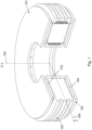
- An axial flux machine is a type of electrical machine wherein a flux is generated in axial direction, the latter being the direction of the rotational axis.
- an axial flux machine comprises a disk- or ring-shaped rotor and stator, both having a central axis corresponding to the rotational axis of the machine, the stator and rotor being axially spaced apart by a narrow air gap.
- the rotor comprises magnetic material, typically permanent magnets, generating an axial magnetic flux.
- the stator comprises a plurality of coils in which currents may run. Typically, each of the stator coils is wound around a core made of ferromagnetic material, to direct and focus the magnetic flux.
- the stator and rotor each comprise a disk- or ring-shaped component, referred to as a stator disk respectively rotor disk.
- the stator disk and rotor disk are axially spaced apart by a narrow air gap.
- the machine may comprise one rotor disk and one stator disk, one rotor disk and two stator disks, or two rotor disks and one stator disk.
- the axial flux machine may be of the torus type, having a stator yoke, or may be of the YASA type, not having a stator yoke.
- the latter machine is also referred to as, for example, a yokeless and segmented armature (YASA) motor or generator, or simply a yokeless axial flux machine.
- YASA yokeless and segmented armature
- any of the sleeve openings is provided as a perforation through the sleeve wall, i.e. a perforation being made through sleeve material.
- any of the holes, comprised in the first and second set is bordered by sleeve material over its full circumference.
- an opening is a circular hole, or an aperture having a closed circumference according to another shape.
- any of the sleeve openings is an opening extending over the full height of the sleeve, thereby splitting the respective sleeve wall in two separate portions.
- an opening is a slit in the sleeve wall, extending from the bottom side of the wall to the top side of the wall.
- the two portions of the sleeve wall, at both sides of the slit may be overlapping portions, thereby defining a zig-zag passage through the sleeve wall.
- the one or more holes comprised in the first set are provided as perforations through a sleeve wall, and the one or more holes comprised in the second set are provided as a slit in another sleeve wall, the slit extending over the full height of that other sleeve wall.
- any of the holes comprised in the first set is in fluid communication with at least one hole comprised in the second set. This implies that a fluid entering via a hole of the first set can reach some or all of the holes of the second set, and a fluid entering via a hole of the second set can reach some or all of the holes of the first set.
- both sets each comprise multiple holes, wherein any of the holes of the first set is in fluid communication with each hole of the second set.
- both sets each comprise multiple holes, wherein any of the holes of the first set is only in fluid communication with one particular hole of the second set.
- a cooling fluid supplied to the internal space of the housing will - for any of the stator members - at least partly flows via a path through the sleeve openings, thereby flowing along and/or through the respective cores.
- the first set may form the fluid entry, the fluid thus flowing from the first set towards the second set, while for another stator member, the first set may form the fluid exit, the fluid thus flowing from the second set towards the first set.
- any of the channels between the sleeve and the core is defined by:
- At least one of the channels through the core is a dedicated channel provided in a massive portion of the core.
- the channel is not provided at opposing connection surfaces, but is applied through core material.
- the channel is thus running through a solid or massive portion of the core.
- a massive portion of the core may e.g. be the core as a whole, if the cores are not provided as split core parts, or may be an individual core part forming a single piece.
- the massive portion thus refers to a single piece or solid block, although the piece or block itself may be composed of various materials, e.g. when the core is laminated.
- the channel is applied intentionally through the core material, thus being a dedicated channel. For example, it is provided as a bored channel.
- any of the channels through the core runs according to a direction perpendicular to the height direction or axial direction, and, for any of the channels through the core, the height position is such that the channel is closer to the core centre than to the first core end and is closer to the core centre than to the second core end.
- the core extends between two ends.
- the core centre is located at half height of the core, halfway between the two core ends.
- the central axis of a channel lies in a single plane at a given height position, the plane being perpendicular to the axial direction.
- each of the holes comprised in the first and/or second set defines a zig-zag passage through a sleeve wall.
- a hole in the sleeve wall is designed as a labyrinth; in a cross section according to a plane perpendicular to the axial direction, the hole is e.g. bordered by Z-shaped, S-shaped, or L-shaped edges, thereby defining respectively a Z-shaped, S-shaped or L-shaped passage through the wall. Accordingly, a fluid flowing through the hole will not just follow a single direction, but will be redirected to another direction due to the bent edges, thereby following a zig-zag trajectory.
- the core sleeve comprises a first wall directed to the outer circumferential wall of the housing, a second wall directed to the inner circumferential wall of the housing, and sidewalls directed to an adjacent stator member, the holes of the first respectively second set being provided as openings in the first respectively second wall, and
- At least some of the turns of the coil are spaced apart, thereby establishing fluid passages through the coil. This implies that spaces are available between adjacent turns of the coil, allowing the cooling fluid to flow through, thereby reaching the sleeve, after which the fluid flows through the sleeve openings acting as entry holes. Similarly, after flowing through the sleeve openings acting as exit holes, the fluid may flow through the passages between turns of the coil.
- the stator is arranged such that, for any of the stator members, a main flow of cooling fluid splits into multiple substreams, comprising:
- the above identified objectives are realized by a method for operating a stator of an axial flux machine, the method comprising:
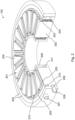
- the stator 100 further comprises guiding walls 212, wherein a guiding wall 211 is positioned between each pair of adjacent stator members 201, and extends in radial direction 106.
- the guiding walls 211 are connected at one outer end to the outer circumferential wall 205.
- the outer circumferential wall 205 comprises outer channels 209 and 210, while the space between the guiding wall outer ends and the inner circumferential wall 206 defines an inner channel 211.
- the outer and inner channels 209, 210, 211 are arranged to let a stator cooling fluid flow tangentially about the central axis.
- the guiding walls 211 are arranged to let the stator cooling fluid flow in radial direction.
- the outer channel 210 serves as a fluid supply channel or cold channel
- the outer channel 209 serves as a fluid draining channel or hot channel.
- the cooling fluid is supplied to the cold channel 210 via a supply port 207.
- apertures 400 are provided along the circumference allowing the cooling fluid to flow from the cold channel 210 to the inner space of the housing, where it flows in radial direction and is collected in the inner channel 211.
- Similar apertures are available with respect to the hot channel 209, allowing the cooling fluid to flow from the inner space of the housing to the hot channel 209.
- a drainage port 208 allows the heated cooling fluid to be drained from the hot channel 209.
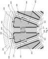
- Fig. 5 illustrates that cooling fluid reaches the sleeve 203 via fluid passages 406, the latter being present due to spacings between adjacent turns of the coil 204.
- the cooling fluid flows through the holes 305, 900 of the first set, thereby reaching the core outer surface 508.
- the first set of holes 305, 900 thus serve as entry holes.
- the fluid While flowing along the core 202, in direct contact with the core outer surfaces 508, the fluid flows in a channel 500, provided as a slit between the core outer surface 508 and the inside of the sleeve 203.
- the channel 500 extends in axial direction 105, over the full height of the sleeve 203.
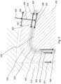
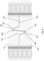
- Fig. 7 to Fig. 9 illustrate a second embodiment, wherein a portion of the cooling fluid flows through the respective cores 202. Similar to what was presented in Fig. 5 with respect to the first embodiment, in the second embodiment the main flow 405 splits into three substreams. Just like in the first embodiment, the first substream 501, 502 flows around the coil 204 and the second substream 503, 504 flows between the sleeve 203 and the coil 204. Different from the first embodiment however, in the second embodiment, the third substream flows through the core 200.
- Fig. 8 shows that the connection surfaces 801, 802 are mainly in contact with one another, but not completely, due to gaps 808, 807 remaining between the interlocking features.
- the gaps 808, 807 are provided in order to facilitate the two core halves 701, 702 to be snapped together.
- the interlocking features extend over the respective connection surfaces 801, 802, from the back side of the core part 701, 702 to the front side of the core part 701, 702. Accordingly, the gaps 808, 807 each form a channel running through the core 202, extending between the back side 906 of the core 202 and the front side 907 of the core 202, as is visible on Fig. 9 .
- the cooling fluid reaches the front side 907 of the core 202. While flowing through the channels 807, 808, the cooling fluid is in direct contact with the core material. Subsequently, the fluid flow is redirected to the axial direction 105, after which it flows through the holes 303, 304 of the second set. Fluid passages 905 between the turns of the coil 204 allow the cooling fluid to reach the inner channel 211. Thereafter, the cooling fluid flows through the second set of sleeve holes of an adjacent stator member, similar to what was presented in Fig. 4 .
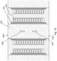
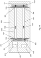
- cooling fluid may flow through the core 202, due to the presence of dedicated channels 1000, 1001 through the core 202.
- Both channels 1000, 1001 run through a massive portion of the core 202, and are applied intentionally to provide cooling channels through the core 202.
- Each channel 1000, 1001 runs in radial direction 106, and extends between the back side 1104 of the core 202 and the front side 1105 of the core.
- the channels 1000, 1001 run in a direction perpendicular to the axial direction 105, and each of them is placed at a different height position.
- a slit extending in axial direction is present between the inside of the first sleeve wall 301 and the core outer surface 1104, which may be due to a recess 312 in the first sleeve wall 301, as was illustrated in Fig. 3(b) .
Landscapes
- Engineering & Computer Science (AREA)
- Power Engineering (AREA)
- Iron Core Of Rotating Electric Machines (AREA)
Priority Applications (2)
| Application Number | Priority Date | Filing Date | Title |
|---|---|---|---|
| EP23201233.6A EP4535614A1 (fr) | 2023-10-02 | 2023-10-02 | Machine à flux axial avec refroidissement direct du noyau |
| PCT/EP2024/075947 WO2025073465A1 (fr) | 2023-10-02 | 2024-09-17 | Machine à flux axial à refroidissement direct des noyaux |
Applications Claiming Priority (1)
| Application Number | Priority Date | Filing Date | Title |
|---|---|---|---|
| EP23201233.6A EP4535614A1 (fr) | 2023-10-02 | 2023-10-02 | Machine à flux axial avec refroidissement direct du noyau |
Publications (1)
| Publication Number | Publication Date |
|---|---|
| EP4535614A1 true EP4535614A1 (fr) | 2025-04-09 |
Family
ID=88241402
Family Applications (1)
| Application Number | Title | Priority Date | Filing Date |
|---|---|---|---|
| EP23201233.6A Pending EP4535614A1 (fr) | 2023-10-02 | 2023-10-02 | Machine à flux axial avec refroidissement direct du noyau |
Country Status (2)
| Country | Link |
|---|---|
| EP (1) | EP4535614A1 (fr) |
| WO (1) | WO2025073465A1 (fr) |
Citations (7)
| Publication number | Priority date | Publication date | Assignee | Title |
|---|---|---|---|---|
| WO2010092400A2 (fr) | 2009-02-13 | 2010-08-19 | Isis Innovation Ltd | Machine électrique - refroidissement |
| US20150229177A1 (en) | 2008-09-29 | 2015-08-13 | Regal Beloit Australia, Pty. Ltd. | Winding insulation arrangement for axial flux machines |
| WO2015150545A1 (fr) * | 2014-04-02 | 2015-10-08 | X-Nrg B.V. | Partie stator pour machine electrique comprenant un rotor a aimants permanents |
| WO2021005084A1 (fr) * | 2019-07-10 | 2021-01-14 | Magnax Bv | Mécanisme de refroidissement d'un stator pour une machine à flux axial |
| WO2021032236A1 (fr) * | 2019-08-20 | 2021-02-25 | Schaeffler Technologies AG & Co. KG | Machine à rotor à disque pour entraînement de véhicule automobile |
| WO2021058052A1 (fr) * | 2019-09-25 | 2021-04-01 | Schaeffler Technologies AG & Co. KG | Machine à flux axial |
| CN212969228U (zh) | 2020-07-02 | 2021-04-13 | 铜陵硬核派科技有限公司 | 一种电机定子铁芯和轴向磁通电机 |
-
2023
- 2023-10-02 EP EP23201233.6A patent/EP4535614A1/fr active Pending
-
2024
- 2024-09-17 WO PCT/EP2024/075947 patent/WO2025073465A1/fr active Pending
Patent Citations (7)
| Publication number | Priority date | Publication date | Assignee | Title |
|---|---|---|---|---|
| US20150229177A1 (en) | 2008-09-29 | 2015-08-13 | Regal Beloit Australia, Pty. Ltd. | Winding insulation arrangement for axial flux machines |
| WO2010092400A2 (fr) | 2009-02-13 | 2010-08-19 | Isis Innovation Ltd | Machine électrique - refroidissement |
| WO2015150545A1 (fr) * | 2014-04-02 | 2015-10-08 | X-Nrg B.V. | Partie stator pour machine electrique comprenant un rotor a aimants permanents |
| WO2021005084A1 (fr) * | 2019-07-10 | 2021-01-14 | Magnax Bv | Mécanisme de refroidissement d'un stator pour une machine à flux axial |
| WO2021032236A1 (fr) * | 2019-08-20 | 2021-02-25 | Schaeffler Technologies AG & Co. KG | Machine à rotor à disque pour entraînement de véhicule automobile |
| WO2021058052A1 (fr) * | 2019-09-25 | 2021-04-01 | Schaeffler Technologies AG & Co. KG | Machine à flux axial |
| CN212969228U (zh) | 2020-07-02 | 2021-04-13 | 铜陵硬核派科技有限公司 | 一种电机定子铁芯和轴向磁通电机 |
Also Published As
| Publication number | Publication date |
|---|---|
| WO2025073465A1 (fr) | 2025-04-10 |
Similar Documents
| Publication | Publication Date | Title |
|---|---|---|
| US12136858B2 (en) | Axial flux machine | |
| US12160155B2 (en) | Cooling mechanism of a stator for an axial flux machine | |
| KR102117140B1 (ko) | 축방향 모터의 폴 슈 냉각 갭 | |
| EP0225132B1 (fr) | Stator pour une machine électrique | |
| US11355976B2 (en) | Integral fluid cooling of electrical machine | |
| CN108370178B (zh) | 轴向间隙型旋转电机及其制造方法 | |
| JP2019149884A (ja) | 回転電機のロータ、及び、回転電機 | |
| EP4443711A1 (fr) | Agencement de manchon de noyau pour une machine à flux axial | |
| CN115395700A (zh) | 电动机器的定子、用于制造这种定子的方法和电动机器 | |
| JP7334635B2 (ja) | 回転電機 | |
| GB2500040A (en) | Cooling of electrical machines | |
| CN216904452U (zh) | 一种定子冷却结构及定子 | |
| EP2044673A1 (fr) | Moteur électrique | |
| JP2006050752A (ja) | ディスク型回転電機のステータ冷却構造 | |
| EP4535614A1 (fr) | Machine à flux axial avec refroidissement direct du noyau | |
| JP2820531B2 (ja) | 流体冷却式の電気機械 | |
| JP2003250239A (ja) | 回転電機のステータ構造 | |
| US12424905B2 (en) | Stator and dynamo-electric machine | |
| WO2025011930A1 (fr) | Stator modulaire pour machine à flux axial | |
| JP5330860B2 (ja) | 回転電機 | |
| CN110176822B (zh) | 旋转电机的冷却结构及旋转电机 | |
| JP2019030098A (ja) | ステータ | |
| US12489327B2 (en) | Cooled rotor of an electric machine | |
| JP2024013921A (ja) | 回転電機 | |
| JP2004343961A (ja) | 回転電機の冷却構造 |
Legal Events
| Date | Code | Title | Description |
|---|---|---|---|
| PUAI | Public reference made under article 153(3) epc to a published international application that has entered the european phase |
Free format text: ORIGINAL CODE: 0009012 |
|
| STAA | Information on the status of an ep patent application or granted ep patent |
Free format text: STATUS: THE APPLICATION HAS BEEN PUBLISHED |
|
| AK | Designated contracting states |
Kind code of ref document: A1 Designated state(s): AL AT BE BG CH CY CZ DE DK EE ES FI FR GB GR HR HU IE IS IT LI LT LU LV MC ME MK MT NL NO PL PT RO RS SE SI SK SM TR |
|
| STAA | Information on the status of an ep patent application or granted ep patent |
Free format text: STATUS: REQUEST FOR EXAMINATION WAS MADE |
|
| 17P | Request for examination filed |
Effective date: 20250904 |
|
| STAA | Information on the status of an ep patent application or granted ep patent |
Free format text: STATUS: EXAMINATION IS IN PROGRESS |
|
| 17Q | First examination report despatched |
Effective date: 20251219 |