EP4535643A1 - Antriebssteuerungsvorrichtung, antriebssteuerungssystem und zustandsschätzungsverfahren - Google Patents
Antriebssteuerungsvorrichtung, antriebssteuerungssystem und zustandsschätzungsverfahren Download PDFInfo
- Publication number
- EP4535643A1 EP4535643A1 EP23811757.6A EP23811757A EP4535643A1 EP 4535643 A1 EP4535643 A1 EP 4535643A1 EP 23811757 A EP23811757 A EP 23811757A EP 4535643 A1 EP4535643 A1 EP 4535643A1
- Authority
- EP
- European Patent Office
- Prior art keywords
- phase
- cycle
- frequency
- axis
- rotor
- Prior art date
- Legal status (The legal status is an assumption and is not a legal conclusion. Google has not performed a legal analysis and makes no representation as to the accuracy of the status listed.)
- Pending
Links
Images


Classifications
-
- H—ELECTRICITY
- H02—GENERATION; CONVERSION OR DISTRIBUTION OF ELECTRIC POWER
- H02P—CONTROL OR REGULATION OF ELECTRIC MOTORS, ELECTRIC GENERATORS OR DYNAMO-ELECTRIC CONVERTERS; CONTROLLING TRANSFORMERS, REACTORS OR CHOKE COILS
- H02P21/00—Arrangements or methods for the control of electric machines by vector control, e.g. by control of field orientation
- H02P21/14—Estimation or adaptation of machine parameters, e.g. flux, current or voltage
- H02P21/18—Estimation of position or speed
Definitions
- the present disclosure relates to a drive control device, a drive control system, and a state estimation method.
- the present disclosure provides a drive control device, a drive control system, and a state estimation method that are capable of estimating the phase or the speed of a rotor while suppressing noise within the human audible range.
- a drive control device for controlling drive of an Alternating-Current (AC) motor, of which a rotor exhibits a salient pole characteristic in response to application of a high-frequency voltage having a frequency higher than a basic drive frequency is provided.
- AC Alternating-Current
- the drive control device includes an estimator configured to estimate a phase or a speed of the rotor.
- a drive control system including the drive control device and the AC motor is provided.
- a state estimation method for estimating a phase or a speed of a rotor of an Alternating-Current (AC) motor using an estimator provided in a drive control device for controlling drive of the AC motor of which the rotor exhibits a salient pole characteristic in response to application of a high-frequency voltage having a frequency higher than a basic drive frequency is provided.
- Ts represents a control cycle, which is a cycle for performing a process related to sensor-less vector control
- Tc represents a current detection cycle
- Th represents a cycle of a high-frequency voltage to be applied.
- the method includes:
- AC Alternating-Current
- a rotor exhibits a salient pole characteristic in response to application of a high-frequency voltage having a frequency higher than the basic drive frequency.
- AC motor include a permanent magnet synchronous motor, of which a rotor includes a permanent magnet, a winding-type synchronous motor, a synchronous reluctance motor, a hybrid field-magnet-type synchronous motor, of which a rotor includes a permanent magnet and a field-magnet winding, an induction motor, and the like.
- An embedded magnet-type permanent magnet synchronous motor, a synchronous reluctance motor, and the like exhibit a salient pole characteristic to the drive voltage or current. These motors also exhibit a salient pole characteristic in response to application of a high-frequency voltage.
- a surface magnet-type permanent magnet synchronous motor and an induction motor which do not exhibit a salient pole characteristic to the drive voltage or current, exhibit a salient pole characteristic in response to application of a high-frequency voltage.
- a hybrid field-magnet-type synchronous motor has the features of both permanent magnet-type and winding-type synchronous motors, and may be able to exhibit a salient pole characteristic in response to application of a high-frequency voltage.
- a self-excited hybrid field-magnet synchronous motor has a strong salient pole characteristic.
- the present disclosure relates to a state estimation device provided in a drive control device for controlling the drive of the AC motor mentioned above.
- the present disclosure relates to a digital rotor phase/speed estimation device for estimating the phase (synonymous with position) or the speed of the rotor of the AC motor without using a position/speed sensor, i.e., in a sensor-less manner.
- the shape of the high-frequency voltage to be applied may be rectangular, and the frequency of the high-frequency voltage to be applied is a marginally high frequency that is approximately the same as the switching frequency of a power inverter (or the carrier frequency in a case of PWM) (i.e., the same, or approximately a fraction of the switching or carrier frequency when the frequency is divided by some number).
- each of the stator voltage and the stator current are considered in terms of two categories, i.e., a basic wave component for driving and a high-frequency component.
- the basic wave component for driving is a component directly related to the rotational speed of the motor (i.e., it is a frequency component that is the level the same as or similar to the speed (electric speed) of the rotor), and the high-frequency component is a component having a frequency (with a known frequency value) that is by far higher than the basic wave component for driving.
- the high-frequency component means a component having a marginally high frequency that is approximately the same as the switching frequency of a power inverter (or the carrier frequency in a case of PWM) (i.e., the same, or approximately a fraction of the switching or carrier frequency when the frequency is divided by some number).
- the rotor phase to be estimated may be set to any desirable position of the rotor, but it is common to select either a negative salient pole phase or a positive salient pole phase of the rotor as the rotor phase. As is well known to those skilled in the art, there is electrically a phase deviation of only ⁇ /2 (rad) between a negative salient pole phase and a positive salient pole phase. Once either phase is determined, the other phase is automatically determined.
- a negative salient pole phase of the rotor will be defined as the rotor phase in the following description, unless otherwise particularly noted.
- a two-axial orthogonal coordinate system composed of a d-axis synchronized with the rotor phase without any phase deviation and a q-axis orthogonal to the d-axis will be referred to as a dq-synchronous coordinate system (see FIG. 1 ).
- High-frequency voltage application methods for applying a rectangular high-frequency voltage are more minutely classified in terms of the coordinate system on which the high-frequency voltage is applied. Specifically, high-frequency voltage application methods are minutely classified into a method of applying a high-frequency voltage on an ⁇ fixed coordinate system and a method of applying a high-frequency voltage on a ⁇ semi-synchronous coordinate system (which is one type of rotational coordinate systems) aiming for convergence to the dq synchronous coordinate system with zero phase difference (see FIG. 1 ).
- the high-frequency voltage application method that is the subject of the present disclosure applies a rectangular high-frequency voltage on a ⁇ semi-synchronous coordinate system.
- the high-frequency voltage application method that is the subject of the present disclosure may apply a rectangular high-frequency voltage only on the ⁇ axis, that is, does not need to apply a high-frequency voltage on the ⁇ axis.
- the technique of the present disclosure may perform the processing of a stator current including a high-frequency component on the ⁇ semi-synchronous coordinate system.
- FIG. 1 illustrates a ⁇ semi-synchronous coordinate system rotating at a coordinate system speed ⁇ ⁇ designated by the designer of the control.
- the ⁇ semi-synchronous coordinate system is composed of a ⁇ axis whose phase changes so as to have zero deviation from the rotor phase and a ⁇ axis orthogonal to the ⁇ axis.
- the coordinate system speed ⁇ ⁇ is one candidate of a rotor speed estimated value. Rotation from the major axis ( ⁇ axis) to the minor axis ( ⁇ axis) is defined to be in the positive direction. All 2x1 vector signals representing physical quantities of the AC motor shall be defined on this coordinate system, unless otherwise particularly noted.
- FIG. 2 is a block diagram illustrating an example of a configuration of a drive control system according to an embodiment.
- a drive control system 100 is a system for controlling the drive of an Alternating-Current (AC) motor 1.
- the drive control system 100 includes the AC motor 1 and a drive control device 200.
- AC Alternating-Current
- the AC motor 1 is an AC motor, of which a rotor exhibits a salient pole characteristic in response to application of a high-frequency voltage having a frequency higher than the basic drive frequency.
- the drive control device 200 is a digital drive control device for controlling the drive of the AC motor 1.
- the drive control device 200 includes a power inverter 2, a current detector 3, a 3-phase-to-2-phase converter 4a, a 2-phase-to-3-phase converter 4b, vector rotators 5a and 5b, a current controller 6, a command converter 7, a speed controller 8, a basic wave current converter 9, a phase/speed estimator 10, a multiplier 11, and a cosine/sine signal generator 12.
- the drive control device 200 includes, for example, a memory and a processor (e.g., a Central Processing Unit (CPU)), and a part or all of the functions of the drive control device 200 are realized by the processor operating in accordance with a program stored in the memory.
- a part or all of the functions of the drive control device 200 may be realized by a Field Programmable Gate Array (FPGA) or an Application Specific Integrated Circuit (ASIC).
- FPGA Field Programmable Gate Array
- ASIC Application Specific Integrated Circuit
- 3-phase stator currents i u , i v , and i w detected by the current detector 3 are converted by the 3-phase-to-2-phase converter 4a into a 2-phase current i 1 on the ⁇ fixed coordinate system, and then converted by the vector rotator 5a into a 2-phase current i 1 on the ⁇ semi-synchronous coordinate system aiming for phase synchronization with the rotor phase (which is the same as the phase of the dq synchronous coordinate system) with 0 phase deviation.
- the basic wave current converter 9 extracts the drive current i 1f (which is the basic drive frequency component of the stator current) from the 2-phase current i 1 resulting from the conversion, and the extracted drive current i 1f (which is the basic drive frequency component of the stator current) is sent to the current controller 6.
- the current controller 6 generates a 2-phase drive voltage command value v 1f * on the ⁇ semi-synchronous coordinate system such that a 2-phase drive current on the ⁇ semi-synchronous coordinate system follows the current command value of each phase.
- a rectangular single-phase high-frequency voltage command value ( ⁇ -axis high-frequency voltage command value v ⁇ h *) received from the phase/speed estimator 10 is superimposed on the ⁇ -axis component of the 2-phase drive voltage command value v 1f *, and the superimposition-synthesized 2-phase voltage command value v 1 * (with no change in the ⁇ -axis voltage command, which thus remains the same as the drive voltage command value) is sent to the vector rotator 5b.
- the vector rotator 5b converts the superimposition-synthesized 2-phase voltage command value v 1 * on the ⁇ semi-synchronous coordinate system into the 2-phase voltage command value v 1 * on the ⁇ fixed coordinate system, and sends the 2-phase voltage command value v 1 * resulting from the conversion to the 2-phase-to-3-phase converter 4b.
- the 2-phase-to-3-phase converter 4b converts the 2-phase voltage command value v 1 * on the ⁇ fixed coordinate system into 3-phase voltage command values v u *, v v *, and v w *, and outputs the 3-phase voltage command values v u *, v v *, and v w * as ultimate command values to the power inverter 2.
- the power inverter 2 generates power corresponding to the 3-phase voltage command values v u *, v v *, and v w *, and applies the power to the AC motor 1 to drive the AC motor 1.
- the phase/speed estimator 10 receives the stator current that is as an output signal from the vector rotor 5a (i.e., the 2-phase current i 1 on the ⁇ semi-synchronous coordinate system), as an input, and outputs a rotor phase estimated value ⁇ ⁇ ⁇ , a rotor (electric) speed estimated value ⁇ 2n ⁇ , and the rectangular single-phase high-frequency voltage command value ( ⁇ -axis high-frequency voltage command value v ⁇ h *).
- the rotor phase estimated value ⁇ ⁇ ⁇ is converted into a cosine/sine signal by the cosine/sine signal generator 12, and then provided to the vector rotators 5a and 5b that determine the ⁇ semi-synchronous coordinate system. This means that the rotor phase estimated value ⁇ ⁇ ⁇ is determined as the phase of the ⁇ semi-synchronous coordinate system (which is equivalent to the phase of the ⁇ -axis).
- a 2-phase current command value i 1 * on the ⁇ semi-synchronous coordinate system is obtained by conversion of a torque command value ⁇ * through the command converter 7.
- FIG. 2 illustrates an example in which the speed control system is configured, the torque command value ⁇ * is obtained as an output of the speed controller 8.
- the speed controller 8 is unnecessary when the control purpose is torque control and is not to configure a speed control system. In such a case, the torque command value ⁇ * is supplied from the outside.
- the phase/speed estimator 10 is an example of an estimator configured to estimate the phase or the speed of the rotor of the AC motor 1.
- the phase/speed estimator 10 is a digital rotor phase/speed estimator (state estimator) for estimating the phase or the speed of the rotor by applying a high-frequency voltage having a frequency higher than the basic drive frequency.
- phase/speed estimator 10 Next, an example of a state estimation method performed by the phase/speed estimator 10 will be described.
- FIG. 3 is a timing chart for illustrating the state estimation method according to one embodiment.
- the control cycle which is a cycle at which a process related to the sensor-less vector control is performed, is defined as Ts, a current detection cycle is defined as Tc, and the cycle of the high-frequency voltage to be applied is defined as Th.
- the subscript letter k-1 of a voltage v means that the voltage is applied during a time t from (k-1)Tc to kTc.
- FIG. 3 illustrates an example of the timings at which the waveform of the rectangular high-frequency voltage is switched and the temporally-discrete detection timings (sampling timings) to detect the current.
- (a) indicates the temporally-discrete detection timings to detect the stator current at the cycle Tc
- (b) indicates the rectangular high-frequency voltage having the cycle Th
- (c) indicates the high-frequency current corresponding to the applied high-frequency voltage and its temporally-discrete detected values (explicitly indicated by circles).
- (d) is an example of the relationship between a PWM carrier wave for the power inverter used for the application of the high-frequency voltage and the control cycle.
- the PWM cycle is Tc.
- the detection timings In order for the drive control device employing a power inverter using a PWM carrier wave to accurately detect the stator current temporally discretely, the detection timings must be at a peak or a bottom of the PWM carrier wave, or both. As illustrated in FIG. 3 , the temporally-discrete detection timings to detect the current are also synchronized with the PWM carrier wave.
- the phase/speed estimator 10 superimposition-applies the high-frequency voltage for phase estimation to the drive voltage for the AC motor 1.
- the high-frequency voltage for phase estimation is superimposition-applied to the drive voltage for the AC motor 1
- the voltage v 1 , the current i 1 , and the interlinkage magnetic flux ⁇ 1 of the stator can each be expressed as a composite vector of the basic drive frequency component and the high-frequency component.
- the frequency ⁇ h of the high-frequency voltage that is superimposition-applied for phase estimation shall be high enough to satisfy the relationship "
- the frequency ratio is, for example, 0.01 or less.
- ⁇ r represents the drive frequency for the AC motor 1.
- the phase/speed estimator 10 applies a rectangular high-frequency voltage v ⁇ h having an amplitude V h on the ⁇ -axis at the cycle Th corresponding to a frequency outside the human audible range.
- the application of the high-frequency voltage v ⁇ h generates a high-frequency current.
- the human audible range is from 20 Hz or higher and lower than 20 kHz. However, since some people cannot hear high-frequency sounds, it may be defined as "20 Hz or higher and 19 kHz or lower” or "20 Hz or higher and 16 kHz or lower”.
- the upper limit of the cycle Th of the rectangular high-frequency voltage v ⁇ h is approximately 1/20 the electric time constant (L/R) of the AC motor 1.
- the upper limit of the control cycle Ts is automatically determined based on the upper limit of the cycle Th.
- L represents the winding inductance of the AC motor 1
- R represents the winding resistance of the AC motor 1.
- the phase/speed estimator 10 applies the rectangular high-frequency voltage v ⁇ h synchronously with the temporally-discrete detection timing (sampling timing) to detect the stator current. That is, the waveform switching timing of the rectangular high-frequency voltage v ⁇ h shall coincide with one of the temporally-discrete detection timings. In this case, the high-frequency current between temporally-discrete detection timings changes linearly. Therefore, in this case, the differential value of the high-frequency current is the exact alternative of the time-differential value of the sampled values.
- the phase/speed estimator 10 detects the stator current including the basic drive frequency component and the high-frequency component temporally discretely at the cycle Tc.
- the phase/speed estimator 10 generates either or both of a ⁇ -axis component signal c ⁇ and a ⁇ -axis component signal s ⁇ on the ⁇ semi-synchronous coordinate system by time-differentiating two most recent stator current detected values per the cycle Ts.
- the ⁇ -axis component signal c ⁇ and the ⁇ -axis component signal s ⁇ are expressed as follows.
- c ⁇ i ⁇ , k ⁇ i ⁇ , k ⁇ 1
- s ⁇ i ⁇ , k ⁇ i ⁇ , k ⁇ 1
- i ⁇ represents the stator current on the ⁇ -axis
- i ⁇ represents the stator current on the ⁇ -axis
- the phase/speed estimator 10 generates a positive correlation signal p c having a positive correlation with the phase deviation ⁇ ⁇ between the rotor (d-axis) and the ⁇ -axis by using either or both of the ⁇ -axis component signal c ⁇ and the ⁇ -axis component signal s ⁇ per the cycle Ts.
- FIG. 4 is a diagram illustrating an example of the positive correlation characteristic of the positive correlation signal p c .
- the positive correlation signal p c exhibits a positive correlation characteristic with respect to various salient pole ratios r s .
- L d represents the d-axis inductance and L q is the q-axis inductance.
- the positive correlation signal in the positive correlation region is an effective phase deviation ⁇ ⁇ , which deserves being referred to as a phase deviation equivalent value (see FIG. 1 ).
- the unit of the positive correlation signal is rad, which is the same as the unit of the phase deviation.
- the phase/speed estimator 10 generates an estimated value of the phase of the ⁇ semi-synchronous coordinate system by performing signalprocessing of the positive correlation signal p c such that the positive correlation signal p c becomes 0.
- driving the positive correlation signal in the positive correlation region to 0 means driving the phase deviation ⁇ ⁇ to 0, and consequently, converging the ⁇ semi-synchronous coordinate system to the dq synchronous coordinate system (see FIG. 1 ).
- phase of the ⁇ semi-synchronous coordinate system (or the ⁇ axis) and its differential equivalent value correspond to estimated values of the phase and the speed of the rotor of an AC motor
- a rotor phase estimated value and a rotor speed estimated value can be obtained from the phase of the ⁇ semi-synchronous coordinate system (or the phase of the ⁇ axis).
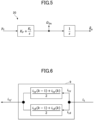
- FIG. 5 is a block diagram illustrating an example of a configuration of a phase synchronizer configured to generate a rotor phase estimated value and a rotor speed estimated value by converging the positive correlation signal p c to zero.
- the phase/speed estimator 10 includes a phase synchronizer 20.
- the phase synchronizer 20 is configured based on the digital generalized integral type PLL method.
- K p represents a proportionality constant
- K I represents an integration constant
- s represents a Laplace operator.
- the phase synchronizer 20 receives the positive correlation signal p c as an input signal, and outputs the phase ⁇ ⁇ ⁇ of the ⁇ semi-synchronous coordinate system (in this example, the phase of the ⁇ semi-synchronous coordinate system is equivalent to the rotor phase estimated value), and the speed ⁇ ⁇ of the ⁇ semi-synchronous coordinate system. Effectively, the coordinate system speed ⁇ ⁇ is the same as the rotor (electric) speed estimated value ⁇ 2n ⁇ .
- the phase/speed estimator 10 of the present embodiment can obtain these estimated values with a very small amount of computation.
- the phase/speed estimator 10 of the present embodiment applies a rectangular high-frequency voltage v ⁇ h having an amplitude V h on the ⁇ axis at the cycle Th corresponding to a frequency outside the human audible range.
- the high-frequency voltage v ⁇ h is applied at a frequency outside the audible range, it is possible to estimate the phase or the speed of the rotor by suppressing noise (a sound in the human audible range) that may be generated due to the application of the high-frequency voltage v ⁇ h .
- the frequency of the high-frequency voltage to be applied is set to be half the PWM frequency and the control frequency (i.e., the cycle of the high-frequency voltage to be applied is set to be twice the PWM cycle and the control cycle).
- the upper limit of the PWM frequency and the control frequency of both of which the control frequency is more of a hindrance, is restricted mainly due to the computing capability (processing speed) of the microcomputer, and the upper limit of these frequencies is currently approximately 20 kHz when considering a low-cost microcomputer to which sensor-less control is applied.
- the frequency of the high-frequency voltage to be applied is approximately 10 kHz, which is included in the human audible range.
- high-frequency noise sound in the human audible range
- the high-frequency voltage v ⁇ h is applied at a frequency outside the audible range, noise (sound in the human audible range) that may be generated due to application of the high-frequency voltage v ⁇ h can be suppressed.
- FIG. 3 (c) illustrates only the high-frequency current applied, but the detected stator current includes not only the current corresponding to the high-frequency component but also the current corresponding to the basic wave component for driving.
- the currents actually detected are expressed as follows.
- FIG. 6 is a block diagram illustrating an example of a configuration of the basic wave current converter.
- a 2-phase current i 1 resulting from conversion includes a ⁇ -axis current i 1 ⁇ and a ⁇ -axis current i 1 ⁇ .
- the basic wave current converter 9 can extract the drive current i 1f by applying the above relational equation to each of the ⁇ -axis current i 1 ⁇ and ⁇ -axis current i 1 ⁇ .
- the current detector 3 is not limited to a sensor such as a Current Transformer (CT) for detecting a current flowing in the AC motor 1, but may be one that detects a one-shunt current flowing in the direct-current side of the power inverter 2.
- CT Current Transformer
- the one-shunt current detection method is a method for detecting the phase current of each phase for controlling the motor, by using one shunt resistor connected to the DC bus line of the power inverter (see, e.g., PTLs 2 and 3).
- FIG. 7 is a timing chart for illustrating a state estimation method according to an embodiment in a case of controlling the drive of the AC motor by the one-shunt current detection method.
- the high-frequency voltage switching timings and the current detection timings do not necessarily coincide.
- application of a rectangular high-frequency voltage by the phase/speed estimator shall be performed at a timing synchronized with the temporally-discrete detection cycle to detect the stator current. This causes application of the rectangular high-frequency voltage v ⁇ h by the phase/speed estimator 10 to be performed synchronously with the temporally-discrete detection timing to detect the stator current.
Landscapes
- Engineering & Computer Science (AREA)
- Power Engineering (AREA)
- Control Of Ac Motors In General (AREA)
Applications Claiming Priority (3)
| Application Number | Priority Date | Filing Date | Title |
|---|---|---|---|
| JP2022087083 | 2022-05-27 | ||
| JP2023021523A JP2023174499A (ja) | 2022-05-27 | 2023-02-15 | 駆動制御装置、駆動制御システム及び状態推定方法 |
| PCT/JP2023/018820 WO2023228885A1 (ja) | 2022-05-27 | 2023-05-19 | 駆動制御装置、駆動制御システム及び状態推定方法 |
Publications (2)
| Publication Number | Publication Date |
|---|---|
| EP4535643A1 true EP4535643A1 (de) | 2025-04-09 |
| EP4535643A4 EP4535643A4 (de) | 2026-05-06 |
Family
ID=88919242
Family Applications (1)
| Application Number | Title | Priority Date | Filing Date |
|---|---|---|---|
| EP23811757.6A Pending EP4535643A4 (de) | 2022-05-27 | 2023-05-19 | Antriebssteuerungsvorrichtung, antriebssteuerungssystem und zustandsschätzungsverfahren |
Country Status (3)
| Country | Link |
|---|---|
| EP (1) | EP4535643A4 (de) |
| CN (1) | CN119343863A (de) |
| WO (1) | WO2023228885A1 (de) |
Families Citing this family (1)
| Publication number | Priority date | Publication date | Assignee | Title |
|---|---|---|---|---|
| JP2026042418A (ja) * | 2024-08-27 | 2026-03-11 | 株式会社日立産機システム | モータ制御装置およびモータ制御システム |
Family Cites Families (7)
| Publication number | Priority date | Publication date | Assignee | Title |
|---|---|---|---|---|
| JP6150211B2 (ja) * | 2013-08-09 | 2017-06-21 | 有限会社シー・アンド・エス国際研究所 | 交流電動機のデジタル式回転子位相速度推定装置 |
| JP6150212B2 (ja) * | 2013-08-18 | 2017-06-21 | 有限会社シー・アンド・エス国際研究所 | 交流電動機のデジタル式回転子位相速度推定装置 |
| JP6709014B2 (ja) | 2014-04-18 | 2020-06-10 | 日立オートモティブシステムズ株式会社 | インバータ装置 |
| JP2016021800A (ja) * | 2014-07-14 | 2016-02-04 | 株式会社リコー | 位置推定装置、モータ駆動制御装置及び位置推定方法 |
| JP7382885B2 (ja) | 2020-03-31 | 2023-11-17 | ミネベアミツミ株式会社 | モータ制御装置、モータシステム及びモータ制御方法 |
| JP7824057B2 (ja) | 2020-11-30 | 2026-03-04 | 積水化学工業株式会社 | 継手、排水設備、建物 |
| JP7776813B2 (ja) | 2021-08-02 | 2025-11-27 | 株式会社ブックアート | 書籍および書籍の製造方法 |
-
2023
- 2023-05-19 EP EP23811757.6A patent/EP4535643A4/de active Pending
- 2023-05-19 WO PCT/JP2023/018820 patent/WO2023228885A1/ja not_active Ceased
- 2023-05-19 CN CN202380042500.9A patent/CN119343863A/zh active Pending
Also Published As
| Publication number | Publication date |
|---|---|
| CN119343863A (zh) | 2025-01-21 |
| EP4535643A4 (de) | 2026-05-06 |
| WO2023228885A1 (ja) | 2023-11-30 |
Similar Documents
| Publication | Publication Date | Title |
|---|---|---|
| JP3979561B2 (ja) | 交流電動機の駆動システム | |
| EP1944860B1 (de) | Verfahren zur Schätzung der Rotordrehzahl und Position einer synchronen Permanentmagnetmaschine ohne Lagegeber | |
| JP5761243B2 (ja) | モータ制御装置および磁極位置推定方法 | |
| JP4059039B2 (ja) | 同期電動機の制御装置 | |
| JP5281339B2 (ja) | 同期電動機の駆動システム、及びこれに用いる制御装置 | |
| JP3692046B2 (ja) | モータ制御装置 | |
| JP5543388B2 (ja) | 永久磁石同期電動機の制御装置 | |
| JP2010172080A (ja) | 交流電動機の制御装置 | |
| JP4241218B2 (ja) | 交流電動機の制御装置及び交流電動機システム | |
| US20160352269A1 (en) | Apparatus for controlling rotary electric machine | |
| CN107078675A (zh) | 逆变器控制装置以及电机驱动系统 | |
| JP5333256B2 (ja) | 交流回転機の制御装置 | |
| EP4535643A1 (de) | Antriebssteuerungsvorrichtung, antriebssteuerungssystem und zustandsschätzungsverfahren | |
| JP2000156993A (ja) | 永久磁石型同期機の制御装置及びその制御方法 | |
| JP4590761B2 (ja) | 永久磁石形同期電動機の制御装置 | |
| US9240744B2 (en) | Methods, systems and apparatus for adjusting current and/or torque commands used to control operation of an asynchronous machine | |
| JP6806272B1 (ja) | モータの減磁診断装置およびモータ制御装置の減磁診断方法 | |
| Ying et al. | An observer-based three-phase current reconstruction using DC link measurement in PMAC motors | |
| JP4632157B2 (ja) | 永久磁石モータの駆動システム | |
| JP2009142073A (ja) | 回転機の制御装置及び制御システム | |
| JP2016163515A (ja) | 同期機制御装置及び駆動システム | |
| JP2023174499A (ja) | 駆動制御装置、駆動制御システム及び状態推定方法 | |
| JP3578096B2 (ja) | モータ制御装置 | |
| JP2016036195A (ja) | モータ制御装置及び冷蔵庫 | |
| Kumar et al. | Direct torque control method for induction motor drives based on modified amplitude and angle decoupled control of stator flux |
Legal Events
| Date | Code | Title | Description |
|---|---|---|---|
| STAA | Information on the status of an ep patent application or granted ep patent |
Free format text: STATUS: THE INTERNATIONAL PUBLICATION HAS BEEN MADE |
|
| PUAI | Public reference made under article 153(3) epc to a published international application that has entered the european phase |
Free format text: ORIGINAL CODE: 0009012 |
|
| STAA | Information on the status of an ep patent application or granted ep patent |
Free format text: STATUS: REQUEST FOR EXAMINATION WAS MADE |
|
| 17P | Request for examination filed |
Effective date: 20241126 |
|
| AK | Designated contracting states |
Kind code of ref document: A1 Designated state(s): AL AT BE BG CH CY CZ DE DK EE ES FI FR GB GR HR HU IE IS IT LI LT LU LV MC ME MK MT NL NO PL PT RO RS SE SI SK SM TR |
|
| DAV | Request for validation of the european patent (deleted) | ||
| DAX | Request for extension of the european patent (deleted) | ||
| P01 | Opt-out of the competence of the unified patent court (upc) registered |
Free format text: CASE NUMBER: UPC_APP_0003839_4535643/2026 Effective date: 20260203 |