EP4535657A1 - Leistungsverstärkungsvorrichtung, fernfunkeinheit, basisstation und kommunikationssystem - Google Patents
Leistungsverstärkungsvorrichtung, fernfunkeinheit, basisstation und kommunikationssystem Download PDFInfo
- Publication number
- EP4535657A1 EP4535657A1 EP22953444.1A EP22953444A EP4535657A1 EP 4535657 A1 EP4535657 A1 EP 4535657A1 EP 22953444 A EP22953444 A EP 22953444A EP 4535657 A1 EP4535657 A1 EP 4535657A1
- Authority
- EP
- European Patent Office
- Prior art keywords
- power amplifier
- port
- unit
- circulator
- amplifier unit
- Prior art date
- Legal status (The legal status is an assumption and is not a legal conclusion. Google has not performed a legal analysis and makes no representation as to the accuracy of the status listed.)
- Pending
Links
Images










Classifications
-
- H—ELECTRICITY
- H04—ELECTRIC COMMUNICATION TECHNIQUE
- H04B—TRANSMISSION
- H04B1/00—Details of transmission systems, not covered by a single one of groups H04B3/00 - H04B13/00; Details of transmission systems not characterised by the medium used for transmission
- H04B1/02—Transmitters
- H04B1/04—Circuits
- H04B1/0483—Transmitters with multiple parallel paths
-
- H—ELECTRICITY
- H03—ELECTRONIC CIRCUITRY
- H03F—AMPLIFIERS
- H03F1/00—Details of amplifiers with only discharge tubes, only semiconductor devices or only unspecified devices as amplifying elements
- H03F1/02—Modifications of amplifiers to raise the efficiency, e.g. gliding Class A stages, use of an auxiliary oscillation
- H03F1/0205—Modifications of amplifiers to raise the efficiency, e.g. gliding Class A stages, use of an auxiliary oscillation in transistor amplifiers
- H03F1/0288—Modifications of amplifiers to raise the efficiency, e.g. gliding Class A stages, use of an auxiliary oscillation in transistor amplifiers using a main and one or several auxiliary peaking amplifiers whereby the load is connected to the main amplifier using an impedance inverter, e.g. Doherty amplifiers
-
- H—ELECTRICITY
- H03—ELECTRONIC CIRCUITRY
- H03F—AMPLIFIERS
- H03F1/00—Details of amplifiers with only discharge tubes, only semiconductor devices or only unspecified devices as amplifying elements
- H03F1/56—Modifications of input or output impedances, not otherwise provided for
-
- H—ELECTRICITY
- H03—ELECTRONIC CIRCUITRY
- H03F—AMPLIFIERS
- H03F3/00—Amplifiers with only discharge tubes or only semiconductor devices as amplifying elements
- H03F3/189—High-frequency amplifiers, e.g. radio frequency amplifiers
- H03F3/19—High-frequency amplifiers, e.g. radio frequency amplifiers with semiconductor devices only
- H03F3/195—High-frequency amplifiers, e.g. radio frequency amplifiers with semiconductor devices only in integrated circuits
-
- H—ELECTRICITY
- H03—ELECTRONIC CIRCUITRY
- H03F—AMPLIFIERS
- H03F3/00—Amplifiers with only discharge tubes or only semiconductor devices as amplifying elements
- H03F3/20—Power amplifiers, e.g. Class B amplifiers, Class C amplifiers
- H03F3/21—Power amplifiers, e.g. Class B amplifiers, Class C amplifiers with semiconductor devices only
- H03F3/211—Power amplifiers, e.g. Class B amplifiers, Class C amplifiers with semiconductor devices only using a combination of several amplifiers
-
- H—ELECTRICITY
- H03—ELECTRONIC CIRCUITRY
- H03F—AMPLIFIERS
- H03F3/00—Amplifiers with only discharge tubes or only semiconductor devices as amplifying elements
- H03F3/20—Power amplifiers, e.g. Class B amplifiers, Class C amplifiers
- H03F3/24—Power amplifiers, e.g. Class B amplifiers, Class C amplifiers of transmitter output stages
- H03F3/245—Power amplifiers, e.g. Class B amplifiers, Class C amplifiers of transmitter output stages with semiconductor devices only
-
- H—ELECTRICITY
- H04—ELECTRIC COMMUNICATION TECHNIQUE
- H04B—TRANSMISSION
- H04B1/00—Details of transmission systems, not covered by a single one of groups H04B3/00 - H04B13/00; Details of transmission systems not characterised by the medium used for transmission
- H04B1/02—Transmitters
- H04B1/04—Circuits
- H04B1/0458—Arrangements for matching and coupling between power amplifier and antenna or between amplifying stages
-
- H—ELECTRICITY
- H03—ELECTRONIC CIRCUITRY
- H03F—AMPLIFIERS
- H03F2200/00—Indexing scheme relating to amplifiers
- H03F2200/451—Indexing scheme relating to amplifiers the amplifier being a radio frequency amplifier
-
- H—ELECTRICITY
- H03—ELECTRONIC CIRCUITRY
- H03F—AMPLIFIERS
- H03F2203/00—Indexing scheme relating to amplifiers with only discharge tubes or only semiconductor devices as amplifying elements covered by H03F3/00
- H03F2203/20—Indexing scheme relating to power amplifiers, e.g. Class B amplifiers, Class C amplifiers
- H03F2203/21—Indexing scheme relating to power amplifiers, e.g. Class B amplifiers, Class C amplifiers with semiconductor devices only
- H03F2203/211—Indexing scheme relating to power amplifiers, e.g. Class B amplifiers, Class C amplifiers with semiconductor devices only using a combination of several amplifiers
- H03F2203/21142—Output signals of a plurality of power amplifiers are parallel combined to a common output
-
- H—ELECTRICITY
- H04—ELECTRIC COMMUNICATION TECHNIQUE
- H04B—TRANSMISSION
- H04B1/00—Details of transmission systems, not covered by a single one of groups H04B3/00 - H04B13/00; Details of transmission systems not characterised by the medium used for transmission
- H04B1/02—Transmitters
- H04B1/04—Circuits
- H04B2001/0408—Circuits with power amplifiers
- H04B2001/045—Circuits with power amplifiers with means for improving efficiency
Definitions
- This application relates to the field of communication technologies, and in particular, to a power amplifier apparatus, a remote radio unit, a base station, and a communication system.
- a power amplifier (Power Amplifier, PA) is an important component in a wireless communication base station.
- the power amplifier may be referred to as a power amplifier for short.
- Efficiency of the power amplifier determines power consumption, a size, a thermal design, and the like of the base station.
- modulation signals with a plurality of different standards are used in wireless communication, for example, orthogonal frequency division multiplexing (orthogonal frequency division multiplexing, OFMA), code division multiple access (code division multiple access, CDMA), and time division multiple access (time division multiple access, TDMA).
- OFMA orthogonal frequency division multiplexing
- code division multiple access code division multiple access
- TDMA time division multiple access
- the signals with these standards have different peak-to-average power ratios (peak-to-average power ratios, PAPRs).
- a peak-to-average power ratio of an OFDM signal is 10 dB to 12 dB.
- the power amplifier usually uses a power back-off method.
- the power amplifier works in a class A state or class AB state, and enters a linear working region away from a saturation region, to improve linearity of the power amplifier.
- the method causes a significant decrease in the efficiency of the power amplifier, and increases the energy consumption of the base station under same output power.
- This application provides a power amplifier apparatus, a remote radio unit, a base station, and a communication system, to reduce energy consumption of the power amplifier apparatus, thereby reducing power consumption of the base station.
- the first power amplifier unit is configured to amplify a received signal, and input an amplified signal into the first port.
- the second power amplifier unit is configured to amplify a received signal, and input an amplified signal into the second port. Because the circulator unit has a unidirectional transmission characteristic, the circulator unit may transmit, to the second port, the signal received through the first port, and then may modulate load impedance of the second power amplifier unit. Therefore, the power amplifier apparatus may improve efficiency of the power amplifier apparatus at high back-off power according to an active load modulation principle, to reduce energy consumption of the power amplifier apparatus, and further reduce power consumption of a base station configured with the power amplifier apparatus.
- the first power amplifier unit and the second power amplifier unit may be components of a radio frequency transmit channel
- the third power amplifier unit may be a component of a radio frequency receive channel. Switching between the radio frequency transmit channel and the radio frequency receive channel may be implemented by using the first switch.
- the power amplifier apparatus may implement combination and switching between a transmit link and a receive link by using the circulator unit.
- the power amplifier apparatus does not need to be connected to an external circulator for implementing the switching between the transmit link and the receive link, so that an insertion loss of the transmit link in the communication system can be reduced.
- the third port of the circulator unit is connected to an antenna.
- the circulator unit may transmit a signal of a radio frequency transmit channel via the antenna connected to the third port, to implement an air interface connection between a communication apparatus configured with the power amplifier apparatus and a terminal device.
- the first power amplifier unit may be considered to be in an isolated state relative to the second power amplifier unit.
- impedance of a port on a side of the first power amplifier unit may be close to a constant value, and an LPR of the first power amplifier unit may be close to 1, that is, there is no load pulling.
- a load-pull ratio closer to 1 indicates a better wideband characteristic of a matching network of a power amplifier unit. Therefore, a wideband characteristic of a matching network of the first power amplifier unit is good.
- the first power amplifier unit is a main power amplifier unit, and the second power amplifier unit is an auxiliary power amplifier unit; or the first power amplifier unit is an auxiliary power amplifier unit, and the second power amplifier unit is a main power amplifier unit.
- the first power amplifier unit is a main power amplifier unit
- smaller power of a power transistor selected by the first power amplifier unit indicates a larger power back-off amount that can be implemented by the power amplifier apparatus.
- smaller power of a power transistor selected by the main power amplifier unit indicates larger optimal impedance Ropt of the main power amplifier unit.
- characteristic impedance of an impedance transformation line in a matching network of a main power amplifier needs to reach the optimal impedance Ropt.
- the circulator unit is disposed in the power amplifier apparatus, and impedance of a port of the circulator unit is usually a small value, for example, may be usually 50 ohms (ohms).
- the power amplifier apparatus further includes a first signal decomposition module.
- An output port of the first signal decomposition module is separately connected to an input port of the first power amplifier unit and an input port of the second power amplifier unit.
- the first signal decomposition module is configured to obtain at least two paths of signals based on a received radio frequency signal, and respectively input the signals in the at least two paths of signals into the first power amplifier unit and the second power amplifier unit.
- the first signal decomposition module is configured to control amplitudes and/or phases of the two paths of signals input into the first power amplifier unit and the second power amplifier unit.
- the first signal decomposition module may perform digital amplitude modulation and phase modulation or analog amplitude modulation and phase modulation on the two paths of signals input into the first power amplifier unit and the second power amplifier unit.
- the amplitudes and/or the phases of the two paths of signals of the first power amplifier unit and the second power amplifier unit may be controlled to alleviate an "efficiency dip" problem.
- the first power amplifier unit is a main power amplifier unit
- the second power amplifier unit is an auxiliary power amplifier unit.
- the first signal decomposition module is specifically configured to: after the second power amplifier unit is enabled, control a value of a current of the signal input into the second power amplifier unit to increase as output power of the power amplifier apparatus increases, and control a value of a current of the signal input into the first power amplifier unit to decrease as the output power of the power amplifier apparatus increases; and when the value of the current of the signal input into the first power amplifier unit is less than a preset first current value, control a phase of the current of the signal input into the first power amplifier unit to rotate by 180 degrees, and control the value of the current of the signal input into the first power amplifier unit to increase as the output power of the power amplifier apparatus increases.
- an additional efficiency peak point may be generated in a medium-power region of the power amplifier apparatus, to alleviate an "efficiency dip" problem, and improve overall performance of the power amplifier apparatus.
- the power amplifier apparatus further includes a second signal decomposition module.
- An output port of the second signal decomposition module is connected to an input port of the first power amplifier unit.
- the second signal decomposition module is configured to divide a received radio frequency signal into K1 channels of signals, and input the signals in the K1 channels of signals into input ports of K1 power amplifier subunits of the first power amplifier unit.
- K1 is an integer greater than 1.
- the power amplifier apparatus further includes a third signal decomposition module.
- the output port of the first power amplifier unit is selectively connected to the first port or an input port of the third signal decomposition module by using the second switch.
- An output port of the third signal decomposition module is connected to the input port of the second power amplifier unit.
- the third signal decomposition module is configured to divide a received radio frequency signal into K2 channels of signals, and input the signals in the K2 channels of signals into input ports of K2 power amplifier subunits of the second power amplifier unit.
- K2 is an integer greater than 1. Because of a high-efficiency power amplifier architecture nested in the second power amplifier unit, a back-off amount of the power amplifier apparatus may be further increased, back-off efficiency may also be improved, and a large quantity of peak points may be added in a medium-power region, so that an "efficiency dip" problem can be alleviated.
- the third port of the circulator unit is connected to an antenna.
- the circulator unit may transmit a signal of a radio frequency transmit channel via the antenna connected to the third port, to implement an air interface connection between a communication apparatus configured with the power amplifier apparatus and a terminal device.
- the first power amplifier unit is a main power amplifier unit or an auxiliary power amplifier unit
- the second power amplifier unit is of a power amplifier type different from that of the first power amplifier unit in the main power amplifier unit and the auxiliary power amplifier unit. In this case, solution flexibility can be improved.
- an embodiment of this application provides a remote radio unit, including the power amplifier apparatus according to any one of the first aspect and the possible implementations of the first aspect.
- an embodiment of this application provides a remote radio unit, including the power amplifier apparatus according to any one of the second aspect and the possible implementations of the second aspect.
- an embodiment of this application provides a communication system, including a baseband processing unit, at least one power amplifier apparatus according to any one of the first aspect and the possible implementations of the first aspect that is connected to the baseband processing unit, and an antenna connected to the third port of the circulator unit in the power amplifier apparatus.
- an embodiment of this application provides a communication system, including a baseband processing unit, at least one power amplifier apparatus according to any one of the second aspect and the possible implementations of the second aspect that is connected to the baseband processing unit, and an antenna connected to the third port of the circulator unit in the power amplifier apparatus.
- FIG. 1 is an example diagram of a scenario to which an embodiment of this application is applicable.
- a device that provides a wireless network service is a base station
- a device that uses a wireless network service is a terminal
- the devices that provide the wireless network service are devices that are a part of a wireless communication network, and may be referred to as network devices (network devices) or network elements (network elements) for short.
- the network device generally belongs to an operator or an infrastructure provider, and is operated or maintained by these vendors.
- the network devices may be further classified into radio access network (radio access network, RAN) devices and core network (core network, CN) devices.
- RAN radio access network
- core network core network
- a typical RAN device includes a base station (base station, BS).
- the base station sometimes may be also referred to as a wireless access point (access point, AP) or a transmission reception point (transmission reception point, TRP).
- the base station may be a generation NodeB (generation NodeB, gNB) in a 5G new radio (new radio, NR) system or an evolved NodeB (evolved NodeB, eNB) in a 4G long term evolution (long term evolution, LTE) system.
- Base stations may be classified into macro base stations (macro base stations) and micro base stations (micro base stations) based on different physical forms or transmit power of the base stations.
- the micro base station sometimes is also referred to as a small base station or a small cell (small cell).
- the device that uses the wireless network service may be referred to as a terminal (terminal) for short. Still refer to FIG. 1 .
- the terminal can establish a connection to the network device, and provide a specific wireless communication service for a user based on the service of the network device.
- the terminal sometimes is also referred to as user equipment (user equipment, UE) or a subscriber unit (subscriber unit, SU).
- UE user equipment
- subscriber unit subscriber unit
- SU subscriber unit
- the terminal in comparison with a base station that is generally placed at a fixed location, the terminal usually moves along with the user, and sometimes is also referred to as a mobile station (mobile station, MS).
- some network devices such as relay nodes (relay nodes, RNs) or wireless routers sometimes may also be considered as terminals because the network devices have UE identities or belong to the user.
- the terminal may be a mobile phone (mobile phone), a tablet computer (tablet computer), a laptop computer (laptop computer), a wearable device (for example, a smart watch, a smart band, a smart helmet, or smart glasses), or another device that has a wireless access capability, for example, an intelligent vehicle or various internet of things (internet of things, IoT) devices including various smart home devices (such as a smart meter and a smart home appliance) and smart city devices (such as a security or monitoring device and an intelligent road transportation facility).
- IoT internet of things
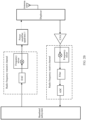
- FIG. 2A shows some common components for radio frequency signal processing in the communication system.
- the communication system includes a baseband subsystem.
- a to-be-sent signal generated by the baseband subsystem may be sent through a radio frequency transmit channel.
- the radio frequency transmit channel may include components such as a digital-to-analog converter (digital-to-analog converter, DAC) and a frequency mixer.
- DAC digital-to-analog converter
- DAC digital-to-analog converter
- filtering processing may be further performed by using a filter, and then the output signal is transmitted via the antenna.
- FIG. 3A is an example diagram of a possible structure of a power amplifier apparatus 1 according to an embodiment of this application.
- the power amplifier apparatus 1 shown in FIG. 3A may be the power amplifier apparatus 1 shown in FIG. 2A .
- the circulator unit in this embodiment of this application may include one or more circulators.
- the circulator is a component in which an incident wave (a signal) entering any port of the circulator unit is sequentially transmitted to a next port or a plurality of ports in a direction determined by a static bias magnetic field.
- FIG. 3A an example in which the circulator unit 4 includes one circulator, and a transmission direction of a signal in the circulator is a clockwise direction is used for illustration.
- Four or more ports are provided on the circulator unit 4.
- FIG. 3A an example in which four ports are provided on the circulator unit 4 is used for description.
- the circulator unit 4 includes a first port 41, a second port 42, a third port 43, and a fourth port 44.
- An output port of the first power amplifier unit 2 is connected to the first port 41.
- An output port of the second power amplifier unit 3 is connected to the second port 42.
- the fourth port 44 of the circulator unit 4 is selectively connected to a load 7 or a third power amplifier unit 8 by using a first switch 6.
- the load 7 may be, for example, a resistor. Impedance of the resistor may be the same as or close to impedance of a port of the circulator. For example, if impedance of the fourth port is 50 ohms (ohms), the impedance of the load 7 may also be 50 ohms (ohms), so that the impedance of the load matches the impedance of the port of the circulator connected to the load.
- FIG. 3A also shows the third power amplifier unit 8.
- the third power amplifier unit 8 may be a power amplifier connected to a radio frequency receive channel.
- the third power amplifier unit 8 may include one or more power amplifiers.
- the third power amplifier unit 8 may be the LNA in FIG. 2A .
- the power amplifier apparatus may implement switching between a radio frequency transmit channel and the radio frequency receive channel by using the first switch 6.
- the radio frequency transmit channel is in a working state.
- the fourth port 44 may be connected to the load 7 by using the first switch 6.
- the circulator unit 4 may transmit, to the second port 42 and the third port 43, a signal received through the first port 41 (for example, the circulator unit 4 may sequentially transmit, to the second port 42 and the third port 43, a signal received through the first port 41), and output, through the third port 43, a signal received through the second port 42.
- the third port 43 may be connected to another component (such as a filter). Impedance of the component connected to the third port 43 is set to a value that is the same as or close to impedance of the third port 43. In this case, the impedance of the component connected to the third port 43 is close to matching the impedance of the third port 43. Therefore, almost all of signals received through the first port 41 and the second port 42 can be transmitted outside through the third port 43.
- another component such as a filter
- the circulator unit 4 may transmit, to the second port 42, the signal received through the first port 41, and then may modulate load impedance of the second power amplifier unit 3. Therefore, the power amplifier apparatus 1 may improve efficiency of the power amplifier apparatus 1 at high back-off power according to an active load modulation principle, to reduce energy consumption of the power amplifier apparatus 1, and further reduce power consumption of a base station configured with the power amplifier apparatus 1.
- the characteristic of the circulator unit 4 is that a signal entering any port of the circulator unit 4 is sequentially transmitted to a next port or a plurality of ports in the direction determined by the static bias magnetic field, and the signal received by the circulator unit 4 through the first port may be transmitted to the second port 42 and the third port 43 (for example, the signal received by the circulator unit 4 through the first port may be sequentially transmitted to the second port 42 and the third port 43), the first power amplifier unit may be considered to be in an isolated state relative to the second power amplifier unit.
- impedance of a port on a side of the first power amplifier unit may be close to a constant value, and a load-pull ratio (load-pull ratio, LPR) of the first power amplifier unit may be close to 1, that is, there is no load pulling.
- a load-pull ratio closer to 1 indicates a better wideband characteristic of a matching network of a power amplifier unit. Therefore, a wideband characteristic of a matching network of the first power amplifier unit 2 is good.
- the first power amplifier unit 2 when the first power amplifier unit 2 is a main power amplifier unit, smaller power of a power transistor selected by the first power amplifier unit 2 indicates a larger power back-off amount that can be implemented by the power amplifier apparatus 1.
- smaller power of a power transistor selected by the main power amplifier unit indicates larger optimal impedance Ropt of the main power amplifier unit.
- characteristic impedance of an impedance transformation line in a matching network of a main power amplifier needs to reach the optimal impedance Ropt. Because larger characteristic impedance of the impedance transformation line indicates a narrower microstrip, if power of a power transistor in the main power amplifier is set to a small value in the DHT solution, a physical implementation based on a distributed microstrip structure is difficult.
- the circulator unit is disposed in the power amplifier apparatus, and impedance of a port of the circulator unit is usually a small value, for example, may be usually 50 ohms (ohms).
- the radio frequency receive channel is in a working state.
- the fourth port 44 may be connected to the third power amplifier unit 8 by using the first switch 6.
- the third power amplifier unit 8 may be, for example, the LNA in FIG. 2A .
- the circulator unit 4 is configured to output, to the third power amplifier unit 8 through the fourth port 44, a signal received through the third port 43.
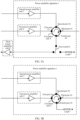
- FIG. 3B and FIG. 3C are example diagrams of several other possible structures of a power amplifier apparatus 1 according to embodiments of this application.
- the power amplifier apparatus 1 shown in FIG. 3B and FIG. 3C may be the power amplifier apparatus 1 shown in FIG. 2B . It can be learned from FIG. 2B that the power amplifier apparatus 1 provided in embodiments of this application may not need to have a function of implementing switching between a radio frequency transmit channel and a radio frequency receive channel. Therefore, in comparison with FIG. 3A , a fourth port 44 of a circulator unit 4 in FIG. 3B may be directly connected to a load 7, and a first switch 6 does not need to be disposed in the power amplifier apparatus 1. In comparison with FIG. 3A , a circulator unit 4 in FIG. 3C may not include a fourth port 44, and the power amplifier apparatus also does not need to include a first switch 6 or a load 7 connected to the fourth port 44.
- the power amplifier apparatus 1 includes M power amplifier units and the circulator unit 4, and the M power amplifier units are connected to the circulator unit 4.
- the circulator unit 4 may be configured to transmit, to a second port 42 and a third port 43, a signal received through a first port 41, and output, through the third port 43, a signal received through the second port 42.
- the circulator unit 4 may transmit, to the second port 42, the signal received through the first port 41, and then may modulate load impedance of a second power amplifier unit 3. Therefore, the power amplifier apparatus 1 may improve efficiency of the power amplifier apparatus 1 at high back-off power according to an active load modulation principle, to reduce energy consumption of the power amplifier apparatus 1, and further reduce power consumption of a base station configured with the power amplifier apparatus 1.
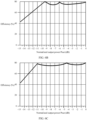
- FIG. 4A shows an example in which a first power amplifier unit 2 is a main power amplifier unit, a second power amplifier unit 3 is an auxiliary power amplifier unit, the first power amplifier unit includes one power amplifier, the second power amplifier unit includes one power amplifier, and a power ratio of maximum output power of the first power amplifier unit to maximum output power of the second power amplifier unit is 1:8.
- a working region of the power amplifier apparatus 1 may be roughly divided into three stages: a low-power region, a medium-power region, and a high-power region. The following describes the foregoing three stages in detail with reference to the diagram of the efficiency curve of the power amplifier apparatus 1 in FIG. 4A .
- Low-power region (a region in which normalized output power of the power amplifier apparatus in FIG. 4A is less than -9.5 dB)
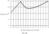
- FIG. 4B shows an example in which a first power amplifier unit 2 is an auxiliary power amplifier unit, a second power amplifier unit 3 is a main power amplifier unit, the first power amplifier unit includes one power amplifier, the second power amplifier unit includes one power amplifier, the first power amplifier unit is an auxiliary power amplifier unit, the second power amplifier unit is a main power amplifier unit, and a power ratio of maximum output power of the first power amplifier unit to maximum output power of the second power amplifier unit is 1:1.
- a difference in the diagram of the efficiency curve shown in FIG. 4B lies in that a power back-off point corresponding to a first high-power point of the power amplifier apparatus 1 is -11 dB, a low-power region of the power amplifier apparatus 1 shown in FIG. 4B is a region in which normalized output power is less than -11 dB, and a medium-power region is a region in which normalized output power Pout is between -11 dB and 0 dB.
- the main power amplifier unit in the power amplifier apparatus 1 provided in embodiments of this application is flexibly set, and any one of M power amplifier units may be used as a main power amplifier unit.
- a large power back-off amount of the power amplifier apparatus 1 can be implemented by setting a power ratio of the power amplifier units.
- a signal sent by the first power amplifier unit needs to additionally pass through a link from the first port 41 to the second port 42. Therefore, in comparison with a solution in which the first power amplifier unit is used as a main power amplifier unit, if the first power amplifier unit is used as an auxiliary power amplifier unit, the first power amplifier unit may be enabled later, to reduce a quantity of signals that need to be transmitted on the link from the first port 41 to the second port 42, and further reduce an insertion loss of an output matching network.
- FIG. 5A is an example diagram of another possible structure of a communication system according to an embodiment of this application.
- the embodiment shown in FIG. 5A may be considered as an extended embodiment of the foregoing embodiments of FIG. 3A, FIG. 3B , and FIG. 3C .
- FIG. 5A uses an architecture of the power amplifier apparatus 1 shown in FIG. 3A as an example for illustration.
- the embodiment in FIG. 5A is also applicable to the foregoing embodiment shown in FIG. 3B .
- a fourth port 44 in the power amplifier apparatus 1 in the embodiment shown in FIG. 5A is directly connected to a load 7, the power amplifier apparatus 1 does not include a first switch 6, and other content is applicable to embodiments shown in FIG. 3A and FIG. 3B . Details are not described subsequently again.
- the embodiment in FIG. 5A is also applicable to the foregoing embodiment shown in FIG. 3C .
- the power amplifier apparatus 1 in the embodiment shown in FIG. 5A does not include a fourth port 44, a first switch 6, or a load 7, and other content is applicable to embodiments shown in FIG. 3A and FIG. 3C . Details are not described subsequently again.
- a third port 43 of a circulator unit 4 in this embodiment of this application may be connected to an antenna.
- the third port 43 of the circulator unit 4 may be used as an output port of the power amplifier apparatus, the third port may be connected to a filter, and the filter is connected to the antenna.
- a signal received through the third port 43 of the circulator unit 4 from another port of the circulator unit may be sent to the antenna through the third port 43, to be transmitted via the antenna.
- a signal received by the antenna may be transmitted to the fourth port 44 through the third port 43 of the circulator unit 4, and then transmitted to a third power amplifier unit 8 through the fourth port 44.
- the power amplifier apparatus 1 shown in FIG. 5A further includes a first signal decomposition module 9. It may also be understood as that the power amplifier apparatus 1 shown in FIG. 3A, FIG. 3B , or FIG. 3C may also include the first signal decomposition module 9.
- An output port of the first signal decomposition module 9 is separately connected to an input port of a first power amplifier unit 2 and an input port of a second power amplifier unit 3.
- the first signal decomposition module 9 is configured to obtain at least two paths of signals based on a received radio frequency signal, and respectively input the signals in the at least two paths of signals into the first power amplifier unit 2 and the second power amplifier unit 3.
- the first signal decomposition module 9 is configured to control amplitudes and/or phases of the two paths of signals input into the first power amplifier unit 2 and the second power amplifier unit 3.
- the first signal decomposition module 9 may perform digital amplitude modulation and phase modulation or analog amplitude modulation and phase modulation on the two paths of signals input into the first power amplifier unit 2 and the second power amplifier unit 3.
- the power amplifier apparatus 1 can improve efficiency of the medium-power region, there is an "efficiency dip" in the medium-power region.
- this embodiment of this application provides a possible implementation.
- the first power amplifier unit 2 is a main power amplifier
- the second power amplifier unit 3 is an auxiliary power amplifier.
- the first signal decomposition module 9 is specifically configured to:
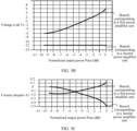
- FIG. 5B is an example curve diagram of voltages of the first power amplifier unit and the second power amplifier unit in FIG. 5A and normalized output power Pout
- FIG. 5C is an example curve diagram of currents of the first power amplifier unit and the second power amplifier unit in FIG. 5A and normalized output power Pout
- FIG. 5D is an example curve diagram of efficiency of the first power amplifier unit and the second power amplifier unit in FIG. 5A and normalized output power Pout.
- amplitudes and phases of the currents of the signals input into the first power amplifier unit and the second power amplifier unit may be adjusted in real time based on the output power of the power amplifier apparatus 1.
- FIG. 5C merely provides a possible example, and adjustment may be performed based on an actual situation during actual application.
- the solutions shown in FIG. 5A , FIG. 5B, and FIG. 5C may also be applicable to the power amplifier apparatus 1 shown in FIG. 3B or FIG. 3C .
- the first power amplifier unit 2 and the second power amplifier unit 3 in FIG. 3B or FIG. 3C may also be connected to the first signal decomposition module 9.
- the first signal decomposition module 9 digitally controls, based on curves shown in FIG. 5C , the amplitudes and the phases of the two paths of signals input into the first power amplifier unit 2 and the second power amplifier unit 3. Therefore, an additional efficiency peak point may be generated in the medium-power region of the power amplifier apparatus 1 in FIG. 3B or FIG. 3C , to alleviate the "efficiency dip".
- Related content is similar to the foregoing content, and details are not described again.
- FIG. 6A is an example diagram of another possible structure of a communication system according to an embodiment of this application.
- the embodiment shown in FIG. 6A may be considered as an extended embodiment of the foregoing embodiment of FIG. 3A, FIG. 3B , or FIG. 3C , or may be used in combination with the foregoing embodiments shown in FIG. 5A , FIG. 5B , FIG. 5C , and FIG. 5D .
- an architecture of the power amplifier apparatus 1 shown in FIG. 3A is used as an example for illustration.
- the embodiment in FIG. 6A is also applicable to the foregoing embodiment shown in FIG. 3B or FIG. 3C .
- a second power amplifier unit includes N2 power amplifier subunits and a second combiner 33.
- N2 is an integer greater than 1. Any one of the N2 power amplifier subunits may include one or more power amplifiers.
- N2 is 2, one of the power amplifier subunits includes a PA 31, and the other power amplifier subunit includes a PA 32 is used for illustration.
- Output ports of the N2 power amplifier subunits are connected to an input port of the second combiner 33, and an output port of the second combiner 33 is connected to a second port 42 of a circulator unit 4.
- Each of the N2 power amplifier subunits is configured to amplify a received signal, and input an amplified signal into the second combiner 33.
- the second combiner 33 is configured to input the signal received from the power amplifier subunit in the N2 power amplifier subunits into the second port 42.
- the second combiner 33 may include one or more impedance transforming networks (for example, quarter-wave impedance transforming networks).
- FIG. 6A further shows an example of impedance transforming networks in the first power amplifier unit 2 and the second power amplifier unit 3.
- the impedance transforming networks may implement impedance matching of a main power amplifier unit in a high-impedance state (a low-power region) and impedance pulling inverse of the main power amplifier unit after an auxiliary power amplifier unit is enabled.
- a quantity and locations of the impedance transforming networks shown in FIG. 6A are merely examples. In an actual application function, the impedance transforming network may be deployed as required.
- the solutions shown in FIG. 6A , FIG. 6B, and FIG. 6C may also be applicable to the power amplifier apparatus 1 shown in FIG. 3B or FIG. 3C .
- the first power amplifier unit 2 and the second power amplifier unit 3 in FIG. 3B or FIG. 3C may also be the first power amplifier unit 2 and the second power amplifier unit 3 in FIG. 6A . Therefore, an additional efficiency peak point may be generated in the medium-power region of the power amplifier apparatus 1, to alleviate the "efficiency dip".
- Related content is similar to the foregoing content, and details are not described again.
- FIG. 7A, FIG. 7B , and FIG. 7C are example diagrams of several possible structures of a power amplifier unit 10 in M power amplifier units according to embodiments of this application.
- the power amplifier unit 10 shown in any one or more of FIG. 7A, FIG. 7B , and FIG. 7C may be a diagram of a structure of any one or more of the M power amplifier units.
- the power amplifier unit in any one of FIG. 7A, FIG. 7B , and FIG. 7C may be the first power amplifier unit 2 in FIG. 3A, FIG. 3B , and FIG. 3C , or may be the second power amplifier unit 3 in FIG. 3A, FIG. 3B , and FIG. 3C .
- the power amplifier unit 10 of a power amplifier apparatus 1 may include three power amplifier subunits. Each power amplifier subunit includes one power amplifier. The three power amplifier subunits are respectively a PA 101, a PA 102, and a PA 103. The three power amplifier subunits are combined into one channel by using a combiner. For example, the PA 101 and the PA 102 are combined with the PA 103.
- a diagram of an architecture of the power amplifier unit shown in FIG. 7B may also be considered as an architecture of multi-way Doherty PA ⁇ Sequential PA ⁇ Chireix PA.
- the power amplifier unit 10 of a power amplifier apparatus 1 may include two power amplifier subunits. Each power amplifier subunit includes one power amplifier. The two power amplifier subunits are combined by using a combiner.
- a diagram of an architecture of the power amplifier unit shown in FIG. 7C may also be considered as an architecture of an outphasing PA. In the architecture, two power amplifier branches combined by using the combiner may be understood as an outphasing (outphasing) combination.
- the power amplifier unit 10 shown in any one of FIG. 7A, FIG. 7B , and FIG. 7C may be single-input, or may be multiple-input.
- a phase and an amplitude of a signal received by each power amplifier in the power amplifier unit 10 are fixed and nonadjustable.
- a signal decomposition module (for example, a first signal decomposition module 9) connected to the power amplifier unit 10 may be a radio frequency analog circuit.
- a phase and an amplitude of a signal received by each power amplifier in the power amplifier unit 10 may be flexibly adjustable.
- a signal received by the power amplifier unit 10 from a signal decomposition module (for example, a first signal decomposition module 9) may be a digital excitation radio frequency signal.
- An input port of the power amplifier unit 10 shown in FIG. 7A, FIG. 7B , and FIG. 7C may be connected to an output port of the first signal decomposition module 9, and an output port of the power amplifier unit 10 may be connected to a port of a circulator unit 4.
- the power amplifier apparatus 1 may add an efficiency peak point of the power amplifier apparatus 1, to alleviate an "efficiency dip" problem in a medium-power region, and improve overall performance of the power amplifier apparatus.
- an additional efficiency peak point may be generated in a medium-power region, to alleviate an "efficiency dip".
- the solution shown in FIG. 7D may also be applicable to the power amplifier apparatus 1 shown in FIG. 3B or FIG. 3C .
- the first power amplifier unit 2 and the second power amplifier unit 3 in FIG. 3B or FIG. 3C may also be the first power amplifier unit 2 and the second power amplifier unit 3 in FIG. 7D . Therefore, an additional efficiency peak point may be generated in the medium-power region of the power amplifier apparatus 1, to alleviate the "efficiency dip".
- Related content is similar to the foregoing content, and details are not described again.
- FIG. 8A, FIG. 8B , and FIG. 8C are example diagrams of several possible structures of a circulator unit 4 according to embodiments of this application.
- FIG. 8A, FIG. 8B , and FIG. 8C are example diagrams of several possible structures of a circulator unit 4 according to embodiments of this application.
- the circulator unit 4 in the power amplifier apparatus 1 shown in FIG. 3A is used as an example for illustration.
- Embodiments in FIG. 8A, FIG. 8B , and FIG. 8C are also applicable to the foregoing embodiment shown in FIG. 3B or FIG. 3C .
- the circulator unit 4 may include one circulator (where the circulator may be referred to as a first circulator).
- the circulator includes (M+2) ports.
- the M ports may be connected to M power amplifier units in one-to-one correspondence.
- one of the M ports is connected to one of the M power amplifier units, and one of the M power amplifier units is connected to one of the M ports.
- M is an integer greater than 2.
- the circulator unit further includes (M-2) ports connected to (M-2) power amplifier units other than a first power amplifier unit and a second power amplifier unit in the M power amplifier units.
- FIG. 8A shows an example of an M th port 45.
- the M ports are included in total along a signal transmission direction in the circulator unit 4 from a first port 41 to the M th port 45.
- a third port 43 is located behind the M th port 45, and a fourth port 44 is located behind the third port 43.
- a signal received through the first port 41 to the M th port 45 may be transmitted to the third port.
- a signal received through the third port from an antenna may be transmitted to the fourth port 44.
- the (M-1) ports plus the first port 41 gives a total of M ports, and the M ports may be connected to M power amplifier units in one-to-one correspondence.
- one of the M ports is connected to one of the M power amplifier units, and one of the M power amplifier units is connected to one of the M ports.
- the port 461 of the circulator 46 is connected to the port 471.
- a signal received through the first port 41 may be transmitted to the port 471 through the port 461.
- the signal received through the port 471, the second port 42, and the port 472 to the M th port 45 may be transmitted to a third port.
- a signal received through the third port from an antenna may be transmitted to the port 461 through the port 471, and further transmitted to the fourth port 44.
- the (M-2) ports plus the first port 41 and the second port 42 gives a total of M ports, and the M ports may be connected to M power amplifier units in one-to-one correspondence.
- one of the M ports is connected to one of the M power amplifier units, and one of the M power amplifier units is connected to one of the M ports.
- the port 461 of the circulator 46 is connected to the port 481, and the port 482 is connected to the port 491.
- a signal received through the first port 41 may be transmitted to the port 481 through the port 461.
- the signal received through the port 481 and the second port 42 may be transmitted to the port 491 through the port 482.
- the M power amplifier units connected to the M ports of the circulator unit 4 are connected to a first signal decomposition module 9.
- a first power amplifier unit 2 connected to the first port 41 may perform load modulation on a second power amplifier unit 3 connected to the second port 42, and further perform load modulation on a power amplifier unit connected to the port 492, a power amplifier unit connected to the port 493, ..., and a power amplifier unit connected to the M th port 45.
- the second power amplifier unit 3 connected to the second port 42 may perform load modulation on the power amplifier unit connected to the port 492, the power amplifier unit connected to the port 493, ..., and the power amplifier unit connected to the M th port 45.
- a power amplifier unit may perform load modulation on all power amplifier units after the power amplifier unit.
- a plurality of efficiency peak points may be generated, to alleviate an "efficiency dip" problem in a medium-power region, and improve overall performance of the power amplifier apparatus.
- FIG. 9A , FIG. 9B , and FIG. 9C are example diagrams of architectures of several communication systems to which embodiments of this application are applicable.
- FIG. 9A , FIG. 9B , and FIG. 9C are example diagrams of architectures of several communication systems to which embodiments of this application are applicable.
- FIG. 9A , FIG. 9B , and FIG. 9C are example diagrams of architectures of several communication systems to which embodiments of this application are applicable.
- FIG. 9A , FIG. 9B , and FIG. 9C are example diagrams of architectures of several communication systems to which embodiments of this application are applicable.
- FIG. 9A , FIG. 9B , and FIG. 9C are example diagrams of architectures of several communication systems to which embodiments of this application are applicable.
- FIG. 9A , FIG. 9B , and FIG. 9C are example diagrams of architectures of several communication systems to which embodiments of this application are applicable.
- FIG. 9C show examples of a case in which M is greater than 2.
- FIG. 9A may be considered as an extended embodiment of the foregoing embodiment shown in FIG. 3A .
- FIG. 9B may be considered as an extended embodiment of the foregoing embodiment shown in FIG. 3B .
- FIG. 9C may be considered as an extended embodiment of the foregoing embodiment shown in FIG. 3C .
- M power amplifier units may be respectively connected to M ports of a circulator unit. Input ends of the M power amplifier units may be separately connected to a first signal decomposition module 9.
- any one of the M power amplifier units shown in FIG. 9A , FIG. 9B , and FIG. 9C may be replaced with another high-efficiency power amplifier architecture, for example, may be replaced with the power amplifier unit in any one of FIG. 7A, FIG. 7B , or FIG. 7C .
- An input signal of any power amplifier unit may be in a single-input mode or a multi-input mode.
- the circulator unit 4 in any one of FIG. 9A , FIG. 9B , and FIG. 9C may also be the circulator unit in any one of FIG. 8A, FIG. 8B , and FIG. 8C .
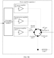
- FIG. 10 is an example diagram of a possible structure of another power amplifier apparatus 1 according to an embodiment of this application.
- the power amplifier apparatus 1 shown in FIG. 10 may be the power amplifier apparatus 1 shown in FIG. 2A .
- the power amplifier apparatus 1 includes M power amplifier units and a circulator unit 4, and the M power amplifier units are connected to the circulator unit 4.
- M is an integer greater than 1, and M may be 2, or may be greater than 2.
- the M power amplifier units include a first power amplifier unit 2 and a second power amplifier unit 3 is used for illustration.
- the circulator unit 4 includes a first port 41, a second port 42, a third port 43, and a fourth port 44.
- An output port of the second power amplifier unit 3 is connected to the second port 42.
- the fourth port 44 of the circulator unit 4 is selectively connected to a load 7 or a third power amplifier unit 8 by using a first switch 6.
- An output port of the first power amplifier unit 2 is selectively connected to the first port 41 of the circulator unit 4 or an input port of a second power amplifier unit 3 by using a second switch 12.
- FIG. 10 It may also be understood as that, in comparison with the foregoing solution in FIG. 3A , a difference in FIG. 10 lies in that the first power amplifier unit 2 in FIG. 10 is not directly connected to the first port 41 of the circulator unit 4, but is connected to the first port 41 and the input port of the second power amplifier unit 3 by using the second switch.
- FIG. 11 is an example diagram of a possible structure of another power amplifier apparatus 1 according to an embodiment of this application.
- FIG. 11 may be considered as an extended embodiment of FIG. 10 .
- the power amplifier apparatus 1 may include a control unit 14 connected to a second switch 12.
- the power amplifier apparatus 1 includes a second signal decomposition module 13.
- An output port of the second signal decomposition module 13 is connected to an input port of the first power amplifier unit 2.
- the second signal decomposition module 13 is configured to divide a received radio frequency signal into K1 channels of signals, and input the signals in the K1 channels of signals into input ports of K1 power amplifier subunits of the first power amplifier unit 2.
- K1 is an integer greater than 1. In FIG. 12A , an example in which a value of K1 is 2 is used for illustration.
- the power amplifier apparatus 1 includes a third signal decomposition module 14.
- An output port of the first power amplifier unit 2 is selectively connected to a first port 41 or an input port of the third signal decomposition module 14 by using a second switch.
- An output port of the third signal decomposition module 14 is connected to an input port of the second power amplifier unit 3.
- any power amplifier unit in the solution shown in FIG. 12A may be any power amplifier unit that is more efficient in FIG. 7A, FIG. 7B , or FIG. 7C .
- a back-off amount of the power amplifier apparatus 1 can be further increased, and back-off efficiency can be improved.
- any power amplifier unit in FIG. 13 may include one or more power amplifiers.
- any power amplifier unit in the power amplifier apparatus 1 in FIG. 13 may be the power amplifier unit in any one of FIG. 7A, FIG. 7B , or FIG. 7C .
- the circulator unit 4 in FIG. 13 may include one or more circulators.
- the circulator unit 4 in FIG. 13 may be the circulator unit in any one of FIG. 8A, FIG. 8B , or FIG. 8C .
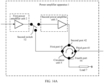
- FIG. 14A and FIG. 14B are example diagrams of several other possible structures of a power amplifier apparatus 1 according to embodiments of this application.
- the power amplifier apparatus 1 shown in FIG. 14A and FIG. 14B may be the power amplifier apparatus 1 shown in FIG. 2B . It can be learned from FIG. 2B that the power amplifier apparatus 1 provided in embodiments of this application may not need to have a function of implementing switching between a radio frequency transmit channel and a radio frequency receive channel. Therefore, in comparison with FIG.
- an embodiment of this application provides a remote radio unit (remote radio unit, RRU).
- the RRU may include the power amplifier apparatus in any one of embodiments shown in FIG. 3A, FIG. 3B , FIG. 3C , FIG. 5A , FIG. 6A , FIG. 7A, FIG. 7B , FIG. 7C , FIG. 7D , FIG. 8A, FIG. 8B , FIG. 8C , FIG. 9A , FIG. 9B , FIG. 9C , FIG. 10 , FIG. 11 , FIG. 12A , FIG. 13 , FIG. 14A , and FIG. 14B .
- an embodiment of this application provides a base station, including the power amplifier apparatus in any one of embodiments shown in FIG. 3A, FIG. 3B , FIG. 3C , FIG. 5A , FIG. 6A , FIG. 7A, FIG. 7B , FIG. 7C , FIG. 7D , FIG. 8A, FIG. 8B , FIG. 8C , FIG. 9A , FIG. 9B , FIG. 9C , FIG. 10 , FIG. 11 , FIG. 12A , FIG. 13 , FIG. 14A , and FIG. 14B .
- an embodiment of this application provides a communication system, including a baseband processing unit, at least one power amplifier apparatus in any one of embodiments shown in FIG. 3A, FIG. 3B , FIG. 3C , FIG. 5A , FIG. 6A , FIG. 7A, FIG. 7B , FIG. 7C , FIG. 7D , FIG. 8A, FIG. 8B , FIG. 8C , FIG. 9A , FIG. 9B , FIG. 9C , FIG. 10 , FIG. 11 , FIG. 12A , FIG. 13 , FIG. 14A , and FIG. 14B connected to the baseband processing unit, and an antenna connected to the third port of the circulator unit in the power amplifier apparatus.
- connection in this application describes a connection relationship between two objects, and may represent two connection relationships.
- a connection between A and B may represent two cases: A is directly connected to B, and A is connected to B through C.
- terms such as “first” and “second” are merely used for distinguishing and description, but should not be understood as indicating or implying relative importance, or should not be understood as indicating or implying a sequence.
- the system structure and the service scenario provided in embodiments of this application are mainly intended to explain some possible implementations of the technical solutions of this application, and should not be construed as a unique limitation on the technical solutions of this application.
- a person of ordinary skill in the art may know that, with evolution of a system and emergence of an updated service scenario, the technical solutions provided in this application are also applicable to a same or similar technical problem.
Landscapes
- Engineering & Computer Science (AREA)
- Power Engineering (AREA)
- Computer Networks & Wireless Communication (AREA)
- Signal Processing (AREA)
- Microelectronics & Electronic Packaging (AREA)
- Amplifiers (AREA)
Applications Claiming Priority (1)
| Application Number | Priority Date | Filing Date | Title |
|---|---|---|---|
| PCT/CN2022/109493 WO2024026629A1 (zh) | 2022-08-01 | 2022-08-01 | 一种功率放大装置、射频拉远单元、基站以及通信系统 |
Publications (2)
| Publication Number | Publication Date |
|---|---|
| EP4535657A1 true EP4535657A1 (de) | 2025-04-09 |
| EP4535657A4 EP4535657A4 (de) | 2025-07-30 |
Family
ID=89848284
Family Applications (1)
| Application Number | Title | Priority Date | Filing Date |
|---|---|---|---|
| EP22953444.1A Pending EP4535657A4 (de) | 2022-08-01 | 2022-08-01 | Leistungsverstärkungsvorrichtung, fernfunkeinheit, basisstation und kommunikationssystem |
Country Status (3)
| Country | Link |
|---|---|
| EP (1) | EP4535657A4 (de) |
| CN (1) | CN119137859A (de) |
| WO (1) | WO2024026629A1 (de) |
Family Cites Families (8)
| Publication number | Priority date | Publication date | Assignee | Title |
|---|---|---|---|---|
| US8542768B2 (en) * | 2009-12-21 | 2013-09-24 | Dali Systems Co. Ltd. | High efficiency, remotely reconfigurable remote radio head unit system and method for wireless communications |
| WO2019119436A1 (zh) * | 2017-12-22 | 2019-06-27 | 华为技术有限公司 | 一种信号处理电路、射频信号发射机和通信设备 |
| EP3821536B1 (de) * | 2018-08-16 | 2023-06-07 | Huawei Technologies Co., Ltd. | Hochfrequenz-frontend für einen vollduplex- oder halbduplex-sender-empfänger |
| DE102019000324A1 (de) * | 2019-01-20 | 2020-07-23 | IAD Gesellschaft für Informatik, Automatisierung und Datenverarbeitung mbH | Sende- und Empfangsvorrichtung mit einem Breitband HF-Leistungsverstärker, insbesondere N-Wege-Doherty Verstärker mit aktiver Lastmodulation |
| WO2022058061A1 (en) * | 2020-09-17 | 2022-03-24 | Nokia Technologies Oy | Energy efficient amplification for an apparatus |
| CN114650016A (zh) * | 2020-12-17 | 2022-06-21 | 中兴通讯股份有限公司 | 功率放大装置、射频拉远单元及基站 |
| CN114024507B (zh) * | 2022-01-10 | 2022-07-01 | 荣耀终端有限公司 | 功率放大电路、射频前端电路、电子设备及信号放大方法 |
| CN114499575B (zh) * | 2022-01-21 | 2024-03-05 | 维沃移动通信有限公司 | 射频功率放大器、模组、电子设备、信号处理方法及装置 |
-
2022
- 2022-08-01 WO PCT/CN2022/109493 patent/WO2024026629A1/zh not_active Ceased
- 2022-08-01 CN CN202280095679.XA patent/CN119137859A/zh active Pending
- 2022-08-01 EP EP22953444.1A patent/EP4535657A4/de active Pending
Also Published As
| Publication number | Publication date |
|---|---|
| CN119137859A (zh) | 2024-12-13 |
| WO2024026629A1 (zh) | 2024-02-08 |
| EP4535657A4 (de) | 2025-07-30 |
Similar Documents
| Publication | Publication Date | Title |
|---|---|---|
| US11502646B2 (en) | Quadrature combined Doherty amplifiers | |
| US6750707B2 (en) | Multi-carrier RF amplifiers | |
| US10819383B2 (en) | Transceivers and methods for operating transceivers | |
| CN111566940B (zh) | 一种信号处理电路、射频信号发射机和通信设备 | |
| US20240079998A1 (en) | Combiners for doherty power amplifier systems | |
| CN114915272A (zh) | 负载调制的多尔蒂功率放大器 | |
| US20150381217A1 (en) | High efficiency, remotely reconfigurable remote radio head unit system and method for wireless communications | |
| US20150340996A1 (en) | Power amplifier, transceiver, and base station | |
| US20240080005A1 (en) | Doherty power amplifier systems with envelope controlled state | |
| TWI400877B (zh) | 具有可重新組態之直流耦合的功率放大器 | |
| US20250080055A1 (en) | Asymmetric doherty power amplifiers | |
| JP7174078B2 (ja) | 非同期tddマルチ帯域動作のための無線ユニット | |
| US11870538B2 (en) | Amplifier networks in a repeater | |
| EP4583470A1 (de) | Leistungsverstärkervorrichtung, fernfunkeinheit und basisstation | |
| WO2022110230A1 (zh) | 一种射频电路、信号反馈电路和通信系统 | |
| WO2024026629A1 (zh) | 一种功率放大装置、射频拉远单元、基站以及通信系统 | |
| EP3602778B1 (de) | Mehrkanaliger doherty-verstärker, mehrantennensender und verfahren zum einschalten des mehrkanaligen doherty-verstärkers | |
| US20250132731A1 (en) | Doherty power amplifier and electronic device including the same | |
| US20250253873A1 (en) | Radio frequency power amplifier, remote radio unit, and base station | |
| WO2024054801A1 (en) | Apparatus and methods for doherty power amplifier systems | |
| EP1054507A2 (de) | Mobile Station mit asymetrischer Nutzung eines Differenzleistungsverstärkers für reduzierte Ausgangsleistung | |
| Li et al. | Silicon based power amplifiers for 4G/5G handset applications | |
| HK40079413A (en) | Load modulated doherty power amplifiers | |
| WO2026061276A1 (zh) | 功放设备、射频拉远单元以及基站 | |
| CN119382629A (zh) | 一种功率放大系统、射频发射系统及信号发射装置 |
Legal Events
| Date | Code | Title | Description |
|---|---|---|---|
| STAA | Information on the status of an ep patent application or granted ep patent |
Free format text: STATUS: THE INTERNATIONAL PUBLICATION HAS BEEN MADE |
|
| PUAI | Public reference made under article 153(3) epc to a published international application that has entered the european phase |
Free format text: ORIGINAL CODE: 0009012 |
|
| STAA | Information on the status of an ep patent application or granted ep patent |
Free format text: STATUS: REQUEST FOR EXAMINATION WAS MADE |
|
| 17P | Request for examination filed |
Effective date: 20250103 |
|
| AK | Designated contracting states |
Kind code of ref document: A1 Designated state(s): AL AT BE BG CH CY CZ DE DK EE ES FI FR GB GR HR HU IE IS IT LI LT LU LV MC MK MT NL NO PL PT RO RS SE SI SK SM TR |
|
| REG | Reference to a national code |
Ref country code: DE Ref legal event code: R079 Free format text: PREVIOUS MAIN CLASS: H03F0001020000 Ipc: H04B0001040000 |
|
| A4 | Supplementary search report drawn up and despatched |
Effective date: 20250702 |
|
| RIC1 | Information provided on ipc code assigned before grant |
Ipc: H04B 1/04 20060101AFI20250626BHEP Ipc: H03F 1/02 20060101ALI20250626BHEP Ipc: H03F 1/32 20060101ALI20250626BHEP Ipc: H04B 1/401 20150101ALI20250626BHEP |
|
| DAV | Request for validation of the european patent (deleted) | ||
| DAX | Request for extension of the european patent (deleted) |