EP4535683A1 - Verfahren und vorrichtung zur csi-messung und -meldung für strahlbetrieb in einem drahtloskommunikationssystem - Google Patents
Verfahren und vorrichtung zur csi-messung und -meldung für strahlbetrieb in einem drahtloskommunikationssystem Download PDFInfo
- Publication number
- EP4535683A1 EP4535683A1 EP23835756.0A EP23835756A EP4535683A1 EP 4535683 A1 EP4535683 A1 EP 4535683A1 EP 23835756 A EP23835756 A EP 23835756A EP 4535683 A1 EP4535683 A1 EP 4535683A1
- Authority
- EP
- European Patent Office
- Prior art keywords
- user equipment
- csi
- base station
- pusch
- transmission
- Prior art date
- Legal status (The legal status is an assumption and is not a legal conclusion. Google has not performed a legal analysis and makes no representation as to the accuracy of the status listed.)
- Pending
Links
Images









Classifications
-
- H—ELECTRICITY
- H04—ELECTRIC COMMUNICATION TECHNIQUE
- H04B—TRANSMISSION
- H04B7/00—Radio transmission systems, i.e. using radiation field
- H04B7/02—Diversity systems; Multi-antenna system, i.e. transmission or reception using multiple antennas
- H04B7/04—Diversity systems; Multi-antenna system, i.e. transmission or reception using multiple antennas using two or more spaced independent antennas
- H04B7/06—Diversity systems; Multi-antenna system, i.e. transmission or reception using multiple antennas using two or more spaced independent antennas at the transmitting station
- H04B7/0613—Diversity systems; Multi-antenna system, i.e. transmission or reception using multiple antennas using two or more spaced independent antennas at the transmitting station using simultaneous transmission
- H04B7/0615—Diversity systems; Multi-antenna system, i.e. transmission or reception using multiple antennas using two or more spaced independent antennas at the transmitting station using simultaneous transmission of weighted versions of same signal
- H04B7/0619—Diversity systems; Multi-antenna system, i.e. transmission or reception using multiple antennas using two or more spaced independent antennas at the transmitting station using simultaneous transmission of weighted versions of same signal using feedback from receiving side
- H04B7/0621—Feedback content
- H04B7/0626—Channel coefficients, e.g. channel state information [CSI]
-
- H—ELECTRICITY
- H04—ELECTRIC COMMUNICATION TECHNIQUE
- H04B—TRANSMISSION
- H04B17/00—Monitoring; Testing
- H04B17/30—Monitoring; Testing of propagation channels
- H04B17/309—Measuring or estimating channel quality parameters
- H04B17/318—Received signal strength
- H04B17/328—Reference signal received power [RSRP]; Reference signal received quality [RSRQ]
-
- H—ELECTRICITY
- H04—ELECTRIC COMMUNICATION TECHNIQUE
- H04B—TRANSMISSION
- H04B17/00—Monitoring; Testing
- H04B17/30—Monitoring; Testing of propagation channels
- H04B17/373—Predicting channel quality or other radio frequency [RF] parameters
-
- H—ELECTRICITY
- H04—ELECTRIC COMMUNICATION TECHNIQUE
- H04B—TRANSMISSION
- H04B7/00—Radio transmission systems, i.e. using radiation field
- H04B7/02—Diversity systems; Multi-antenna system, i.e. transmission or reception using multiple antennas
- H04B7/04—Diversity systems; Multi-antenna system, i.e. transmission or reception using multiple antennas using two or more spaced independent antennas
- H04B7/0408—Diversity systems; Multi-antenna system, i.e. transmission or reception using multiple antennas using two or more spaced independent antennas using two or more beams, i.e. beam diversity
-
- H—ELECTRICITY
- H04—ELECTRIC COMMUNICATION TECHNIQUE
- H04B—TRANSMISSION
- H04B7/00—Radio transmission systems, i.e. using radiation field
- H04B7/02—Diversity systems; Multi-antenna system, i.e. transmission or reception using multiple antennas
- H04B7/04—Diversity systems; Multi-antenna system, i.e. transmission or reception using multiple antennas using two or more spaced independent antennas
- H04B7/06—Diversity systems; Multi-antenna system, i.e. transmission or reception using multiple antennas using two or more spaced independent antennas at the transmitting station
- H04B7/0613—Diversity systems; Multi-antenna system, i.e. transmission or reception using multiple antennas using two or more spaced independent antennas at the transmitting station using simultaneous transmission
- H04B7/0615—Diversity systems; Multi-antenna system, i.e. transmission or reception using multiple antennas using two or more spaced independent antennas at the transmitting station using simultaneous transmission of weighted versions of same signal
- H04B7/0619—Diversity systems; Multi-antenna system, i.e. transmission or reception using multiple antennas using two or more spaced independent antennas at the transmitting station using simultaneous transmission of weighted versions of same signal using feedback from receiving side
- H04B7/0621—Feedback content
- H04B7/0628—Diversity capabilities
-
- H—ELECTRICITY
- H04—ELECTRIC COMMUNICATION TECHNIQUE
- H04B—TRANSMISSION
- H04B7/00—Radio transmission systems, i.e. using radiation field
- H04B7/02—Diversity systems; Multi-antenna system, i.e. transmission or reception using multiple antennas
- H04B7/04—Diversity systems; Multi-antenna system, i.e. transmission or reception using multiple antennas using two or more spaced independent antennas
- H04B7/06—Diversity systems; Multi-antenna system, i.e. transmission or reception using multiple antennas using two or more spaced independent antennas at the transmitting station
- H04B7/0613—Diversity systems; Multi-antenna system, i.e. transmission or reception using multiple antennas using two or more spaced independent antennas at the transmitting station using simultaneous transmission
- H04B7/0615—Diversity systems; Multi-antenna system, i.e. transmission or reception using multiple antennas using two or more spaced independent antennas at the transmitting station using simultaneous transmission of weighted versions of same signal
- H04B7/0619—Diversity systems; Multi-antenna system, i.e. transmission or reception using multiple antennas using two or more spaced independent antennas at the transmitting station using simultaneous transmission of weighted versions of same signal using feedback from receiving side
- H04B7/0636—Feedback format
- H04B7/0639—Using selective indices, e.g. of a codebook, e.g. pre-distortion matrix index [PMI] or for beam selection
-
- H—ELECTRICITY
- H04—ELECTRIC COMMUNICATION TECHNIQUE
- H04B—TRANSMISSION
- H04B7/00—Radio transmission systems, i.e. using radiation field
- H04B7/02—Diversity systems; Multi-antenna system, i.e. transmission or reception using multiple antennas
- H04B7/04—Diversity systems; Multi-antenna system, i.e. transmission or reception using multiple antennas using two or more spaced independent antennas
- H04B7/06—Diversity systems; Multi-antenna system, i.e. transmission or reception using multiple antennas using two or more spaced independent antennas at the transmitting station
- H04B7/0686—Hybrid systems, i.e. switching and simultaneous transmission
- H04B7/0695—Hybrid systems, i.e. switching and simultaneous transmission using beam selection
- H04B7/06952—Selecting one or more beams from a plurality of beams, e.g. beam training, management or sweeping
-
- H—ELECTRICITY
- H04—ELECTRIC COMMUNICATION TECHNIQUE
- H04L—TRANSMISSION OF DIGITAL INFORMATION, e.g. TELEGRAPHIC COMMUNICATION
- H04L5/00—Arrangements affording multiple use of the transmission path
-
- H—ELECTRICITY
- H04—ELECTRIC COMMUNICATION TECHNIQUE
- H04L—TRANSMISSION OF DIGITAL INFORMATION, e.g. TELEGRAPHIC COMMUNICATION
- H04L5/00—Arrangements affording multiple use of the transmission path
- H04L5/003—Arrangements for allocating sub-channels of the transmission path
- H04L5/0048—Allocation of pilot signals, i.e. of signals known to the receiver
-
- H—ELECTRICITY
- H04—ELECTRIC COMMUNICATION TECHNIQUE
- H04L—TRANSMISSION OF DIGITAL INFORMATION, e.g. TELEGRAPHIC COMMUNICATION
- H04L5/00—Arrangements affording multiple use of the transmission path
- H04L5/003—Arrangements for allocating sub-channels of the transmission path
- H04L5/0053—Allocation of signalling, i.e. of overhead other than pilot signals
-
- H—ELECTRICITY
- H04—ELECTRIC COMMUNICATION TECHNIQUE
- H04W—WIRELESS COMMUNICATION NETWORKS
- H04W24/00—Supervisory, monitoring or testing arrangements
- H04W24/08—Testing, supervising or monitoring using real traffic
-
- H—ELECTRICITY
- H04—ELECTRIC COMMUNICATION TECHNIQUE
- H04W—WIRELESS COMMUNICATION NETWORKS
- H04W72/00—Local resource management
- H04W72/12—Wireless traffic scheduling
- H04W72/1263—Mapping of traffic onto schedule, e.g. scheduled allocation or multiplexing of flows
- H04W72/1268—Mapping of traffic onto schedule, e.g. scheduled allocation or multiplexing of flows of uplink data flows
-
- H—ELECTRICITY
- H04—ELECTRIC COMMUNICATION TECHNIQUE
- H04W—WIRELESS COMMUNICATION NETWORKS
- H04W72/00—Local resource management
- H04W72/20—Control channels or signalling for resource management
- H04W72/23—Control channels or signalling for resource management in the downlink direction of a wireless link, i.e. towards a terminal
-
- H—ELECTRICITY
- H04—ELECTRIC COMMUNICATION TECHNIQUE
- H04W—WIRELESS COMMUNICATION NETWORKS
- H04W8/00—Network data management
- H04W8/22—Processing or transfer of terminal data, e.g. status or physical capabilities
- H04W8/24—Transfer of terminal data
Definitions
- the present disclosure relates to a method and apparatus for measuring and reporting CSI for beam operation in a wireless communication system.
- 5G mobile communication technologies define broad frequency bands such that high transmission rates and new services are possible, and can be implemented not only in “Sub 6GHz” bands such as 3.5GHz, but also in “Above 6GHz” bands referred to as mmWave including 28GHz and 39GHz.
- 6G mobile communication technologies referred to as Beyond 5G systems
- terahertz bands for example, 95GHz to 3THz bands
- IIoT Industrial Internet of Things
- IAB Integrated Access and Backhaul
- DAPS Dual Active Protocol Stack
- 5G baseline architecture for example, service based architecture or service based interface
- NFV Network Functions Virtualization
- SDN Software-Defined Networking
- MEC Mobile Edge Computing
- multi-antenna transmission technologies such as Full Dimensional MIMO (FD-MIMO), array antennas and large-scale antennas, metamaterial-based lenses and antennas for improving coverage of terahertz band signals, high-dimensional space multiplexing technology using OAM (Orbital Angular Momentum), and RIS (Reconfigurable Intelligent Surface), but also full-duplex technology for increasing frequency efficiency of 6G mobile communication technologies and improving system networks, AI-based communication technology for implementing system optimization by utilizing satellites and AI (Artificial Intelligence) from the design stage and internalizing end-to-end AI support functions, and next generation distributed computing technology for implementing services at levels of complexity exceeding the limit of UE operation capability by utilizing ultra-high-performance communication and computing resources.
- FD-MIMO Full Dimensional MIMO
- OAM Organic Angular Momentum
- RIS Reconfigurable Intelligent Surface
- the present disclosure relates to a method and apparatus for measuring and reporting channel state information (CSI) for beam operation in a wireless communication system.
- CSI channel state information
- the present disclosure provides a method for receiving a CSI reference signal (CSI-RS) of a user equipment in a wireless communication system and a method for reporting a measured CSI.
- CSI-RS CSI reference signal
- beam operation may be performed equivalent to a system in which the existing CSI-RS is not reduced.
- a user equipment (UE) of a wireless communication system may comprise a transceiving unit; and a control unit configured to: transmit, to a base station, UE capability information regarding a predictable beam of the user equipment; receive channel state information (CSI) configuration information from the base station; receive, from the base station, a reference signal transmitted on the basis of a first transmission beam; acquire CSI related to a second transmission beam predicted on the basis of measurement of the reference signal; and transmit, to the base station, the CSI related to the second transmission beam.
- CSI channel state information
- a base station of a wireless communication system may comprise a transceiving unit; and a control unit configured to: receive, from a user equipment, UE capability information regarding a predictable beam of the user equipment; transmit channel state information (CSI) configuration information to the user equipment; transmit, to a user equipment, a reference signal on the basis of a first transmission beam; and receive, from the user equipment, the CSI related to the second transmission beam that is predicted on the basis of a measurement of the reference signal.
- CSI channel state information
- a method performed by a user equipment of a wireless communication system may comprise: transmitting, to a base station, UE capability information regarding a predictable beam of the user equipment; receiving, from the base station, channel state information (CSI) configuration information; receiving, from the base station, a reference signal transmitted on the basis of a first transmission beam; acquiring CSI related to a second transmission beam predicted on the basis of a measurement of the reference signal; and transmitting, to the base station, the CSI related to the second transmission beam.
- CSI channel state information
- a method performed by a base station of a wireless communication system may comprise: receiving, from a user equipment, UE capability information regarding a predictable beam of the user equipment; transmitting, to the user equipment, channel state information (CSI) configuration information; transmitting, to the user equipment, a reference signal on the basis of a first transmitted beam; and receiving, from the user equipment, the CSI related to a second transmitted beam that is predicted on the basis of a measurement of the reference signal.
- CSI channel state information
- the present disclosure it is possible to reduce the amount of CSI-RS required for a beamforming scheme providing high beamforming gain in a wireless communication system and maintain high quality beam reception sensitivity, thereby increasing data rates as well as providing highly reliable services.
- the base station is the entity that performs resource allocation for the user equipment and may be at least one of gNode B, eNode B, Node B, BS (Base Station), wireless access unit, base station controller, or node on the network.
- a user equipment may include a UE (User Equipment), MS (Mobile Station), a cellular phone, a smartphone, a computer, or a multimedia system capable of performing communication functions.
- DL downlink
- MS Mobile Station
- UL uplink
- UL refers to a wireless transmission path of a signal transmitted from a user equipment to a base station.
- LTE, LTE-A or 5G system may be described below as an example, embodiments of the present disclosure may also be applied to other communication systems with similar technical background or channel type.
- this may include the 5th generation mobile communication technology (5G, new radio, NR) developed after LTE-A, and the term 5G hereinafter may also include the existing LTE, LTE-A, and other similar services.
- 5G new radio
- this disclosure may be applied to other communication systems through some modifications without significantly departing from the scope of the present disclosure at the discretion of a person with skilled technical knowledge.
- each block of the processing flowchart illustrations and combinations of the flowchart illustrations may be performed by computer program instructions.
- These computer program instructions may be mounted on a processor of a general purpose computer, a special purpose computer, or other programmable data processing equipment, such that the instructions, when executed by the processor of the computer or other programmable data processing equipment, create means for performing the functions described in the flowchart block(s).
- These computer program instructions may be stored in computer-usable or computer-readable memory that may be directed to a computer or other programmable data processing equipment to implement the functions in a specific manner, so that the instructions stored in the computer-usable or computer-readable memory may produce a manufactured item comprising instructional means for performing the functions described in the flowchart block(s).
- the computer program instructions may also be mounted on a computer or other programmable data processing equipment and a series of operational steps are performed on the computer or other programmable data processing equipment to create a computer-executable process, such that the instructions performing the computer or other programmable data processing equipment may also provide steps for performing the functions described in the flowchart block(s).
- each block may represent a module, a segment, or a portion of code comprising one or more executable instructions for performing a specified logical function(s).
- the functions recited in the blocks may occur out of sequence. For example, two blocks shown one after the other may in fact be performed substantially simultaneously, or the blocks may be performed in reverse order according to the functions they sometimes perform.
- ' ⁇ unit' used in the present embodiment refers to software or a hardware component such as an FPGA (Field Programmable Gate Array) or ASIC (Application Specific Integrated Circuit), which may perform any of the roles.
- ' ⁇ unit' is not software or hardware specific. It may be configured to reside on an addressable storage medium, or it may be configured to execute one or more processors. Therefore, in one example, ' ⁇ unit' includes components such as software components, object-oriented software components, class components, and task components, processes, functions, properties, procedures, subroutines, segments of program code, drivers, firmware, microcode, circuits, data, databases, data structures, tables, arrays, and variables.
- the functionality provided within the components and ' ⁇ units' may be combined into fewer components and ' ⁇ units', or further separated into additional components and ' ⁇ units'. Furthermore, the components and ' ⁇ units' may be implemented to play one or more CPUs within the device or the security multimedia card.
- Wireless communication systems have evolved from providing initially voice-oriented services to broadband wireless communication systems that provide high-speed, high-quality packet data services, for example, using communication standards such as 3GPP's High Speed Packet Access (HSPA), Long Term Evolution (LTE) or Evolved Universal Terrestrial Radio Access (E-UTRA), LTE-Advanced (LTE-A), LTE-Pro, 3GPP2's High Rate Packet Data (HRPD), Ultra Mobile Broadband (UMB), and IEEE's 802.16e.
- HSPA High Speed Packet Access
- LTE Long Term Evolution
- E-UTRA Evolved Universal Terrestrial Radio Access
- LTE-A LTE-Advanced
- LTE-Pro LTE-Pro
- HRPD High Rate Packet Data
- UMB Ultra Mobile Broadband
- IEEE's 802.16e IEEE's 802.16e.
- the LTE system adopts the OFDM (Orthogonal Frequency Division Multiplexing) method for the downlink (DL) and the SC-FDMA (Single Carrier Frequency Division Multiple Access) method for the uplink (UL).
- Uplink refers to a wireless link in which a user equipment (UE (User Equipment) or MS (Mobile Station)) transmits data or control signals to a base station (eNode B, or base station (BS)), and downlink refers to a wireless link in which a base station transmits data or control signals to a user equipment.
- the data or control information of each user may be distinguished by allocating and operating the time-frequency resources to carry data or control information for each user so that they do not overlap, i.e., orthogonality is established.
- the 5G communication system should be able to freely reflect various requirements of users and service providers, so services that satisfy various requirements simultaneously should be supported.
- the services considered for 5G communication systems include enhanced Mobile Broadband (eMBB), massive Machine Type Communication (mMTC), and Ultra Reliability Low Latency Communication (URLLC).
- eMBB enhanced Mobile Broadband
- mMTC massive Machine Type Communication
- URLLC Ultra Reliability Low Latency Communication
- eMBB aims to provide higher data rates than those supported by conventional LTE, LTE-A, or LTE-Pro.
- eMBB should be able to provide a peak data rate of 20 Gbps in the downlink and 10 Gbps in the uplink from the perspective of one base station.
- 5G communication systems must provide peak data rates while also providing increased user perceived data rates.
- various transmission and reception technologies will need to be improved, including more advanced multi-antenna (Multi Input Multi Output, MIMO) transmission technologies.
- MIMO Multi Input Multi Output
- 5G communication systems will use wider frequency bandwidths than 20 MHz in the 3-6 GHz or 6 GHz or higher frequency bands to meet the data rates required by 5G communication systems.
- mMTC is being considered to support application services such as the Internet of Things (IoT) in 5G communication systems.
- IoT Internet of Things
- mMTC needs to support the access of a large number of user equipments within a cell, improve coverage of user equipments, improve battery life, and reduce the cost of user equipments. Since the Internet of Things will be attached to multiple sensors and various devices to provide communication capabilities, it must be able to support a large number of user equipments (e.g., 1,000,000 user equipments/km2) within a cell.
- mMTC-enabled user equipments are likely to be located in shadowed areas that are not covered by cells, such as the basement of a building, and may require greater coverage than other services provided by 5G communication systems.
- the mMTC-enabled devices will need to be low-cost devices and may require very long battery life times, such as 10 to 15 years, as it is difficult to replace the device's battery frequently.
- URLLC is a cellular-based wireless communication service used for specific mission-critical purposes. Examples include services used for remote control of robots or machinery, industrial automation, unmanned aerial vehicles, remote health care, emergency alerts, etc. As such, the communication provided by URLLC must be extremely low latency and highly reliable. For example, services that support URLLC must satisfy an air interface latency of less than 0.5 milliseconds, while simultaneously having a packet error rate requirement of 75 or less. Therefore, for services supporting URLLC, the 5G system may need to provide a smaller Transmit Time Interval (TTI) than other services, and at the same time, the design may require a large resource allocation in the frequency band to ensure the reliability of the communication link.
- TTI Transmit Time Interval
- the three services of 5G may be multiplexed and transmitted in one system.
- different transmission and reception techniques and transmission and reception parameters may be used among the services to satisfy the different requirements of each service.
- 5G is not limited to the above three services.
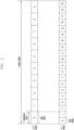
- FIG. 1 is a diagram illustrating the basic structure of the time-frequency domain, which is a radio resource domain where data or control channels are transmitted in a 5G wireless communication system.
- the horizontal axis represents the time domain
- the vertical axis represents the frequency domain.
- the basic unit of resources in the time and frequency domains is a Resource Element (RE) 101, which is defined as 1 OFDM (Orthogonal Frequency Division Multiplexing) symbol 102 on the time axis and 1 subcarrier 103 on the frequency axis.
- RE Resource Element
- N sc RB for example, 12
- consecutive REs may constitute one Resource Block (RB) 104.
- FIG. 2 is a diagram illustrating an example of a slot structure used in a 5G wireless communication system.
- 1 frame 200 may be defined as 10ms.
- 1 subframe 201 may be defined as 1 ms, and therefore 1 frame 200 may consist of a total of 10 subframes 201.
- 1 subframe 201 may consist of one or a plurality of slots 202 and 203, and the number of slots 202 and 203 per 1 subframe 201 may vary depending on the configuration value ⁇ 204 and 205 for the subcarrier spacing.
- FIG. 1 frame 200 may be defined as 10ms.
- 1 subframe 201 may be defined as 1 ms, and therefore 1 frame 200 may consist of a total of 10 subframes 201.
- 1 subframe 201 may consist of one or a plurality of slots 202 and
- N slot frame , ⁇ according to each subcarrier spacing configuration ⁇ may be defined as [Table 1] below. [Table 1] ⁇ N symb slot N slot frame , ⁇ N slot subframe , ⁇ 0 14 10 1 1 14 20 2 2 14 40 4 3 14 80 8 4 14 160 16 5 14 320 32
- BWP Bandwidth Part
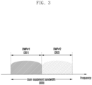
- FIG. 3 is a diagram illustrating an example of configurations for a bandwidth part (BWP) in a 5G wireless communication system.
- BWP bandwidth part
- the UE bandwidth 300 is configured to two bandwidth parts, that is, bandwidth part #1 (BWP#1) 301 and bandwidth part #2 (BWP#2) 302.
- the base station may configure one or more bandwidth parts to the user equipment and may configure the following information for each bandwidth part.
- the configurations for the bandwidth part are not limited to the above examples, and various parameters related to the bandwidth part may be configured to the user equipment in addition to the above configuration information.
- the configuration information may be transmitted by the base station to the user equipment through higher layer signaling, e.g., Radio Resource Control (RRC) signaling.
- RRC Radio Resource Control
- At least one bandwidth part of the configured one or more bandwidth parts may be activated.
- the activation status for a configured bandwidth part may be semi-statically transmitted from the base station to the user equipment through RRC signaling or dynamically transmitted through Downlink Control Information (DCI).
- DCI Downlink Control Information
- the user equipment prior to the Radio Resource Control (RRC) connection may receive the Initial Bandwidth Part (Initial BWP) for the initial connection from the base station through the Master Information Block (MIB). More specifically, during the initial connection phase, the user equipment may receive configuration information for the Control Resource Set (CORESET) and the search space in which a PDCCH may be transmitted to receive the system information required for the initial connection (which may correspond to Remaining System Information (RMSI) or System Information Block 1 (SIB1)) through the MIB.
- the control resource set and search space configured by the MIB may be regarded as Identity (ID) 0, respectively.
- the base station may notify the user equipment of configuration information such as frequency allocation information, time allocation information, and numerology for control resource set #0 through the MIB.
- the base station may notify the user equipment of the monitoring period and occasion for the control resource set #0 through the MIB, that is, the configuration information for the search space #0.
- the user equipment may regard the frequency domain configured in the control resource set #0 obtained from the MIB as the initial bandwidth part for the initial connection.
- the identity (ID) of the initial bandwidth part may be regarded as 0.
- the configuration for the bandwidth part supported by the 5G wireless communication system may be used for various purposes.
- the configuration for the bandwidth part may be used when the bandwidth supported by the user equipment is smaller than the system bandwidth.
- the base station may configure the frequency location of the bandwidth part (configuration information 2) to the user equipment, allowing the user equipment to transmit and receive data at a specific frequency location within the system bandwidth.
- the base station may configure a plurality of bandwidth parts to the user equipment for the purpose of supporting different numerologies. For example, to support both data transmission and reception using a subcarrier spacing of 15kHz and a subcarrier spacing of 30kHz for a user equipment, the base station may configure the two bandwidth parts to the subcarrier spacing of 15kHz and 30kHz, respectively. Different bandwidth parts may be frequency division multiplexed, and when the base station wants to transmit and receive data at a specific subcarrier interval, the bandwidth part configured at the corresponding subcarrier interval may be activated.
- the base station may configure bandwidth parts with bandwidths of different sizes to the user equipment. For example, if the user equipment supports a very large bandwidth, for example, 100 MHz, and always transmits and receives data through that bandwidth, very large power consumption may occur. In particular, monitoring unnecessary downlink control channels with a large bandwidth of 100 MHz in a situation where there is no traffic may be very inefficient in terms of power consumption.
- the base station may configure a relatively small bandwidth part, for example, a bandwidth part of 20 MHz, to the user equipment. In a situation where there is no traffic, the user equipment may perform monitoring operations in the 20 MHz bandwidth part, and when data is generated, it may transmit and receive data in the 100 MHz bandwidth part according to the instructions of the base station.
- user equipments before RRC connection may receive configuration information regarding the Initial Bandwidth Part through Master Information Block (MIB) in the initial connection stage.
- MIB Master Information Block
- the user equipment may have a Control Resource Set (CORESET) be configured for the downlink control channel through which Downlink Control Information (DCI) scheduling System Information Block (SIB) may be transmitted from the MIB of Physical Broadcast Channel (PBCH).
- DCI Downlink Control Information
- SIB System Information Block
- PBCH Physical Broadcast Channel
- the bandwidth of the Control Resource Set configured as MIB may be regarded as the initial bandwidth part, and through the configured initial bandwidth part, the user equipment may receive Physical Downlink Shared Channel (PDSCH) on which the SIB is transmitted.
- PDSCH Physical Downlink Shared Channel
- the initial bandwidth part may also be used for Other System Information (OSI), Paging, and Random Access.
- OSI System Information
- the base station may instruct the user equipment to change the bandwidth part using the bandwidth part indicator field in the DCI. For example, in FIG. 3 , if the currently activated bandwidth part of the user equipment is bandwidth part #1 301, the base station may instruct the user equipment to use the bandwidth part indicator in the DCI to indicate bandwidth part #2 302, and the user equipment may perform a bandwidth part switch to bandwidth part #2 302 as indicated by the bandwidth part indicator in the received DCI.
- the DCI based bandwidth part switch may be directed by the DCI scheduling the PDSCH or PUSCH, the user equipment shall be able to receive or transmit the PDSCH or PUSCH scheduled by that DCI in the switched bandwidth part without any difficulty when it receives the bandwidth part switch request.
- T BWP time delay
- the standard specifies requirements for the required time delay (T BWP) for a bandwidth part switch, which may be defined, for example, as follows. [Table 3] ⁇ NR Slot length (ms) BWP switch delay T BWP (slots) Type 1 Note 1 Type 2 Note 1 0 1 [1] [3] 1 0.5 [2] [5] 2 0.25 [3] [9] 3 0.125 [6] [17] Note 1: Depends on UE capability. Note 2: If the BWP switch involves changing of SCS, the BWP switch delay is determined by the larger one between the SCS before BWP switch and the SCS after BWP switch.
- Requirements for bandwidth part switch delay time may support type 1 or type 2 depending on the UE capability.
- the user equipment may report the supportable bandwidth part delay time type to the base station.
- the user equipment when the user equipment receives a DCI including a bandwidth part change indicator in slot n, the user equipment may complete the change to the new bandwidth part indicated by the bandwidth part change indicator at a time not later than slot n+ T BWP , and may perform transmission and reception on the data channel scheduled by the DCI in the new bandwidth part.
- the base station may determine the time domain resource allocation for the data channel by considering the bandwidth part change delay time (T BWP ) of the user equipment. That is, when the base station schedules a data channel with a new bandwidth part, the base station may schedule the data channel after the bandwidth part change delay time in determining the time domain resource allocation for the data channel. Accordingly, the user equipment may not expect a DCI indicating a bandwidth part change to indicate a slot offset (K0 or K2) value that is less than the bandwidth part change delay time (T BWP ).
- T BWP bandwidth part change delay time
- the user equipment may not perform any transmissions or receptions during the time interval from the third symbol of the slot in which it received the PDCCH including that DCI to the beginning of the slot indicated by the slot offset (K0 or K2) value indicated by the time domain resource allocation indicator field within that DCI. For example, if a user equipment receives a DCI instructing a bandwidth part change in slot n, and the slot offset value indicated by that DCI is K, the user equipment may not perform any transmissions or receptions from the third symbol of slot n until the symbol before slot n+K (i.e., the last symbol of slot n+K-1).
- a DCI e.g., DCI format 1_1 or 0_1
- SS/PBCH block may refer to a physical layer channel block consisting of primary SS (PSS), secondary SS (SSS), and PBCH. Specifically, it may be as follows.
- the user equipment may detect PSS and SSS in the initial access stage and decode the PBCH.
- the MIB may be obtained from the PBCH, and a control resource set (CORE SET) #0 (which may correspond to a control resource set with a control resource set index of 0) may be configured from this.
- the user equipment may perform monitoring on control resource set #0 assuming that the selected SS/PBCH block and the Demodulation Reference Signal (DMRS) transmitted in control resource set #0 are in Quasi Co Location (QCL).
- DMRS Demodulation Reference Signal
- the user equipment may receive system information through downlink control information transmitted from control resource set #0.
- the user equipment may obtain Random Access Channel (RACH) related configuration information necessary for initial access from the received system information.
- RACH Random Access Channel
- the user equipment may transmit Physical RACH (PRACH) to the base station in consideration of the SS/PBCH index selected, and the base station receiving the PRACH may obtain information about the SS/PBCH block index selected by the user equipment.
- PRACH Physical RACH
- the base station may know which block the user equipment has selected among each SS/PBCH block and monitor the control resource set #0 related to it.
- DCI Downlink Control Information
- scheduling information for uplink data may be transmitted from the base station to the user equipment through DCI.
- the user equipment may monitor a fallback DCI format and a non-fallback DCI format for PUSCH or PDSCH.
- the fallback DCI format may consist of fixed fields that are predetermined between the base station and the user equipment, while the non-fallback DCI format may include configurable fields.
- DCI may be transmitted through the Physical Downlink Control Channel (PDCCH) after channel coding and modulation.
- a Cyclic Redundancy Check (CRC) is attached to the DCI message payload and the CRC may be scrambled with a Radio Network Temporary Identifier (RNTI) corresponding to the identity of the user equipment.
- RNTI Radio Network Temporary Identifier
- Different RNTIs may be used depending on the purpose of the DCI message, e.g., for UE-specific data transmission, power control commands or random access responses. That is, the RNTI is not transmitted explicitly but is included in the CRC calculation.
- the user equipment receives a DCI message transmitted on the PDCCH, it checks the CRC using the assigned RNTI and if the CRC check result is correct, the user equipment knows that the message has been transmitted to the user equipment.
- the DCI that schedules PDSCHs for System Information may be scrambled with SI-RNTI.
- the DCI that schedules PDSCHs for Random Access Response (RAR) messages may be scrambled with RA-RNTI.
- the DCI that schedules PDSCHs for paging messages may be scrambled with P-RNTI.
- the DCI that notifies the Slot Format Indicator (SFI) may be scrambled with the SFI-RNTI.
- the DCI that notifies the Transmit Power Control (TPC) may be scrambled with the TPC-RNTI.
- the DCIs that schedule UE-specific PDSCHs or PUSCHs may be scrambled with Cell RNTI (C-RNTI), Modulation Coding Scheme C-RNTI (MCS-C-RNTI), or Configured Scheduling RNTI (CS-RNTI).
- C-RNTI Cell RNTI
- MCS-C-RNTI Modulation Coding Scheme C-RNTI
- CS-RNTI Configured Scheduling RNTI
- DCI format 0_0 may be used as a fallback DCI for scheduling PUSCH, where the CRC may be scrambled with C-RNTI.
- DCI format 0_0 with the CRC scrambled with the C-RNTI may include, for example, the following information.
- DCI format 0_1 may be used as a non-fallback DCI for scheduling PUSCH, where the CRC may be scrambled with C-RNTI.
- DCI format 0_1 with the CRC scrambled with the C-RNTI may include, for example, the following information.
- DCI format 1_0 may be used as a fallback DCI for scheduling PDSCH, where the CRC may be scrambled with C-RNTI.
- DCI format 1_0 with the CRC scrambled with C-RNTI may include, for example, the following information.
- [Table 6] - Identifier for DCI formats - 1 bits - The value of this bit field is always set to 1, indicating a DL DCI format - Frequency domain resource assignment - log 2 N RB DL , BWP N RB DL , BWP + 1 / 2 bits where N RB DL , BWP is given by subclause 7.3.1.0 If the CRC of the DCI format 1_0 is scrambled by C-RNTI and the "Frequency domain resource assignment" field are of all ones, the DCI format 1_0 is for random access procedure initiated by a PDCCH order, with all remaining fields set as follows: - Random Access Preamble index - 6 bits according to ra-Preamblelndex in Subclause 5.1.2 of [8, TS38.321] - UL/SUL indicator - 1 bit.
- this field indicates which UL carrier in the cell to transmit the PRACH according to Table 7.3.1.1.1-1; otherwise, this field is reserved - SS/PBCH index - 6 bits. If the value of the "Random Access Preamble index” is not all zeros, this field indicates the SS/PBCH that shall be used to determine the RACH occasion for the PRACH transmission; otherwise, this field is reserved. - PRACH Mask index - 4 bits.
- this field indicates the RACH occasion associated with the SS/PBCH indicated by "SS/PBCH index” for the PRACH transmission, according to Subclause 5.1.1 of [8, TS38.321]; otherwise, this field is reserved - Reserved bits - 10 bits Otherwise, all remaining fields are set as follows: - Time domain resource assignment - 4 bits as defined in Subclause 5.1.2.1 of [6, TS 38.214] - VRB-to-PRB mapping -1 bit according to Table 7.3.1.2.2-5 - Modulation and coding scheme - 5 bits as defined in Subclause 5.1.3 of [6, TS 38.214] - New data indicator - 1 bit - Redundancy version - 2 bits as defined in Table 7.3.1.1.1-2 - HARQ process number - 4 bits - Downlink assignment index - 2 bits as defined in Subclause 9.1.3 of [5, TS 38.213], as counter DAI - TPC command for scheduled PUCCH
- DCI format 1_1 may be used as a non-fallback DCI for scheduling PDSCH, where the CRC may be scrambled with C-RNTI.
- DCI format 1_1 with the CRC scrambled with the C-RNTI may include, for example, the following information.
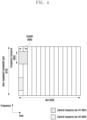
- FIG. 4 is a diagram illustrating an example of a Control Resource Set (CORESET) through which a downlink control channel is transmitted in a 5G wireless communication system.
- CORESET Control Resource Set
- the UE bandwidth part 410 may be configured on the frequency axis, and two control resource sets (control resource set #1 401, control resource set #2 402) may be configured within one slot 420 on the time axis.
- the control resource sets 401 and 402 may be configured to specific frequency resources 403 within the overall UE bandwidth part 410 on the frequency axis.
- the control resource sets 401 and 402 may be configured to one or more OFDM symbols on the time axis, which may be defined as a Control Resource Set Duration 404.
- control resource set #1 401 is configured to a control resource set duration of 2 symbols
- control resource set #2 402 is configured to a control resource set duration of 1 symbol.
- the control resource set may be configured by the base station to the user equipment through higher layer signaling (e.g., System Information, Master Information Block (MIB), Radio Resource Control (RRC) signaling).
- Configuring a control resource set to a user equipment means providing information such as the control resource set identity, the frequency location of the control resource set, and the symbol length of the control resource set.
- the information may include the following.
- the tci-StatesPDCCH (simply named Transmission Configuration Indication (TCI) state) configuration information may include information of one or more Synchronization Signal (SS)/Physical Broadcast Channel (PBCH) Block indices or Channel State Information Reference Signal (CSI-RS) indices that are in a Quasi Co Location (QCL) relationship with the DMRS transmitted by the corresponding control resource set.
- TCI Transmission Configuration Indication
- SS Synchronization Signal
- PBCH Physical Broadcast Channel
- CSI-RS Channel State Information Reference Signal
- FIG. 5 is a diagram illustrating the structure of a downlink control channel in a 5G wireless communication system.
- FIG. 5 is a diagram illustrating an example of the basic units of time and frequency resources that constitute a downlink control channel that may be used in a 5G wireless communication system.
- the basic unit of time and frequency resources constituting a control channel may be a Resource Element Group (REG) 503, wherein the REG 503 may be defined by 1 OFDM symbol 501 on the time axis and 1 Physical Resource Block (PRB) 502 on the frequency axis, i.e., 12 subcarriers.
- the base station can configure a downlink control channel allocation unit by concatenating REGs 503.
- one CCE 504 may consist of a plurality of REGs 503.
- the REG 503 may consist of 12 REs, and if one CCE 504 consists of six REG 503s, then one CCE 504 may consist of 72 REs.
- the corresponding area may consist of a plurality of CCEs 504, and a particular downlink control channel may be mapped to one or more CCEs 504 for transmission on the basis of an Aggregation Level (AL) within the control resource set.
- A Aggregation Level
- the CCEs 504 within the control resource set may be numbered, wherein the CCEs 504 may be numbered according to a logical mapping method.
- the basic unit of the downlink control channel shown in FIG. 5 may include both REs to which DCIs are mapped and areas to which DMRSs 505, which are reference signals for decoding them, are mapped. As shown in FIG. 5 , three DMRSs 505 may be transmitted within one REG 503.
- a search space representing the set of CCEs is defined for blind decoding.
- a search space is a set of downlink control channel candidates consisting of CCEs that the user equipment must attempt to decode at a given aggregation level, and since there are several aggregation levels that create bundles of 1, 2, 4, 8, and 16 CCEs, a user equipment may have multiple search spaces.
- a search space set may be defined as the set of search spaces at all configured aggregation levels.
- the search space may be categorized into common search space and UE-specific search space.
- the common search space of the PDCCH may be searched by a certain group of user equipments or all user equipments to receive cell common control information such as dynamic scheduling or paging messages for system information. For example, PDSCH scheduling allocation information for the transmission of SIBs including the cell's operator information, etc. may be received by searching the common search space of the PDCCH.
- the common search space may be defined as the set of CCEs that are pre-defined because a certain group of user equipments or all user equipments should receive the PDCCH. Scheduling assignment information for a UE-specific PDSCH or PUSCH may be received by searching the UE-specific search space of the PDCCH.
- the UE-specific search space may be defined UE-specifically as a function of the identity of the user equipment and various system parameters.
- parameters for the search space for the PDCCH may be configured from the base station to the user equipment by higher layer signaling (e.g., SIB, MIB, RRC signaling).
- the base station may configure to the user equipment the number of PDCCH candidates at each aggregation level L, the monitoring period for the search space, the monitoring occasion per symbol in the slot for the search space, the type of search space (common search space or UE-specific search space), the combination of DCI format and RNTI to be monitored in the search space, and the control resource set index to monitor the search space.
- the parameters for a search space for a PDCCH may include the following information.
- the base station may configure one or more search space sets to the user equipment.
- the base station may configure a search space set 1 and a search space set 2 for the user equipment, and may configure DCI format A scrambled with X-RNTI in search space set 1 to be monitored in a common search space, and may configure DCI format B scrambled with Y-RNTI in search space set 2 to be monitored in a UE-specific search space.
- one or more sets of search spaces may exist in the common search space or the UE-specific search space.
- search space set #1 and search space set #2 may be configured as the common search spaces
- search space set #3 and search space set #4 may be configured as the UE-specific search spaces.
- the combination of the following DCI format and RNTI may be monitored.
- this is not limited to the following examples.
- the combination of the following DCI format and RNTI may be monitored.
- this is not limited to the following examples.
- the specified RNTIs may have the following definitions and uses.
- the search space of the aggregation level L in the control resource set p and the search space set s may be expressed as the following equation.
- FIG. 6 is a diagram illustrating an example of uplink-downlink configurations considered in a 5G communication system according to an embodiment of the present disclosure.
- the slot 601 may include 14 symbols 602.
- the uplink-downlink configurations of symbols/slots may be established in three steps. First, on a semi-static, symbol-by-symbol basis, the uplink-downlink of a symbol/slot may be configured semi-statically through cell-specific configuration information 610 through system information in a symbol unit. Specifically, the cell-specific uplink-downlink configuration information through system information may include uplink-downlink pattern information and reference subcarrier information.
- the uplink-downlink pattern information may indicate a pattern periodicity 603 and a consecutive downlink slot number 611 and a symbol number 612 of the next slot from the start of each pattern, and a consecutive uplink slot number 613 and a symbol number 614 of the next slot from the end of the pattern.
- slots and symbols not indicated as uplink slots/symbols 606 or downlink slots/symbols 604 may be determined to be flexible slots/symbols 605.
- the slots 621 and 622 including flexible slots or flexible symbols through user-specific configuration information 620 through dedicated higher layer signaling may be indicated to a consecutive number of downlink symbols 623 and 625 from the beginning symbol of the slot and a consecutive number of uplink symbols 624 and 626 from the end of the slot, respectively, or to a slot-wide downlink or slot-wide uplink.
- the symbols that are indicated as flexible symbols in each slot may be indicated whether they are downlink symbols, uplink symbols, or flexible symbols through Slot Format Indicators (SFIs) 631 and 632 included in the downlink control channel 630.
- the slot format indicator may be selected by a single index from a table of preset uplink-downlink configurations of 14 symbols in a single slot, as shown in Table 11 below.
- one or more different antenna ports may be associated with each other by a Quasi Co Location (QCL) configuration as shown in Table 12 below.
- QCL Quasi Co Location
- the TCI state is intended to announce the QCL relationship between PDCCH (or PDCCH DMRS) and other RSs or channels, and when a reference antenna port A (reference RS #A) and another target antenna port B (target RS #B) are QCLed, it means that the user equipment is allowed to apply some or all of the large-scale channel parameters estimated at antenna port A to the channel measurements from antenna port B.
- the QCL may need to relate different parameters depending on the situation, such as 1) time tracking, which is affected by average delay and delay spread, 2) frequency tracking, which is affected by Doppler shift and Doppler spread, 3) radio resource management (RRM), which is affected by average gain, and 4) beam management (BM), which is affected by spatial parameters. Therefore, NR supports four types of QCL relationships as shown in Table 12 below. [Table 12] QCL type Large-scale characteristics A Doppler shift, Doppler spread, average delay, delay spread B Doppler shift, Doppler spread C Doppler shift, average delay D Spatial Rx parameter
- the spatial RX parameter may refer to any or all of various parameters such as Angle of arrival (AoA), Power Angular Spectrum (PAS) of AoA, Angle of departure (AoD), PAS of AoD, transmit/receive channel correlation, transmit/receive beamforming, spatial channel correlation, etc.
- AoA Angle of arrival
- PAS Power Angular Spectrum
- AoD Angle of departure
- PAS PAS of AoD
- transmit/receive channel correlation transmit/receive beamforming
- spatial channel correlation etc.
- the QCL relationship may be configured to the user equipment through the RRC parameters TCI-State and QCL-Info as shown in Table 13 below.
- the base station may configure one or more TCI states to inform the user equipment of up to two QCL relationships (qcl-Type1, qcl-Type2) for the RS referring to the ID of the TCI state, i.e., the target RS.
- each QCL information (QCL-Info) included in each TCI state includes the serving cell index and BWP index of the reference RS to which the QCL information refers, the type and ID of the reference RS, and the QCL type as shown in Table 13.
- FIG. 7 is a diagram illustrating an example of base station beam allocation according to TCI state configurations.
- the base station may communicate information about different N beams to the user equipment through different N TCI states.
- the base station may communicate that the antenna ports referencing the three TCI states 700, 705, and 710 have different spatial Rx parameters, i.e., different beams, by ensuring that the qcl-Type2 parameters included in the three TCI states 700, 705, and 710 are associated with CSI-RS or SSB corresponding to different beams and are configured to QCL type D.
- Tables 14-1 through 14-5 below show the valid TCI state according to target antenna port type.
- Table 14-1 illustrates valid TCI state configurations when the target antenna port is CSI-RS for tracking (TRS).
- TRS refers to an NZP CSI-RS in which the repetition parameter is not configured, and trs-Info is configured to true among CSI-RSs.
- Configuration number 3 in Table 14-1 may be used for aperiodic TRS.
- Valid TCI state configurations when the target antenna port is CSI-RS for tracking (TRS)
- QCL-TypeD 3 TRS (periodic)
- QCL-TypeA TRS (same as DL RS 1)
- QCL-TypeD QCL-TypeD
- Table 14-2 illustrates valid TCI state configurations when the target antenna port is CSI-RS for CSI.
- the CSI-RS for CSI refers to an NZP CSI-RS in which a parameter indicating repetition (e.g., repetition parameter) is not configured and trs-Info is also not configured to true among CSI-RSs.
- Table 14-3 illustrates valid TCI state configurations when the target antenna port is CSI-RS for beam management (BM, same meaning as CSI-RS for L1 RSRP reporting).
- the CSI-RS for BM refers to an NZP CSI-RS in which the repetition parameter is configured and has a value of On or Off, and trs-Info is not configured to true among CSI-RSs.
- Table 14-4 illustrates valid TCI state configurations when the target antenna port is PDCCH DMRS.
- Valid TCI state configurations when the target antenna port is PDCCH DMRS Valid TCI state Configuration DL RS 1 qcl-Type1 DL RS 2 (if configured) qcl-Type2 (if configured) 1 TRS QCL-TypeA TRS (same as DL RS 1)
- QCL-TypeD 2 TRS QCL-TypeA CSI-RS (BM)
- QCL-TypeA CSI-RS (same as DL RS 1)
- Table 14-5 illustrates valid TCI state configurations when the target antenna port is PDSCH DMRS.
- Valid TCI state configurations when the target antenna port is PDSCH DMRS Valid TCI state Configuration DL RS 1 qcl-Type1 DL RS 2 (if configured) qcl - Type2 (if configured) 1 TRS QCL-TypeA TRS QCL-TypeD 2 TRS QCL-TypeA CSI-RS (BM) QCL-TypeD 3 CSI-RS (CSI) QCL-TypeA CSI-RS (CSI) QCL-TypeD
- the representative QCL configuration method according to the Tables 14-1 to 14-5 is to configure the target antenna port and reference antenna port for each step as "SSB” -> "TRS” -> "CSI-RS for CSI, or CSI-RS for BM, or PDCCH DMRS, or PDSCH DMRS". This allows the statistical features measured from SSB and TRS to be linked to each antenna port to help the reception operation of the user equipment.
- TCI state combinations applicable to the PDCCH DMRS antenna port are shown in Table 15 below.
- the fourth row in Table 15 is the combination assumed by the user equipment before RRC configuration, and configuration after RRC is not possible.
- Table 15 Valid TCI state Configuration DL RS 1 qcl- Type1 DL RS 2 (if configured) qcl-Type2 (if configured) 1 TRS QCL-TypeA TRS QCL-TypeD 2 TRS QCL-TypeA CSI-RS (BM) QCL-TypeD 3 CSI-RS (CSI) QCL-TypeA 4 SS/PBCH Block QCL-TypeA SS/PBCH Block QCL-TypeD
- the NR supports a hierarchical signaling method, as illustrated in FIG. 8 , for dynamic allocation of PDCCH beams.
- the base station may configure N TCI states 805, 810, 815, ..., 820 to the user equipment through RRC signaling 800, some of which may be configured as TCI states for CORESET 825.
- the base station may then indicate one of the TCI states 830, 835, and 840 for CORESET to the user equipment through MAC CE signaling 845.
- the user equipment receives a PDCCH on the basis of beam information that includes the TCI state indicated by the MAC CE signaling.
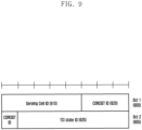
- FIG. 9 is a diagram illustrating a TCI indication MAC CE signaling structure for the PDCCH DMRS.
- the TCI indication MAC CE signaling for the PDCCH DMRS consists of 2 bytes (16 bits) and includes a 5-bit serving cell ID 915, a 4-bit CORESET ID 920, a 7-bit TCI state ID 925.
- FIG. 10 is a diagram illustrating an example of beam configurations of a control resource set (CORESET) and search space according to the above description.
- the base station may indicate one of the TCI state lists included in the CORESET 1000 configuration through MAC CE signaling 1005. Afterwards, until a different TCI state is subsequently indicated to that CORESET through another MAC CE signaling, the user equipment considers that the same QCL information (beam #1) 1005 applies to all of the one or more search spaces 1010, 1015, and 1020 associated with the CORESET.
- the above-described PDCCH beam allocation method has the disadvantage that it is difficult to indicate a beam change faster than the MAC CE signaling delay, and also has the disadvantage that the same beam is applied to all of the CORESETs regardless of the search space features, which makes it difficult to operate flexible PDCCH beams.
- the following embodiments of the present invention provide a more flexible PDCCH beam configuration and operation method.
- several distinct examples are provided for ease of explanation, but they are not mutually exclusive and may be combined with each other as appropriate depending on the situation.
- the base station may configure one or more TCI states for a specific control area to the user equipment and may activate one of the configured TCI states through the MAC CE activation command. For example, if control area #1 has ⁇ TCI state#0, TCI state#1, TCI state#2 ⁇ configured as the TCI state for control area #1, the base station may transmit a command to the user equipment through MAC CE to enable the user equipment to assume TCI state#0 as the TCI state for control area #1. On the basis of the activation command for the TCI state received by the MAC CE, the user equipment may correctly receive DMRS for the corresponding control area on the basis of the QCL information in the activated TCI state.
- control area #0 For the control area (control area #0) with index configured to 0, if the user equipment does not receive a MAC CE activation command for the TCI state of control area #0, the user equipment may assume that the DMRS transmitted from control area #0 is QCL with the SS/PBCH block identified in the initial access process or in the non-contention based random access process that is not triggered by the PDCCH command.
- control area #X For a control area (control area #X) with an index configured to a value other than 0, if the user equipment has not received a TCI state for control area #X, or if it has received one or more TCI states but has not received a MAC CE activation command to activate one of them, the user equipment may assume that it is QCL with the SS/PBCH block identified during the initial connection process for DMRS transmitted from control area #X.
- the user equipment may select a particular control resource set according to the QCL prioritization operation and monitor the control resource sets with the same QCL-TypeD attributes as the corresponding control resource set.
- the criteria for determining QCL priority may be as follows.
- the next criterion shall be applied if the corresponding criterion is not met. For example, if control resource sets overlap in time in a particular PDCCH monitoring interval, and if all control resource sets are connected to a UE-specific search interval and not to a common search interval, i.e., if criterion 1 is not met, the user equipment may omit applying criterion 1 and apply criterion 2.
- the user equipment may additionally consider two points regarding the QCL information configured in the control resource set as follows. First, if control resource set 1 has CSI-RS 1 as a reference signal with a QCL-TypeD relationship, the reference signal with which this CSI-RS 1 has a QCL-TypeD relationship is SSB 1, and another control resource set 2 has a reference signal with which a QCL-TypeD relationship is SSB 1, the user equipment may consider that these two control resource sets 1 and 2 have different QCL-TypeD features.
- control resource set 1 has CSI-RS 1 configured in cell 1 as the reference signal with QCL-TypeD relationship
- the reference signal with which CSI-RS 1 has QCL-TypeD relationship is SSB 1
- control resource set 2 has CSI-RS 2 configured in cell 2 as the reference signal with QCL-TypeD relationship
- the reference signal with which CSI-RS 2 has QCL-TypeD relationship is the same SSB 1
- the user equipment may consider the two control resource sets to have the same QCL-TypeD features.
- FIG. 11 is a diagram illustrating a method for a user equipment to select a set of control resources that can be received in consideration of priority when receiving a downlink control channel in a wireless communication system according to an embodiment of the present disclosure.
- the user equipment may be configured to receive multiple control resource sets (CORESET) that overlap in time in a specific PDCCH monitoring interval 1110, and these multiple control resource sets may be connected to a common search space (CSS) or a UE-specific search space (USS) for multiple cells.
- CRS control resource sets
- USS UE-specific search space
- first control resource set 1115 associated with the first common search space within the first bandwidth part 1100 of cell 1
- first control resource set 1120 associated with the first common search space and a second control resource set 1125 associated with the second UE-specific search space within the first bandwidth part 1105 of cell 2.
- the control resource sets 1115 and 1120 may have a relationship of QCL-TypeD with the CSI-RS resource configured in the first bandwidth part of cell 1
- the control resource set 1125 may have a relationship of QCL-TypeD with the CSI-RS resource configured in the first bandwidth part of cell 2.
- applying criterion 1 for the corresponding PDCCH monitoring interval 1110 allows the user equipment to receive all other control resource sets having the same QCL-TypeD reference signal as control resource set 1115.
- the user equipment may receive control resource sets 1115 and 1120 in the corresponding PDCCH monitoring interval 1110.
- the user equipment may be configured to receive a plurality of temporally overlapping control resource sets in a specific PDCCH monitoring interval 1140, wherein the plurality of control resource sets may be associated with a common search space or a UE-specific search space for the plurality of cells.
- first control resource set 1145 associated with the first UE-specific search space and a second control resource set 1150 associated with the second UE-specific search space within the first bandwidth part 1130 of the first cell
- first control resource set 1155 associated with the first UE-specific search space
- second control resource set 1160 associated with the third UE-specific search space within the first bandwidth part 1135 of the second cell.
- the control resource sets 1145 and 1150 may have a QCL-TypeD relationship with the first CSI-RS resource set within the first bandwidth part of the first cell
- the control resource set 1155 may have a QCL-TypeD relationship with the first CSI-RS resource configured within the first bandwidth part of the second cell
- the control resource set 1160 may have a QCL-TypeD relationship with the second CSI-RS resource configured within the first bandwidth part of the second cell.
- applying criterion 1 to the corresponding PDCCH monitoring interval 1140 shows that there is no common search interval, so the next criterion, criterion 2, may be applied.
- Applying criterion 2 for the corresponding PDCCH monitoring interval 1140 allows the user equipment to receive all other control resource sets that have the same QCL-TypeD reference signal as the control resource set 1145. Therefore, the user equipment may receive control resource sets 1145 and 1150 in the corresponding PDCCH monitoring interval 1140.
- FIG. 12 is a diagram illustrating an example of frequency axis resource allocation of a physical downlink shared channel (PDSCH) in a wireless communication system according to an embodiment of the present disclosure.
- PDSCH physical downlink shared channel
- FIG. 12 is a diagram illustrating three frequency axis resource allocation methods, type 0 12-00, type 1 12-05, and dynamic switch 12-10, that may be configured through the higher layer in an NR wireless communication system.
- NRBG means the number of resource block groups (RBGs) determined by the BWP size assigned by the BWP indicator and the higher layer parameter rbg-Size as shown in Table 16 below, and data is transmitted to the RBGs indicated by 1 in the bitmap.
- RBG resource block groups
- some DCIs that allocate the PDSCH to the user equipment include frequency axis resource allocation information consisting of log 2 N RB DL , BWP N RB DL , BWP + 1 / 2 bits. The conditions for this will be explained later.
- the base station may configure the starting VRB 12-20 and the length 12-25 of the frequency axis resources continuously allocated from it.
- some DCIs that allocate PDSCHs to the corresponding user equipment include frequency axis resource allocation information consisting of bits 12-35 of the greater of payload 12-15 for configuring resource type 0 and payloads 12-20 and 12-25 for configuring resource type 1. The conditions for this will be described later.
- one bit may be added to the most significant bit (MSB) of the frequency axis resource allocation information in the DCI, and if the bit has a value of '0', it indicates that resource type 0 is used, and if the bit has a value of '1', it indicates that resource type 1 is used.
- MSB most significant bit
- the base station may configure a table of time domain resource allocation information for the Physical Downlink Shared Channel (PDSCH) and Physical Uplink Shared Channel (PUSCH) to the user equipment for higher layer signaling (e.g., RRC signaling).
- PDSCH Physical Downlink Shared Channel
- PUSCH Physical Uplink Shared Channel
- Time domain resource allocation information may include, for example, PDCCH-to-PDSCH slot timing (corresponding to the time interval in slots between when a PDCCH is received and when the PDSCH scheduled by the received PDCCH is transmitted, denoted as K0) or PDCCH-to-PUSCH slot timing (corresponding to the time interval in slots between when a PDCCH is received and when the PUSCH scheduled by the received PDCCH is transmitted, denoted as K2), information about the position and length of the start symbol within the slot for which the PDSCH or PUSCH is scheduled, and the mapping type of the PDSCH or PUSCH. For example, information such as [Table 17] and [Table 18] below may be communicated from the base station to the user equipment.
- the base station may notify the user equipment through L1 signaling (e.g., a DCI) of one of the entries in the table for the time domain resource allocation information (e.g., as indicated by the 'time domain resource allocation' field in the DCI).
- the user equipment may obtain the time domain resource allocation information for PDSCH or PUSCH on the basis of the DCI received from the base station.
- the 5G wireless communication system supports two types, resource allocation type 0 and resource allocation type 1, as a method to indicate frequency domain resource allocation information for the Physical Downlink Shared Channel (PDSCH) and Physical Uplink Shared Channel (PUSCH).
- resource allocation type 0 resource allocation type 1
- PDSCH Physical Downlink Shared Channel
- PUSCH Physical Uplink Shared Channel
- the RBG may consist of a set of consecutive Virtual RBs (VRBs), and the size P of the RBG may be determined on the basis of the value configured by the higher layer parameter ( rbg-Size ) and the size value of the bandwidth part defined by the table below.
- rbg-Size the higher layer parameter
- the total number of RBGs ( N RBG ) of bandwidth part i of size N BWP , i size may be defined as follows.
- the base station may configure the resource allocation type through higher layer signaling to the user equipment (e.g., the higher layer parameter resourceAllocation may be configured to one of the values, resourceAllocationType0 or resourceAllocationType1 or dynamicSwitch). If the user equipment has both resource allocation type 0 and 1 configured (or equivalently, if the higher layer parameter resourceAllocation is configured to dynamicSwitch), the base station may indicate whether the bit corresponding to the Most Significant Bit (MSB) of the field indicating the resource allocation in the DCI format indicating scheduling is resource allocation type 0 or resource allocation type 1.
- MSB Most Significant Bit
- the resource allocation information may be indicated through the remaining bits except the bit corresponding to the MSB, and the user equipment may interpret the resource allocation field information in the DCI field on the basis of this. If the user equipment has received either resource allocation type 0 or resource allocation type 1 (or equivalently, if the higher layer parameter resourceAllocation has been configured to one of the values, resourceAllocationType0 or resourceAllocationType1), then the resource allocation information in the field indicating resource allocation in the DCI format indicating scheduling may be indicated on the basis of the indicated resource allocation type, and the user equipment may interpret the resource allocation field information in the DCI field on the basis of the indicated resource allocation type.
- FIG. 13 illustrates the process for beam configuration and activation of PDSCH.
- the list of TCI states for the PDSCH may be indicated through a higher layer list such as the RRC 13-00.
- the list of TCI states may be indicated, for example, as tci-StatesToAddModList and/or tci-StatesToReleaseList in the PDSCH-Config IE for each BWP.
- some of the above list of TCI states may be activated through MAC-CE 13-20.
- some of the TCI states activated through MAC-CE may be selected through DCI 13-40.
- the maximum number of activated TCI states may be determined by the capability reported by the user equipment.
- 13-50 shows an example of a MAC-CE structure for PDSCH TCI state activation/deactivation.
- PUSCH transmission may be dynamically scheduled by the UL grant in DCI or operated by configured grant Type 1 or Type 2. Dynamic scheduling instructions for PUSCH transmission are possible in DCI format 0_0 or 0_1.
- Configured grant Type 1 PUSCH transmissions may be configured semi-statically by the receipt of a configuredGrantConfig including the rrc-ConfiguredUplinkGrant of [Table 20] through higher layer signaling, without the receipt of a UL grant through DCI.
- Configured grant Type 2 PUSCH transmissions may be scheduled semi-persistently by the UL grant in the DCI, following the receipt of a configuredGrantConfig that does not include the rrc-ConfiguredUplinkGrant of [Table 20] through higher layer signaling.
- the parameters applied to the PUSCH transmission may be applied through the configuredGrantConfig in [Table 20] that is received through higher layer signaling, except dataScramblingIdentityPUSCH, txConfig, codebookSubset, maxRank, and scaling of UCI-OnPUSCH, which are provided by the pusch-Config in [Table 21] that is higher layer signaling.
- the user equipment has been provided a transformPrecoder in configuredGrantConfig in [Table 20] through higher layer signaling, the user equipment shall apply tp-pi2BPSK in pusch-Config in [Table 21] for PUSCH transmissions operated by the configured grant.
- the DMRS antenna port for PUSCH transmission is the same as the antenna port for SRS transmission.
- PUSCH transmission may follow a codebook-based transmission method and a non-codebook-based transmission method, respectively, depending on whether the value of txConfig in pusch-Config of [Table 21], which is higher layer signaling, is 'codebook' or 'nonCodebook'.
- PUSCH transmissions may be dynamically scheduled through DCI format 0_0 or 0_1 and may be semi-statically configured by a configured grant. If the user equipment is indicated to schedule a PUSCH transmission through DCI format 0_0, the user equipment performs beam configuration for the PUSCH transmission using the pucch-spatialRelationInfoID corresponding to the UE-specific PUCCH resource corresponding to the minimum ID within the activated uplink BWP in the serving cell, and, in this case, the PUSCH transmission is on the basis of a single antenna port.
- Codebook-based PUSCH transmissions may be dynamically scheduled through DCI format 0_0 or 0_1, or they may be operated semi-statically by the configured grant.
- the user equipment determines the precoder for PUSCH transmission on the basis of the SRS Resource Indicator (SRI), Transmission Precoding Matrix Indicator (TPMI), and transmission rank (number of PUSCH transmission layers).
- SRI SRS Resource Indicator
- TPMI Transmission Precoding Matrix Indicator
- transmission rank number of PUSCH transmission layers.
- the SRI may be given through the field, SRS resource indicator, in the DCI or configured through the higher layer signaling, srs-ResourceIndicator.
- the user equipment may configure at least one SRS resource in a codebook-based PUSCH transmission and may configure up to two. If the user equipment receives an SRI through DCI, the SRS resource indicated by the SRI means the SRS resource corresponding to the SRI among the SRS resources transmitted earlier than the PDCCH including the SRI.
- the TPMI and transmission rank may be given through the field, precoding information and number of layers, in the DCI, or may be configured through the higher layer signaling precodingAndNumberOfLayers.
- the precoder to be used for PUSCH transmission is selected from the uplink codebook with the number of antenna ports equal to the value of nrofSRS-Ports in the higher layer signaling SRS-Config.
- the user equipment determines the codebook subset on the basis of the TPMI and codebookSubset in the higher layer signaling pusch-Config.
- the codebookSubset in the higher layer signaling, pusch-Config may be configured to one of 'fullyAndPartialAndNonCoherent', 'partialAndNonCoherent', or 'nonCoherent' on the basis of the UE capability that the user equipment reports to the base station.
- the user equipment reports 'partialAndNonCoherent' as the UE capability, the user equipment does not expect the value of the higher layer signaling codebookSubset to be configured to 'fullyAndPartialAndNonCoherent'. In addition, if the user equipment reports 'nonCoherent' as UE capability, the user equipment does not expect the value of the higher layer signaling codebookSubset to be configured to 'fullyAndPartialAndNonCoherent' or 'partialAndNonCoherent'.
- nrofSRS-Ports in the higher layer signaling, SRS-ResourceSet points to two SRS antenna ports
- the user equipment does not expect the value of the higher layer signaling, codebookSubset, to be configured to 'partialAndNonCoherent'.
- the user equipment may receive one SRS resource set with the value of usage in the higher layer signaling, SRS-ResourceSet, configured to 'codebook', and one SRS resource within that SRS resource set may be indicated through SRI. If multiple SRS resources are configured within an SRS resource set with the value of usage in the higher layer signaling, SRS-ResourceSet, configured to 'codebook', the user equipment expects the value of nrofSRS-Ports in the higher layer signaling, SRS-Resource, to be configured to the same value for all SRS resources.
- the user equipment transmits to the base station one or more SRS resources included in the SRS resource set with the value of usage configured to 'codebook' according to the higher layer signaling, and the base station selects one of the SRS resources transmitted by the user equipment and indicates the user equipment to perform a PUSCH transmission using the transmission beam information of the SRS resource.
- the SRI is used as the information for selecting the index of the one SRS resource, and the SRI may be included in the DCI.
- the base station includes in the DCI information indicating the TPMI and rank that the user equipment shall use for the PUSCH transmission. The user equipment performs the PUSCH transmission using the SRS resource indicated by the SRI, applying the precoder indicated by the rank and the TPMI indicated by the TPMI on the basis of the transmission beam of the SRS resource.
- Non-codebook based PUSCH transmission may be dynamically scheduled through DCI format 0_0 or 0_1 and may be operated semi-statically by the configured grant. If at least one SRS resource is configured in the SRS resource set with the value of usage in the higher layer signaling, SRS-ResourceSet, configured to 'nonCodebook', the user equipment may receive scheduled non-codebook based PUSCH transmissions through DCI format 0_1.
- the user equipment may receive, through higher layer signaling, the configuration of one NZP CSI-RS resource (non-zero power CSI-RS) associated with the SRS resource set with the value of usage in the SRS-ResourceSet configured to 'nonCodebook'.
- the user equipment may perform the calculation for the precoder for SRS transmission by measuring the NZP CSI-RS resource associated with the SRS resource set. If the difference between the last received symbol of the aperiodic NZP CSI-RS resource associated with the SRS resource set and the first symbol of the aperiodic SRS transmission from the user equipment is less than 42 symbols, the user equipment does not expect the information about the precoder for SRS transmission to be updated.
- the associated NZP CSI-RS is indicated to SRS request, which is a field in DCI format 0_1 or 1_1.
- SRS request is a field in DCI format 0_1 or 1_1.
- the associated NZP CSI-RS resource is an aperiodic NZP CSI-RS resource and the value of the SRS request field in DCI format 0_1 or 1_1 is not '00', it may indicate the existence of an NZP CSI-RS associated with the SRS resource set. In this case, the corresponding DCI shall not indicate cross carrier or cross BWP scheduling.
- the corresponding NZP CSI-RS shall be located in the slot in which the PDCCH including the SRS request field was transmitted.
- the TCI states configured on the scheduled subcarrier shall not be configured to QCL-TypeD.
- the associated NZP CSI-RS may be indicated through the associatedCSI-RS in the higher layer signaling, SRS-ResourceSet.
- the user equipment does not expect the spatialRelationInfo, the higher layer signaling for the SRS resource, and the associatedCSI-RS in the higher layer signaling, SRS-ResourceSet, to be configured together.
- the user equipment may determine the precoder and transmission rank to be applied to the PUSCH transmission on the basis of the SRI indicated by the base station when multiple SRS resources are configured.
- the SRI may be indicated through the SRS resource indicator field in the DCI or configured through the higher layer signaling, srs-ResourceIndicator.
- the SRS resource to which the SRI refers is the SRS resource corresponding to the SRI, among the SRS resources transmitted prior to the PDCCH including the SRI.
- the user equipment may use one or multiple SRS resources for SRS transmission, and the maximum number of SRS resources and the maximum number of simultaneous transmissions on the same symbol within one SRS resource set are determined by the UE capability that the user equipment reports to the base station. In this case, the SRS resources transmitted simultaneously by the user equipment occupy the same RB.
- the user equipment configures one SRS port for each SRS resource. Only one SRS resource configured with the value of usage in the higher layer signaling, SRS-ResourceSet, configured to 'nonCodebook' may be configured, and up to four SRS resources for non-codebook based PUSCH transmission may be configured.
- the base station transmits one NZP-CSI-RS associated with the SRS resource set to the user equipment, and the user equipment calculates the precoder to be used when transmitting one or more SRS resources in the SRS resource set on the basis of the measurement result when receiving the corresponding NZP-CSI-RS.
- the user equipment applies the above calculated precoder when transmitting one or more SRS resources in the SRS resource set whose usage is configured to 'nonCodebook' to the base station, and the base station selects one or more SRS resources among the one or more SRS resources received.
- the SRI represents an index that can represent a combination of the one or more SRS resources, and the SRI is included in the DCI.
- the number of SRS resources indicated by the SRI transmitted by the base station may be the number of transmission layers of the PUSCH, and the user equipment transmits the PUSCH by applying the precoder applied to the SRS resource transmission to each layer.
- the PUSCH preparation procedure time is described.
- the base station schedules the user equipment to transmit PUSCH using DCI format 0_0 or DCI format 0_1
- the user equipment may need PUSCH preparation procedure time to apply the transmission method (transmission precoding method of SRS resource, number of transmission layers, spatial domain transmission filter) indicated through DCI to transmit PUSCH.
- NR has defined the PUSCH preparation procedure time in consideration of this.
- the PUSCH preparation procedure time of a user equipment may be on the basis of [Equation 2] below.
- T proc , 2 max N 2 + d 2 , 1 + d 2 2048 + 144 ⁇ 2 ⁇ ⁇ T c + T ext + T switch , d 2 , 2
- each variable may have the following meaning.
- N 2 Number of symbols determined by UE processing capability 1 or 2 and numerology ⁇ , depending on the capability of the user equipment. Depending on the capability reporting of the user equipment, it may have a value of [Table 22] if it is reported as UE processing capability 1, or a value of [Table 23] if it is reported as UE processing capability 2 and it is configured through higher layer signaling that UE processing capability 2 is available. [Table 22] ⁇ PUSCH preparation time N 2 [symbols] 0 10 1 12 2 23 3 36 [Table 23] ⁇ PUSCH preparation time N 2 [symbols] 0 5 1 5.5 2 11 for frequency range 1
- the base station and the user equipment determines that the PUSCH preparation procedure time is insufficient if the first symbol of the PUSCH starts before the first uplink symbol initiated by the CP after T proc,2 from the last symbol of the PDCCH including the DCI that scheduled the PUSCH, considering the time axis resource mapping information of the PUSCH scheduled through the DCI and the uplink-downlink timing advance (TA) impact. Otherwise, the base station and the user equipment determines that the PUSCH preparation procedure time is sufficient. The user equipment transmits the PUSCH only if the PUSCH preparation procedure time is sufficient and may ignore the DCI scheduling the PUSCH if the PUSCH preparation procedure time is insufficient.
- TA uplink-downlink timing advance
- PUSCH repeat transmission is described.
- a user equipment is scheduled for a PUSCH transmission with DCI format 0_1 in a PDCCH including a CRC scrambled with C-RNTI, MCS-C-RNTI, or CS-RNTI, and the user equipment configures a higher layer signaling, pusch-AggregationFactor, the same symbol allocation is applied in consecutive slots equal to the pusch-AggregationFactor, and the PUSCH transmission is limited to a single rank transmission.
- the user equipment must repeat the same TB in as many consecutive slots as pusch-AggregationFactor, with the same symbol allocation for each slot.
- [Table 24] illustrates the redundancy version to be applied for PUSCH repeat transmissions for each slot. If the user equipment has scheduled PUSCH repeat transmissions in multiple slots in DCI format 0_1, and at least one of the symbols in the slots in which the PUSCH repeat transmissions are to occur is indicated as a downlink symbol according to the information in the higher layer signaling, tdd-UL-DL-ConfigurationCommon or tdd-UL-DL-ConfigurationDedicated, the user equipment does not perform PUSCH transmissions in the slot in which the symbol is located.
- the 5G system supports two types of repeat transmission methods for the uplink data channel, PUSCH repetition type A and PUSCH repetition type B.
- the user equipment may be configured to either PUSCH repetition type A or B by higher layer signaling.
- the user equipment may consider symbols other than the invalid symbol as valid symbols. If at least one valid symbol is included in each nominal repetition, the nominal repetition may include one or more actual repetitions. Here, each actual repetition includes a consecutive set of valid symbols that may be used for a PUSCH repetition type B within one slot. If the OFDM symbol length of the nominal repetition is not one, the user equipment may ignore the transmission for that actual repetition if the length of the actual repetition becomes one.
- FIG. 14 illustrates an example of PUSCH repetition type B according to an embodiment of the present disclosure.
- FIG. 14 illustrates an example in which the user equipment receives a transmission start symbol S configured to 0, a length L of the transmission symbol configured to 10, and the number of repeat transmissions configured to 10 for a nominal repetition 1402, which may be represented by N1 to N10 in the drawing.
- the user equipment may determine the actual repetition 1403 by determining the invalid symbol in consideration of the slot format 1401, and may be represented by A1 to A10 in the drawing.
- PUSCH repetition type B is not transmitted in a symbol whose slot format is determined as a downlink (DL), and if a slot boundary exists within the nominal repetition, the nominal repetition may be divided into two actual repetitions on the basis of the slot boundary and be transmitted.
- A1 the first actual repetition may consist of three OFDM symbols
- A2, which may be transmitted next may consist of six OFDM symbols.
- NR Release 16 may define the following additional methods for UL grant-based PUSCH transmission and configured grant-based PUSCH transmission across slot boundaries.
- rate matching for uplink control information (UCI) in the 5G system will be described in detail.
- UCI uplink control information
- the user equipment may multiplex the HARQ-ACK and/or CSI information included in PUCCH into the PUSCH and may not transmit PUCCH according to the UCI information included in PUSCH.
- timeline conditions for UCI multiplexing may refer to 3GPP standard TS 38.213 clause 9.2.5.
- UCI multiplexing if either PUCCH transmission or PUSCH transmission is scheduled through DCI, the user equipment transmits the earliest PUCCH or PUSCH among the PUCCH and PUSCH overlapping in the slot.
- UCI multiplexing may be performed only if the symbol S 0 satisfies the following conditions:
- the user equipment may perform UCI multiplexing on PUSCH.
- UCI multiplexing is performed in the following order: HARQ-ACK, configured grant uplink control information (CG-UCI), CSI part 1, and CSI part 2.
- CG-UCI uplink control information
- CSI part 1 CSI part 2
- the user equipment performs rate matching considering the UCI multiplexing order. Therefore, the user equipment calculates the coded modulation symbol per layer for HARQ-ACK and CG-UCI and considers this to calculate the coded modulation symbol per layer of CSI part 1. Afterwards, the user equipment calculates the coded modulation symbol per layer of CSI part 2 by considering the coded modulation symbol per layer for HARQ-ACK, CG-UCI, and CSI part 1.
- the method for calculating the number of coded modulation symbols per layer is different depending on the type of repeat transmission of the PUSCH on which the UCI is multiplexed and whether or not uplink data (uplink shared channel, hereinafter UL-SCH) is included.
- uplink data uplink shared channel, hereinafter UL-SCH
- the calculation formula for the number of coded modulation symbols per layer depending on the PUSCH over which the UCI is multiplexed are as follows.
- [Equation 3] is the coded modulation symbol calculation formula per layer for HARQ-ACK multiplexed on the PUSCH when the PUSCH including UL-SCH is not a repetition type B
- [Equation 4] is the formula for calculating the coded modulation symbol per layer for the PUSCH including the UL-SCH. This is the coded modulation symbol calculation formula per layer for HARQ-ACK multiplexed in the repetition transmission type B
- [Equation 5] is the coded modulation symbol calculation formula per layer for HARQ-ACK multiplexed to PUSCH that does not include UL-SCH.
- O ACK is the number of HARQ-ACK bits.
- L ACK is the number of CRC bits for HARQ-ACK.
- ⁇ offset PUSCH is the beta offset for HARQ-ACK and is equal to C UL-SCH is the number of code blocks of UL-SCH for PUSCH transmission, and K r is the code block size of the r-th code block.
- C UL-SCH is the number of code blocks of UL-SCH for PUSCH transmission
- K r is the code block size of the r-th code block.
- ⁇ is higher layer parameter scaling, which means the ratio of resources on which UCI may be multiplexed among all resources for PUSCH transmission.
- l o represents the index of the first symbol that does not include the DMRS after the first DMRS.
- Equation 4 represents the number of resource elements that may be used for UCI transmission for nominal repetition, is 0 for symbols including DMRS, and is equal to for symbols not including DMRS, and is the number of subcarriers including PTRS in the symbol l for PUSCH assuming nominal repetition. means the total number of symbols for the nominal repetition of PUSCH.
- R is the code rate of the PUSCH and Q m is the modulation order of the PUSCH.
- the number of coded modulation symbols per layer with rate matching of CSI part 1 may be calculated similarly to HARQ-ACK, but the number of resources that may be allocated to the maximum of the total resources is reduced to the value excluding the number of coded modulation symbols for HARQ-ACK/CG-UCI.
- the calculation formula for coded modulation symbols per layer in CSI part 1 is as follows: [Equation 6], [Equation 7], [Equation 8], and [Equation 9] depending on the repetition type of PUSCH and whether UL-SCH is included or not.
- [Equation 6] is the coded modulation symbol calculation formula per layer for CSI part 1 multiplexed to the PUSCH in the case of non-PUSCH repetition type B including the UL-SCH
- [Equation 7] is the formula for calculating the coded modulation symbol per layer for the PUSCH including the UL-SCH. This is the coded modulation symbol calculation formula per layer for CSI part 1 multiplexed in repetition type B.
- [Equation 8] is the coded modulation symbol calculation formula per layer for the multiplexed CSI part 1 when CSI part 1 and CSI part 2 are multiplexed in the PUSCH that does not include the UL-SCH.
- [Equation 9] is the coded modulation symbol calculation formula per layer for CSI part 1 that is multiplexed when CSI part 2 is not multiplexed in PUSCH that does not include UL-SCH.
- O CSI- 1 and L CSI- 1 mean the number of bits for CSI part 1 and the number of CRC bits for CSI part 1, respectively.
- ⁇ offset PUSCH is the beta offset for CSI part 1 and is equal to ⁇ offset CSI ⁇ part 1 .
- Q ' ACK / CG-UCI is the number of coded modulation symbols per layer calculated for HARQ-ACK and/or CG-UCI. Other parameters are the same as those required to calculate the number of coded modulation symbols per layer for HARQ-ACK.
- the number of coded modulation symbols per layer with rate matching of CSI part 2 may be calculated similarly to CSI part 1, but the maximum number of resources that can be allocated among the total resources is reduced to the value excluding the number of coded modulation symbols for HARQ-ACK/CG-UCI and the number of coded modulation symbols for CSI part 2.
- the calculation equations for coded modulation symbols per layer in CSI part 1 are as follows: [Equation 10], [Equation 11], and [Equation 12] depending on the repetition type of PUSCH and whether UL-SCH is included or not.
- [Equation 10] is the coded modulation symbol calculation formula per layer for CSI part 2 multiplexed to the PUSCH when the PUSCH including the UL-SCH is not repetition type B
- [Equation 11] is the formula for calculating the coded modulation symbol per layer for the PUSCH including the UL-SCH. This is the coded modulation symbol calculation formula per layer for CSI part 2 multiplexed in repetition type B
- [Equation 12] is the coded modulation symbol calculation formula per layer for CSI part 2 multiplexed to PUSCH that does not include UL-SCH.
- O CSI -2 and L CSI -2 mean the number of bits for CSI part 2 and the number of CRC bits for CSI part 2, respectively.
- ⁇ offset PUSCH is the beta offset for CSI part 2 and is equal to Other parameters are the same as those required to calculate the number of coded modulation symbols per layer for HARQ-ACK and CSI part 1.
- the number of coded modulation symbols per layer that performed rate matching of CG-UCI may also be calculated similarly to HARQ-ACK.
- the calculation formula for the coded modulation symbol per layer of CG-UCI multiplexed to the PUSCH including the UL-SCH is as in [Equation 13].
- O CG-UCI , and L CG-UCI mean the number of bits of CG-UCI and the number of CRC bits for CG-UCI, respectively.
- ⁇ offset PUSCH is the beta offset for CG-UCI and is equal to ⁇ offset CG ⁇ UCI .
- Other parameters are the same as those required to calculate the number of coded modulation symbols per layer for HARQ-ACK.
- the number of coded modulation symbols per layer that performed rate matching of H ARQ- ACK and CG-UCI may be calculated as in [Equation 14].
- ⁇ offset PUSCH is the beta offset for HARQ-ACK and is equal to ⁇ offset HARQ ⁇ ACK , and other parameters are the same as the parameters required to calculate the number of coded modulation symbols per layer for HARQ-ACK.
- Channel state information may include channel quality information (CQI), precoding matrix indicator (PMI), CSI-RS resource indicator (CRI), and synchronization signa /physical broadcast channel (SS/PBCH) block resource indicator (SSBRI), layer indicator (LI), rank indicator (RI), and/or L1-Reference Signal Received Power (RSRP), etc.
- the base station may control time and frequency resources for CSI measurement and reporting of the user equipment.
- the user equipment may receive at least one of the configuration information CSI-ReportConfig for N ( ⁇ 1) CSI reports, the configuration information CSI-ResourceConfig for M ( ⁇ 1) RS transmission resources, and the trigger status lists CSI- At least one of AperiodicTriggerStateList and CSI-SemiPersistentOnPUSCH-TriggerStateList through higher layer signaling.
- Configuration information for the above-described CSI measurement and reporting may be more specifically as described in Tables 25 to 31 below.
- Each reporting configuration CSI-ReportConfig may be associated with one downlink (DL) bandwidth part, identified by the bandwidth part identity bwp-Id, which is a higher layer parameter given by the CSI resource configuration CSI-ResourceConfig associated with the corresponding reporting configuration.
- Time domain reporting for each reporting configuration CSI-ReportConfig supports an 'aperiodic', 'semi-persistent' or 'periodic' method, which may be configured from the base station to the user equipment by the higher layer parameter reportConfigType.
- the semi-persistent CSI reporting method supports semi-persistent reporting on PUCCH, which is configured by semi-PersistentOnPUCCH, and semi-persistent reporting on PUSCH, which is configured by semi-PersistentOnPUSCH .
- the user equipment may receive the PUCCH resource or PUSCH resource to transmit CSI from the base station through higher layer signaling.
- the periodicity and slot offset to transmit the CSI may be given by the numerology of the uplink (UL) bandwidth part on which the CSI report is configured to be transmitted.
- the user equipment may receive scheduling of PUSCH resources to transmit CSI from the base station through L1 signaling (e.g., DCI format 0_1).
- each CSI resource configuration CSI-ReportConfig may include S( ⁇ 1) CSI resource sets (given by the higher layer parameter csi-RS-ResourceSetList ).
- the CSI resource set list may consist of a non-zero power (NZP) CSI-RS resource set and an SS/PBCH block set, or a CSI interference measurement (CSI-IM) resource set.
- NZP non-zero power
- CSI-IM CSI interference measurement
- Each CSI resource configuration may be located in a downlink (DL) bandwidth part identified by the higher layer parameter bwp-Id, and the CSI resource configuration may be associated with the CSI reporting configuration of the same downlink bandwidth part.
- the time domain operation of the CSI-RS resource within the CSI resource configuration may be configured to one of 'aperiodic', 'periodic', or 'semi-permanent' from the higher layer parameter resourceType .
- the user equipment may receive one or more CSI resource configurations for channel or interference measurement through higher layer signaling from the base station.
- the CSI resource configurations may include at least one of the following resources.
- the trigger state for CSI reporting configurations with reportType configured to 'aperiodic' and the resource configuration for channel or interference measurement for one or multiple component cells (CC) may be configured to the higher layer parameter CSI-AperiodicTriggerStateList .
- Aperiodic CSI reporting of the user equipment may use PUSCH, periodic CSI reporting may use PUCCH, and semi-permanent CSI reporting may be performed using PUSCH when triggered or activated by DCI and using PUCCH after activated by MAC control elements (MAC CE).
- PUSCH PUSCH
- periodic CSI reporting may use PUCCH
- semi-permanent CSI reporting may be performed using PUSCH when triggered or activated by DCI and using PUCCH after activated by MAC control elements (MAC CE).
- MAC CE MAC control elements
- CSI resource configurations may also be configured aperiodically, periodically, or semi-permanently.
- the combination between CSI reporting configurations and CSI resource configurations may be on the basis of Table 32 below. [Table 32] Triggering/Activation of CSI Reporting for the possible CS I-RS Configurations.
- the UE For reporting on PUCCH, the UE receives an activation command [10, TS 38.321]; for reporting on PUSCH, the UE receives triggering on DCI Triggered by DCI; additionally, activation command [10, TS 38.321] possible as defined in Subclause 5.2.1.5.1.
- the UE receives an activation command [10, TS 38.321]; for reporting on PUSCH, the UE receives triggering on DCI Triggered by DCI; additionally, activation command [10, TS 38.321] possible as defined in Subclause 5.2.1.5.1.
- Aperiodic CSI reporting may be triggered by the "CSI request" field in DCI format 0_1, as an example corresponding to the scheduling DCI for PUSCH.
- the user equipment may monitor the PDCCH to obtain DCI format 0_1 and may obtain resource allocation information and CSI request field for PUSCH from DCI format 0_1.
- one trigger state may be triggered by the CSI request field.
- Table 33 illustrates an example of the relationship between a CSI request field and a CSI trigger state that may be indicated by it.
- CSI request field CSI trigger state
- CSI-ReportConfigld CSI-ResourceConfigld 00 no CSI request N/A N/A 01
- CSI trigger state#3 CSI report#4 CSI resource#4
- the user equipment may perform measurements on the CSI resource in the CSI trigger state triggered by the CSI request field and may generate a CSI (including at least one of CQI, PMI, CRI, SSBRI, LI, RI, L1-RSRP, or L1-SINR) therefrom.
- the user equipment may transmit the generated CSI using a PUSCH scheduled by DCI format 0_1. If the uplink shared channel indicator of bit 1 of the UL-SCH indicator in DCI format 0_1 indicates "1", the uplink data from the UL-SCH and the above generated CSI may be multiplexed and transmitted on the PUSCH resource scheduled by DCI format 0_1. If the UL-SCH indicator in DCI format 0_1 indicates "0", only CSI without uplink data may be transmitted on the PUSCH resource scheduled by DCI format 0_1.
- FIGS. 15 and 16 are diagrams illustrating an example of aperiodic channel state reporting according to an embodiment of the present disclosure.
- the user equipment monitors PDCCH 1500 to obtain DCI format 0_1, and from the DCI format 0_1, the user equipment may obtain scheduling information for PUSCH 1508 and a CSI request field.
- the CSI request field provides resource information for the CSI-RS 1502 to be measured by the user equipment.
- the user equipment may identify when to measure for the CSI-RS 1502 resource on the basis of when the DCI format 0_1 is received and the CSI resource set configuration (e.g., aperiodicTriggeringOffset in the NZP-CSI-RS-ResourceSet).
- the user equipment may obtain an offset value X 1504 by the parameter aperiodicTriggeringOffset within the set of NZP-CSI-RS resources given by the higher layer signaling from the base station.
- the offset value X 804 means an offset between the slot at which the DCI triggering the aperiodic CSI reporting is received and the slot at which the CSI-RS resource is transmitted.
- the value of aperiodicTriggeringOffset and the offset value X 1504 may have the mapping relationship described in Table 34 below. [Table 34] aperiodicTriggeringOffset Offset X 0 0 slot 1 1 slot 2 2 slots 3 3 slots 4 4 slots 5 16 slots 6 24 slots
- the user equipment may receive CSI-RS 1502 in slot 0 1510 after receiving DCI format 0_1, which triggers an aperiodic CSI reporting.
- the user equipment may obtain from DCI format 0_1 the scheduling information for the PUSCH 1508 for CSI reporting (resource allocation fields in DCI format 0_1 described above). As an example, the user equipment may obtain information about the slot to transmit the PUSCH 1508 from the time domain resource allocation fields in DCI format 0_1.
- the value of K2 1506 corresponding to the PDCCH-to-PUSCH slot offset is 3, and accordingly, the PUSCH 1508 including the CSI associated with CSI-RS 1502 may be transmitted in slot 3 1512, which is three slots away from slot 0 1510, at the time the PDCCH 1500 is received.
- the user equipment monitors PDCCH 1600 to obtain DCI format 0_1, and from the DCI format 0_1, the user equipment may obtain scheduling information for PUSCH 1608 and a CSI request field.
- the CSI request field provides resource information for the CSI-RS 1602 to be measured by the user equipment.
- the user equipment may receive the CSI-RS 1602 at slot 1 1612, which is one slot away from slot 0 1610 where it received the DCI format 0_1 triggering the aperiodic CSI reporting.
- the value of K2 1606, corresponding to the PDCCH-to-PUSCH slot offset, is given to the user equipment as 3, such that a PUSCH 1608 including the CSI associated with CSI-RS 1602 may be transmitted at slot 3 1614, three slots away from slot 0 1610, upon receipt of PDCCH 1600.
- the user equipment may configure CSI-RS and SSB for L1-RSRP calculation, and for CSI-RS, a maximum of 16 CSI-RS sets and a maximum of 64 CSI-RSs per set may be configured, with a total of no more than 128 CSI-RSs. If the nrofReportedRS configured by the upper layer is 1, the L1-RSRP is defined as a 7-bit value of [-140,-44] dBM in 1dB interval.
- the user equipment may report the differential L1-RSRP, which is the difference from the maximum L1-RSRP.
- the differential L1-RSRP is defined as a 4-bit value with 2 dB intervals.
- the user equipment may calculate and report the L1-RSRP on the basis of the NZP CSI-RS and SSB before the CSI reference resource, and if it is configured to 'Configured', the user equipment can calculate and report the L1-RSRP of the most recent NZP CSI-RS or SSB before the CSI reference resource.
- the user equipment may be configured with NZP CSI-RS and SSB for channel measurements and NZP CSI-RS or CSI-IM for interference measurements.
- NZP CSI-RS a maximum of 16 CSI-RS sets and a maximum of 64 CSI-RSs per set may be configured, with a total of no more than 128 CSI-RSs.
- the L1-SINR is defined as a 7-bit value of [--23,40] dBM in 0.5 dB intervals. If nrofReportedRS is greater than 1, or if groupBasedBeamReporting is configured to 'enabled', the user equipment may report the differential L1-SINR, which is the difference from the maximum L1-SINR.
- the differential L1-RSRP is defined as a 4-bit value with 1 dB intervals.
- the user equipment may calculate and report the L1-SINR on the basis of the NZP CSI-RS or SSB before the CSI reference resource if timeRestrictionForChannelMeasurements is configured to 'notConfigured' in the higher layer or calculate and report the L1-SINR of the most recent NZP CSI-RS or SSB before the CSI reference resource if it is configured to 'Configured'.
- the user equipment may calculate and report the L1-SINR on the basis of the NZP CSI-RS or CSI-IM before the CSI reference resource if timeRestrictionForInterferenceMeasurements is configured to 'notConfigured' in the higher layer or calculate and report the L1-SINR of the most recent NZP CSI-RS or CSI-IM before the CSI reference resource if it is configured to 'Configured'.
- the present disclosure provides a method for receiving CSI-RS from a user equipment and a method for reporting the measured CSI when a base station wants to perform multi-beam operation while reducing the amount of CSI-RS for beam operation.
- a set of beams available to a base station for UE-specific PDSCH transmission are defined as Set A
- a set of beams for beam measurement and reporting used to select the optimal beam of a user equipment are defined as Set B.
- Method 1 and Method 2 above require that there must be at least an optimal beam among the beams in Set B to select a beam in Set A. Therefore, a lot of beam sweeping is required to select an optimal beam within Set B, which has the disadvantage of increasing the overhead of DL-RS and the latency of beam operation.
- the base station or user equipment may utilize a high-performance beam estimation algorithm to select or predict optimal beams within Set A that are not included in Set B by utilizing recent measurement data from Set B.
- This high-performance beam estimation algorithm may be implemented through a variety of beam estimation algorithms, including artificial intelligent (AI)-based channel estimation algorithms, which may provide the following benefits.
- AI artificial intelligent
- a base station or user equipment may utilize a high-performance beam estimation algorithm to select or predict the optimal beam within Set A that is not included in Set B by utilizing recent measurement data from Set B.
- the power consumption for measuring and reporting CSI on the user equipment may be higher, but the following benefits may be realized over a base station utilizing a high-performance beam estimation algorithm.
- the number of beams in Set A is assumed to be M and the number of beams in Set B is assumed to be N for illustration purposes, and the beamwidth used for CSI-RS is assumed to be smaller than the beamwidth used for SSB, but this does not limit the scope of the invention.
- FIG. 17 illustrates an example of a configuration method of a beam set for beam measurement and reporting for beam estimation according to an embodiment of the present disclosure.
- the base station may instruct for beam operation at t4 or t5 through the reported CSI of the estimated beam at t4 or t5.
- the beambook implementation method may be different for each base station, and the beambook implementation of the base station assumed by the high-performance beam estimation algorithm of the user equipment may be different for each user equipment, so it is difficult for the base station to utilize the beam information at t4 or t5 reported by the user equipment.
- user equipment 1 may learn the indices 1, 2, 3, and 4 of the predicted beam assuming a transmission beam at -30, 0, +30, and +60 degrees, respectively, and user equipment 2 may learn the indices 1, 2, 3, and 4 of the predicted beam assuming a transmission beam at -45, -15, +15, and +45 degrees, respectively.
- the base station reports index 1 of the predicted beam, the base station does not know which transmission beam it should operate on.
- base station 1 may map CSI-RS IDs 1, 2, 3, and 4 to directions of -30, 0, +30, and +60 degrees, respectively
- base station 2 may map CSI-RS IDs 1, 2, 3, and 4 to directions of +30, 0, -30, and -60 degrees, respectively.
- the user equipment's predicted transmission beam direction is -30 degrees
- the user equipment does not know which CSI-RS ID it should report.
- the following embodiments disclose methods for aligning the same assumptions about the base station and the user equipment's transmission beam when the user equipment makes a beam prediction, and methods for reporting the predicted beam.
- the first embodiment of the present disclosure describes a method in which a user equipment receives auxiliary information to assume that the transmission beam of the base station predicted by the user equipment is the same as the actual transmission beam of the base station.
- the user equipment may report the CSI of the predicted beam so that the base station may know it.
- auxiliary information of the base station's transmission beam may be configured to the user equipment through higher layer parameters, and a specific method for this is described below.
- the above-mentioned method 1 has the advantage that it is easy to map the direction of the candidate beam of the high-performance beam estimation algorithm of the user equipment and the direction of the actual base station transmission beam by directly configuring the direction of the base station transmission beam to the user equipment.
- informing the user equipment of how to implement the transmission beam at the base station may be limited due to ownership issues.
- the above-mentioned method 2 has the advantage that there is no restriction due to ownership issues because the user equipment may report the beam direction estimated by the user equipment so that the base station may know it even if the user equipment does not know the transmission beam implementation of the base station.
- both Method 1 and Method 2 described above have the advantage of being able to map the direction of the prediction beam reported from the user equipment to the actual transmission beam direction of the base station even if the base station does not know the implementation of the high-performance beam estimation algorithm of the user equipment.
- the codebook of Method 2 described above is a codebook for the direction of the analog beam in hybrid beamforming, and the quantity of CSI to be reported may be different from the type I and type II codebooks for measuring and reporting the beam direction of existing digital beamforming.
- the direction of the analog beam cannot be measured and reported in hybrid beamforming using CSI measurement and reporting on the basis of the existing type I and type II codebooks.
- the codebook-based CSI reporting method of Method 2 described above will be described in detail in the third embodiment to be described later.
- the second embodiment of the present disclosure describes a method of reporting UE capability for a base station transmission beam that the user equipment may predict for the same assumption that the transmission beam of the base station predicted by the user equipment is the same as the actual transmission beam of the base station.
- the user equipment may report the CSI of the beam predicted by the user equipment so that the base station may know it, even if it does not know how to implement the transmission beam of the base station.
- the user equipment may predict the vertical and horizontal directions of the relative base station's transmission beam on the basis of the measured CSI-RS or SSB, and, in this case, which direction can be predicted or how many beams can be predicted may be reported to the base station through UE capability transmission.
- the user equipment may report the UE capability for a predictable base station transmission beam for various cases to the base station on the basis of one or a combination of two or more of the methods below.
- Method 1 described above has the advantage of simplifying the definition of UE capability reporting by allowing the user equipment to report to the base station the number of predictable base station transmission beams, but may be constrained by the need to standardize the vertical and horizontal orientation of the predictable beams.
- Method 2 of the second embodiment described above has the advantage of allowing UE capability to be reported in a wider variety of ways compared to method 1 for a user equipment's predictable base station transmission beams, but may complicate the definition of capability reporting.
- Methods 1 and method 2 of the second embodiment described above allow the user equipment to report CSI in the direction of the predicted beams defined by its own implementation, even if the user equipment's actual implementation of the number and direction of the predictable base station transmission beams differs from the number and direction of the predictable base station transmission beams defined in the UE capability report.
- the base station may map the direction of the reported beam to the actual transmission beam direction through its own mapping implementation.
- the user equipment may receive instructions for the transmission beam of Set B from the base station, select or predict the transmission beam of Set A using a high-performance beam estimation algorithm, and report CSI. Therefore, the base station may effectively indicate the optimal transmission beam to the user equipment by utilizing the reported CSI.
- the CSI for the optimal beam in the future time may include the predicted beam direction, predicted RSRP, predicted SINR, applicable time of the predicted CSI, etc., depending on how the high-performance beam estimation algorithm is implemented. Therefore, it is necessary to support reporting on various CSI measurements as well as 'L1-RSRP' and 'L1-SINR' reporting for existing beam operation.
- the method of configuring the report quantity for CSI reporting in various methods is explained in detail in 3-1 embodiment, and the reporting method for reporting predicted CSI according to the configured report quantity is explained in detail in 3-2 embodiment.
- the user equipment may receive configurations from the base station as to which CSI to report in order to map the predicted CSI to the UCI for reporting.
- Previously it was possible to report the measured L1-RSRP and L1-SINR with 'cri-RSRP', 'ssb-Index-RSRP', 'cri-SINR', 'ssb-Index-SINR', 'cri-RSRP-CapabilityIndex', 'ssb-Index-RSRP-CapabilityIndex', 'cri-SINR-CapabilityIndex', and 'ssb-Index-SINR-CapabilityIndex' configured for beam management.
- the user equipment Since the L1-RSRP or L1-SINR of the predicted beam must be the predicted value, the user equipment does not expect 'PCRI' or 'PSSB-INDEX' to be configured as the report quantity along with the existing 'RSRP' and 'SINR'.
- the user equipment may not expect the report quantities to be configured such as 'pcri-RSRP', 'pssb-Index- RSRP', 'pcri-SINR', 'pssb-Index-SINR', 'pcri-RSRP-CapabilityIndex', 'pssb-Index-RSRP-CapabilityIndex', 'pcri-SINR-CapabilityIndex', 'pssb-Index-SINR-CapabilityIndex', 'pcri-RSRP-pTime', 'pssb-Index-RSRP-pTime', 'pcri-SINR-pTime', 'pssb-Index-SINR -pTime', 'pcri-RSRP-pTime-CapabilityIndex', 'pssb-Index-RSRP-pTime-CapabilityIndex', 'peri-SINR-pTime-CapabilityIndex', 'ppcri-
- the user equipment may not expect 'PTIME' to be configured as the report quantity along with the existing report quantity.
- the user equipment may not expect the report quantities configured such as 'cri-RSRP-pTime', 'ssb-Index-RSRP -pTime', 'cri-SINR-pTime', 'ssb-Index-SINR-pTime', 'cri-RSRP-pTime-CapabilityIndex', 'ssb-Index-RSRP-pTime-CapabilityIndex', 'cri-SINR-pTime- CapabilityIndex', and 'ssb-Index-SINR-pTime-CapabilityIndex'.
- the difference between reporting the RSRP predicted value or SINR predicted value of the measured beam and reporting the RSRP predicted value or SINR predicted value of the predicted beam is that reporting the RSRP predicted value or SINR predicted value of the measured beam does not predict the beam.
- the beam of Set A may not be predicted and reported, but the base station may predict the beam of Set A on the basis of the predicted RSRP or SINR of Set B or predict the beam of Set B and instruct the user equipment to use the predicted beam.
- the method 1 described above has the advantage of providing greater flexibility in beam management of the base station by reporting the quantity of predicted CSI in various combinations.
- the method 2 described above has limitations in the beam management flexibility of the base station by reporting only the predicted RSRP of the predicted beam or the predicted SINR of the predicted beam when 'predictedCSI-r19' is configured to 'enable', but it has the advantage of being simple and being able to recycle the beam management algorithm of the existing base station by recycling the existing report quantity.
- the user equipment may receive the maximum or minimum applicable time or a specific time of the predicted CSI from the base station in advance or report it through UE capability.
- the user equipment may be configured by the base station to predict and report a total of F beams, or may report it using UE capability.
- 'PTIME' may not be defined.
- the user equipment may calculate and report on the basis of the maximum or minimum time preconfigured or reported as UE capability when reporting 'PTIME'.
- the user equipment may report the CSI of the predicted beam.
- Various methods of predicting beam CSI reporting are described in detail below.
- the methods 1 to 4 described above may be reported in various combinations depending on the configurations of the 3-1 embodiment.
- the method 1-1 described above has the limitation that the user equipment must receive the beam implementation information of the base station, but the methods 1-2 to 1-6 described above may report the CSI of the predicted transmission beam even if the user equipment does not know the beam implementation information of the base station.
- the methods 2-2 and 3-2 described above may operate a beam by combining operation on the basis of RSRP or SINR predicted by base station implementation and channel conditions and operation on the basis of measured RSRP or SINR.
- the methods 4-1 and 4-2 described above have the advantage of being able to flexibly report the applicable time of the predicted F CSIs, but the methods 4-3 and 4-4 described above have the constraint that all predicted F CSIs must have the same applicable time.
- first to third embodiments of the present disclosure may be implemented in combination with each other.
- first to third embodiments of the present disclosure have been described assuming the beam operation for explanation purposes, but are not limited to the fact that all embodiments and detailed methods of the present invention may be used only for beam operation.
- the third embodiment and its detailed methods described above may be used.
- FIG. 22 is a block diagram illustrating the structure of a user equipment according to an embodiment of the present disclosure.
- the user equipment may include a transceiving unit 2201, a memory 2202, and a processor 2203.
- the components of the user equipment are not limited to the examples described above.
- the user equipment may include more or fewer components than the aforementioned components.
- at least a portion or all of the transceiving unit 2201, memory 2202, and processor 2203 may be implemented in the form of a single chip.
- the transceiving unit 2201 may transmit and receive signals to and from a base station.
- the above-described signals may include control information and data.
- the transceiving unit 2201 may consist of an RF transmitter that upconverts and amplifies the frequency of the transmitted signal, and an RF receiver that amplifies the received signal with low noise and downconverts the frequency. Additionally, the transceiving unit 2201 may receive a signal through a wireless channel and output it to the processor 2203 and transmit the signal output from the processor 2203 through a wireless channel.
- the memory 2202 may store programs and data necessary for operation of the user equipment. Additionally, the memory 2202 may store control information or data included in signals transmitted and received by the user equipment.
- the memory 2202 may consist of a storage medium such as ROM, RAM, hard disk, CD-ROM, and DVD, or a combination of storage media. Additionally, the memory 2202 may consist of a plurality of memories. According to an embodiment, the memory 2202 may store a program for executing an operation to save power of the user equipment.
- the processor 2203 may control a series of processes in which the user equipment can operate according to the above-described embodiments of the present disclosure.
- the processor 2203 may receive information such as configurations for CA, bandwidth part configurations, SRS configurations, and PDCCH configurations from the base station by executing a program stored in the memory 2202, and control the sleep mode cell operation on the basis of the configuration information.
- FIG. 23 is a block diagram illustrating the structure of a base station according to an embodiment of the present disclosure.
- the base station may include a transceiving unit 2301, a memory 2302, and a processor 2303.
- the components of the base station are not limited to the above examples.
- the user equipment may include more or fewer components than the aforementioned components.
- the transceiving unit 2301, memory 2302, and processor 2303 may be implemented in the form of a single chip.
- the transceiving unit 2301 may transmit and receive signals to and from a user equipment.
- the above-described signals may include control information and data.
- the transceiving unit 2301 may consist of an RF transmitter that upconverts and amplifies the frequency of the transmitted signal, and an RF receiver that amplifies the received signal with low noise and downconverts the frequency. Additionally, the transceiving unit 2301 may receive a signal through a wireless channel and output it to the processor 2303, and transmit the signal output from the processor 2303 through a wireless channel.
- the memory 2302 may store programs and data necessary for operation of the user equipment. Additionally, the memory 2302 may store control information or data included in signals transmitted and received by the user equipment.
- the memory 2302 may consist of a storage medium such as ROM, RAM, hard disk, CD-ROM, and DVD, or a combination of storage media. Additionally, the memory 2302 may consist of a plurality of memories. According to an embodiment, the memory 2302 may store a program for executing an operation to save power of the user equipment.
- the processor 2303 may control a series of processes so that the base station can operate according to the above-described embodiment of the present disclosure.
- the processor 2303 may transmit information such as configurations for CA, bandwidth part configurations, SRS configurations, and PDCCH configurations to the user equipment by executing a program stored in the memory 2302, and control the sleep mode cell operation on the basis of the configuration information.
- a computer-readable storage medium or computer program product that stores one or more programs (software modules) may be provided.
- One or more programs stored in a computer-readable storage medium or computer program product are configured for execution by one or more processors in an electronic device.
- One or more programs include instructions that cause the electronic device to execute methods according to embodiments described in the claims or specification of the present disclosure.
- RAM random access memory
- ROM read-only memory
- EEPROM electrically erasable programmable read-only memory
- CD-ROM compact disc-ROM
- DVDs digital versatile discs
- RAM random access memory
- ROM read-only memory
- EEPROM electrically erasable programmable read-only memory
- magnetic disc storage devices compact disc-ROM (CD-ROM)
- CD-ROM compact disc-ROM
- DVDs digital versatile discs
- each of the constituent memories may include multiple copies.
- the program may be stored on an attachable storage device that is accessible through such a communication network as an Internet, an intranet, a local area network (LAN), a wide area network (WAN), or a storage area network (SAN), or any combination thereof.
- a storage device may be accessible to a device performing embodiments of the present disclosure through an external port.
- a separate storage device on a communication network may be accessible to the device performing the embodiments of the present disclosure.
Landscapes
- Engineering & Computer Science (AREA)
- Signal Processing (AREA)
- Computer Networks & Wireless Communication (AREA)
- Physics & Mathematics (AREA)
- Quality & Reliability (AREA)
- Electromagnetism (AREA)
- Databases & Information Systems (AREA)
- Mathematical Physics (AREA)
- Mobile Radio Communication Systems (AREA)
Applications Claiming Priority (2)
| Application Number | Priority Date | Filing Date | Title |
|---|---|---|---|
| KR1020220081732A KR20240003894A (ko) | 2022-07-04 | 2022-07-04 | 무선 통신 시스템에서 빔 운영을 위한 csi 측정 및 보고에 대한 방법 및 장치 |
| PCT/KR2023/009191 WO2024010290A1 (ko) | 2022-07-04 | 2023-06-30 | 무선 통신 시스템에서 빔 운영을 위한 csi 측정 및 보고에 대한 방법 및 장치 |
Publications (2)
| Publication Number | Publication Date |
|---|---|
| EP4535683A1 true EP4535683A1 (de) | 2025-04-09 |
| EP4535683A4 EP4535683A4 (de) | 2025-09-03 |
Family
ID=89453752
Family Applications (1)
| Application Number | Title | Priority Date | Filing Date |
|---|---|---|---|
| EP23835756.0A Pending EP4535683A4 (de) | 2022-07-04 | 2023-06-30 | Verfahren und vorrichtung zur csi-messung und -meldung für strahlbetrieb in einem drahtloskommunikationssystem |
Country Status (5)
| Country | Link |
|---|---|
| US (1) | US20260012237A1 (de) |
| EP (1) | EP4535683A4 (de) |
| KR (1) | KR20240003894A (de) |
| CN (1) | CN119487763A (de) |
| WO (1) | WO2024010290A1 (de) |
Families Citing this family (8)
| Publication number | Priority date | Publication date | Assignee | Title |
|---|---|---|---|---|
| GB2636734A (en) * | 2023-12-20 | 2025-07-02 | Nokia Technologies Oy | Method, apparatus and computer program |
| GB2636736A (en) * | 2023-12-20 | 2025-07-02 | Nokia Technologies Oy | Method, apparatus and computer program |
| WO2025175463A1 (en) * | 2024-02-20 | 2025-08-28 | Qualcomm Incorporated | Wireless initial access procedures integrated with network-side and/or user equipment (ue) -side beam prediction |
| WO2025184852A1 (en) * | 2024-03-07 | 2025-09-12 | Qualcomm Incorporated | Prediction-based resource request for mobility management |
| WO2025208557A1 (en) * | 2024-04-04 | 2025-10-09 | Qualcomm Incorporated | Associations between active and inactive csi reporting and functionality or model activation/deactivation |
| WO2025007630A1 (zh) * | 2024-04-29 | 2025-01-09 | 深圳传音控股股份有限公司 | 处理方法、通信设备及存储介质 |
| CN119814252B (zh) * | 2024-06-04 | 2025-11-28 | 荣耀终端股份有限公司 | 一种被用于无线通信的节点中的csi上报的方法和装置 |
| CN121510092A (zh) * | 2024-08-09 | 2026-02-10 | 华为技术有限公司 | 一种通信方法及相关装置 |
Family Cites Families (3)
| Publication number | Priority date | Publication date | Assignee | Title |
|---|---|---|---|---|
| JP6121931B2 (ja) * | 2014-03-20 | 2017-04-26 | 株式会社Nttドコモ | 移動通信システム、基地局、およびユーザ装置 |
| WO2019029802A1 (en) * | 2017-08-09 | 2019-02-14 | Telefonaktiebolaget Lm Ericsson (Publ) | SYSTEM AND METHOD FOR SELECTING ANTENNA BEAM |
| EP4074097A4 (de) * | 2019-12-10 | 2022-12-28 | Telefonaktiebolaget Lm Ericsson (Publ) | Verfahren, benutzergerät und erster netzwerkknoten zur handhabung von mobilitätsinformationen in einem kommunikationsnetz |
-
2022
- 2022-07-04 KR KR1020220081732A patent/KR20240003894A/ko active Pending
-
2023
- 2023-06-30 US US18/881,117 patent/US20260012237A1/en active Pending
- 2023-06-30 WO PCT/KR2023/009191 patent/WO2024010290A1/ko not_active Ceased
- 2023-06-30 CN CN202380051836.1A patent/CN119487763A/zh active Pending
- 2023-06-30 EP EP23835756.0A patent/EP4535683A4/de active Pending
Also Published As
| Publication number | Publication date |
|---|---|
| KR20240003894A (ko) | 2024-01-11 |
| WO2024010290A1 (ko) | 2024-01-11 |
| EP4535683A4 (de) | 2025-09-03 |
| CN119487763A (zh) | 2025-02-18 |
| US20260012237A1 (en) | 2026-01-08 |
Similar Documents
| Publication | Publication Date | Title |
|---|---|---|
| EP4535683A1 (de) | Verfahren und vorrichtung zur csi-messung und -meldung für strahlbetrieb in einem drahtloskommunikationssystem | |
| EP4301052A1 (de) | Verfahren und vorrichtung zur meldung von uplink-leistungsreserven in einem drahtloskommunikationssystem | |
| EP4175393B1 (de) | Verfahren und vorrichtung zum senden/empfangen von uplink-datenwiederholungen für kooperative netzwerkkommunikationen | |
| US20230028259A1 (en) | Method and apparatus for frequency resource allocation in wireless communication systems | |
| US20250274180A1 (en) | Method and apparatus for measuring and reporting csi for beam operation in wireless communication system | |
| KR20220138879A (ko) | 무선 통신 시스템에서 상향링크 전력 헤드룸 보고 방법 및 장치 | |
| EP4472122A1 (de) | Verfahren und vorrichtung für wiederholte übertragung und empfang von uplink-daten für kooperative netzwerkkommunikation | |
| CN119678411A (zh) | 用于无线通信系统中多个用户之间空间复用的参考信号的发送和接收的方法和装置 | |
| CN120419111A (zh) | 无线通信系统中的天线切换的方法和装置 | |
| EP4586517A1 (de) | Verfahren und vorrichtung zur meldung von kanalstatusinformationen in einem drahtloskommunikationssystem | |
| EP4598219A1 (de) | Planungsverfahren und -vorrichtung für vollduplexkommunikation in einem drahtloskommunikationssystem | |
| US20250386306A1 (en) | Power control method and device in wireless communication system | |
| US20250202654A1 (en) | Method and apparatus for transmitting/receiving uplink reference signal in wireless communication system | |
| KR20230115570A (ko) | 무선 통신 시스템에서 다중 송수신단 통신을 위한 빔 정보 설정 및 지시 방법 | |
| EP4550685A1 (de) | Verfahren und vorrichtung zur csi-messung und -meldung zur strahlverwaltung in einem drahtloskommunikationssystem | |
| EP4651579A1 (de) | Verfahren und vorrichtung zur energieeinsparung einer basisstation in einem drahtloskommunikationssystem | |
| US20250089120A1 (en) | Method of configuring and indicating terminal beam information through common tci for multi-transceiver communication environment in wireless communication system | |
| KR20230157203A (ko) | 무선 통신 시스템에서 빔 운영을 위한 csi 측정 및 보고에 대한 방법 및 장치 | |
| EP4554307A1 (de) | Verfahren und vorrichtung zur bestimmung eines strahls zum senden oder empfangen von downlink-steuerinformationen in einem drahtloskommunikationssystem | |
| EP4465545A1 (de) | Verfahren zur kooperativen kommunikation zwischen sende- und empfangsknoten zur steuerung eines mehrtafel-endgeräts zur gleichzeitigen übertragung | |
| EP4694015A1 (de) | Verfahren und vorrichtung zur änderung einer dynamischen wellenform in einem drahtloskommunikationssystem | |
| EP4611460A1 (de) | Verfahren und vorrichtung zur übertragung eines uplink-datenkanals in einem drahtloskommunikationssystem | |
| EP4654718A1 (de) | Verfahren und vorrichtung zur konfiguration eines einheitlichen tci-zustands für csi-rs-empfang in einem drahtloskommunikationssystem | |
| EP4679919A1 (de) | Verfahren und vorrichtung für tonreferenzsignalübertragung und -empfang in einem kommunikationssystem | |
| US20250219791A1 (en) | Method and apparatus for setting beam in wireless communication system |
Legal Events
| Date | Code | Title | Description |
|---|---|---|---|
| STAA | Information on the status of an ep patent application or granted ep patent |
Free format text: STATUS: THE INTERNATIONAL PUBLICATION HAS BEEN MADE |
|
| PUAI | Public reference made under article 153(3) epc to a published international application that has entered the european phase |
Free format text: ORIGINAL CODE: 0009012 |
|
| STAA | Information on the status of an ep patent application or granted ep patent |
Free format text: STATUS: REQUEST FOR EXAMINATION WAS MADE |
|
| 17P | Request for examination filed |
Effective date: 20250103 |
|
| AK | Designated contracting states |
Kind code of ref document: A1 Designated state(s): AL AT BE BG CH CY CZ DE DK EE ES FI FR GB GR HR HU IE IS IT LI LT LU LV MC ME MK MT NL NO PL PT RO RS SE SI SK SM TR |
|
| A4 | Supplementary search report drawn up and despatched |
Effective date: 20250806 |
|
| RIC1 | Information provided on ipc code assigned before grant |
Ipc: H04B 7/06 20060101AFI20250731BHEP Ipc: H04B 7/0408 20170101ALI20250731BHEP Ipc: H04B 17/373 20150101ALI20250731BHEP Ipc: H04W 8/24 20090101ALI20250731BHEP Ipc: H04W 72/23 20230101ALI20250731BHEP Ipc: H04L 5/00 20060101ALI20250731BHEP |
|
| DAV | Request for validation of the european patent (deleted) | ||
| DAX | Request for extension of the european patent (deleted) |