EP4535685A1 - Informationsmeldeverfahren und -vorrichtung, informationsempfangsverfahren und -vorrichtung, endgerät und netzwerkseitige vorrichtung - Google Patents
Informationsmeldeverfahren und -vorrichtung, informationsempfangsverfahren und -vorrichtung, endgerät und netzwerkseitige vorrichtung Download PDFInfo
- Publication number
- EP4535685A1 EP4535685A1 EP23815281.3A EP23815281A EP4535685A1 EP 4535685 A1 EP4535685 A1 EP 4535685A1 EP 23815281 A EP23815281 A EP 23815281A EP 4535685 A1 EP4535685 A1 EP 4535685A1
- Authority
- EP
- European Patent Office
- Prior art keywords
- information
- data frame
- terminal
- backscatter signal
- network
- Prior art date
- Legal status (The legal status is an assumption and is not a legal conclusion. Google has not performed a legal analysis and makes no representation as to the accuracy of the status listed.)
- Pending
Links
Images




Classifications
-
- H—ELECTRICITY
- H04—ELECTRIC COMMUNICATION TECHNIQUE
- H04W—WIRELESS COMMUNICATION NETWORKS
- H04W72/00—Local resource management
- H04W72/12—Wireless traffic scheduling
- H04W72/1263—Mapping of traffic onto schedule, e.g. scheduled allocation or multiplexing of flows
- H04W72/1268—Mapping of traffic onto schedule, e.g. scheduled allocation or multiplexing of flows of uplink data flows
-
- H—ELECTRICITY
- H04—ELECTRIC COMMUNICATION TECHNIQUE
- H04B—TRANSMISSION
- H04B17/00—Monitoring; Testing
- H04B17/30—Monitoring; Testing of propagation channels
- H04B17/309—Measuring or estimating channel quality parameters
-
- H—ELECTRICITY
- H04—ELECTRIC COMMUNICATION TECHNIQUE
- H04B—TRANSMISSION
- H04B7/00—Radio transmission systems, i.e. using radiation field
- H04B7/22—Scatter propagation systems, e.g. ionospheric, tropospheric or meteor scatter
Definitions
- FIG. 1 is a block diagram of a wireless communication system to which embodiments of this application are applicable.
- the wireless communication system includes a terminal 11 and a network-side device 12.
- the terminal 11 may be a terminal-side device such as a mobile phone, a tablet personal computer (Tablet Personal Computer), a laptop computer (Laptop Computer) or referred to as a notebook computer, a personal digital assistant (Personal Digital Assistant, PDA), a palmtop computer, a netbook, an ultra-mobile personal computer (ultra-mobile personal computer, UMPC), a mobile Internet device (Mobile Internet Device, MID), an augmented reality (augmented reality, AR)/virtual reality (virtual reality, VR) device, a robot, a wearable device (Wearable Device), vehicle user equipment (Vehicle User Equipment, VUE), pedestrian user equipment (Pedestrian User Equipment, PUE), smart household (a home appliance with a wireless communication function, for example, a refrigerator, a television, a washing machine, or furniture), a game
- the wearable device includes a smart watch, a smart band, a smart headset, smart glasses, smart jewelry (a smart bangle, a smart bracelet, a smart ring, a smart necklace, a smart anklet, a smart ankle chain, or the like), a smart wristband, smart clothing, or the like.
- the network-side device 12 may include an access network device or a core network device.
- the access network device may also be referred to as a radio access network device, a radio access network (Radio Access Network, RAN), a radio access network function, or a radio access network unit.
- the access network device 12 may include a base station, a wireless local area network (Wireless Local Area Network, WLAN) access point, a Wi-Fi node, or the like.
- the base station may be referred to as a NodeB, an evolved NodeB (Evolved NodeB, eNB), an access point, a base transceiver station (Base Transceiver Station, BTS), a radio base station, a radio transceiver, a basic service set (Basic Service Set, BSS), an extended service set (Extended Service Set, ESS), a home NodeB, a home evolved NodeB, a transmitting receiving point (Transmitting Receiving Point, TRP), or another appropriate term in the art.
- NodeB an evolved NodeB (Evolved NodeB, eNB)
- BTS Base Transceiver Station
- BTS Base Transceiver Station
- BTS Base Transceiver Station
- BTS Base Transceiver Station
- BTS Base Transcei
- the base station is not limited to a specific technical term. It should be noted that the base station in the NR system is used only as an example for description in the embodiments of this application, but a specific type of the base station is not limited.
- Backscatter communication means that a backscatter communication device modulates a signal by using a radio frequency signal from another device or environment to transmit information of the backscatter communication device.
- the backscatter communication device (which may be referred to as a BSC device) is, but not limited to, the following:
- a simple implementation of backscatter communication is as follows: When a tag needs to send '1', the tag reflects an incident carrier signal. When a tag needs to send '0', the tag does not perform reflection.
- a backscatter communication device may control a reflection factor of a circuit by adjusting internal impedance of the backscatter communication device, to change an amplitude, a frequency, a phase, or the like of an incident signal, so as to implement modulation of the signal.
- Corresponding amplitude modulation, frequency modulation, and/or phase modulation can be implemented by properly controlling the reflection factor.
- a backscatter communication system may specifically have eight architectures based on differences in RF radio frequency sources, uplink, and downlink, as shown in Table 1 and FIG. 2A to FIG. 2H .
- Table 1 Architecture Downlink Uplink RF radio frequency source 1 Base station -> BSC device BSC device -> base station Base station 2 Base station -> BSC device BSC device -> relay -> base station Base station 3-1a Base station -> BSC device BSC device -> UE -> base station Base station 3-1b Base station -> BSC device BSC device -> UE -> base station UE 3-2a Base station -> UE -> BSC device BSC device -> base station Base station 3-2b Base station -> UE -> BSC device BSC device -> base station UE 3-3a Base station -> UE -> BSC device BSC device -> UE -> base station Base station 3-3b Base station -> UE -> BSC device BSC device -> UE -> base station UE 3-3a Base station ->
- the base station for example, a gNB
- the base station is an RF radio frequency source, and is also a downlink transmit end (namely, a control command transmit end) of the BSC device and an uplink receive end (namely, a BSC receive end) of the BSC device.
- the base station directly communicates with the BSC device.
- This deployment architecture requires quite high reception sensitivity of the base station and the BSC device, but deployment is simple.
- the base station for example, a gNB
- the relay (Helper/Relay) exists for performing relaying from the BSC device to uplink of the base station.
- the relay may also perform relaying from the base station to downlink of the BSC device.
- UE may serve as an RF radio frequency source, and perform forwarding from a BSC device to downlink and uplink of a base station.
- the architecture 3 may be divided into the following architectures:
- a thick arrow indicates downlink
- a thin arrow indicates uplink
- a lightning bolt symbol indicates an RF radio frequency.
- the embodiments of this application are mainly applicable to four architectures: 3-1a, 3-1b, 3-3a, and 3-3b.
- UE assists in uplink communication of a BSC device that performs reporting to a network.
- FIG. 3 is a flowchart of an information reporting method according to an embodiment of this application. The method is performed by a terminal. As shown in FIG. 3 , the method includes the following steps.
- Step 31 The terminal receives a backscatter signal from a BSC device.
- the BSC device is, but not limited to, a conventional RFID tag, a semi-passive tag, a tag with an active sending capability, passive-IoT UE, semi-passive-IoT UE, active-IoT UE, or the like.
- the BSC device may modulate and load its own information by using an incident carrier signal, and then send a backscatter signal to implement communication.
- the terminal may receive backscatter signal(s) from one or more BSC devices.
- Step 32 The terminal determines first information based on the backscatter signal.
- the first information may include at least one of the following: content of the backscatter signal, first indication information, and information of a first event, the first indication information is used to indicate whether a target event occurs when the terminal receives the backscatter signal within first time, and the first event is a target event that occurs when the terminal receives the backscatter signal within the first time.
- the first time may be a pre-agreed-upon or pre-configured period of time. This is not limited.
- the first time is an inventory round corresponding to the BSC device.
- the content of the backscatter signal may include at least one of the following: control information of the BSC device and data information of the BSC device.
- the control information is, for example, a temporary identity (for example, a random number (Random Number, RN), a radio network temporary identity (Radio Network Temporary Identity, RNTI), a device ID, a session ID, an application ID, a user ID, a physical layer address, a data link layer address, a network layer address, an internet protocol (Internet Protocol, IP) address, media access control (Media Access Control, MAC) address, or the like) of the BSC device, acknowledgement (Acknowledgement, ACK)/negative acknowledgement (Negative Acknowledgement, NACK) information indicating whether the BSC device successfully receives information sent by a network, an error code, or the number of inventory rounds.
- a temporary identity for example, a random number (Random Number, RN), a radio network temporary identity (Radio Network Temporary Identity, RNTI),
- the data information is, for example, a protocol-control word (Protocol-Control word, PC), an extended protocol-control word (Extended Protocol-Control word, XPC), an electronic product code (Electronic Product Code, EPC), information in a memory of the BSC device, or a sensing result (for example, temperature, humidity, altitude, or brightness) of a sensor.
- PC protocol-Control word
- XPC extended protocol-control word
- EPC Electronic Product Code
- target events may include, but are not limited to, at least one of the following:
- the terminal may record and count a target event (namely, the first event) that occurs upon reception of the backscatter signal from the BSC device within an agreed-upon period of time (for example, an inventory round).
- a target event namely, the first event
- the information of the first event may include a BSC device backscatter signal that fails the verification (for example, CRC verification), the number of BSC device backscatter signals that fail the verification, and the like.
- the information of the first event may include a slot in which no BSC device responds, the number of slots, and the like.
- the information of the first event may include a slot in which collision occurs due to simultaneous response by a plurality of BSC devices, the number of slots, and the like.
- Step 33 The terminal reports the first information.
- the terminal may report the first information to a network-side device, for example, a base station. In this way, the terminal assists in reporting the backscatter signal of the BSC device to the network.
- a network-side device for example, a base station.
- the terminal may determine the first information based on the backscatter signal, and report the first information, where the first information includes at least one of the following: the content of the backscatter signal, the first indication information, and the information of the first event, the first indication information is used to indicate whether a target event occurs when the terminal receives the backscatter signal within the first time, and the first event is a target event that occurs when the terminal receives the backscatter signal within the first time.
- the first information may be associated with backscatter signal(s) of one or more BSC devices.
- it may be pre-agreed-upon or preconfigured that the first information is associated with backscatter signal(s) of one or more BSC devices.
- the first information may carry the content of the backscatter signal of the BSC device in a plurality of data formats, and the content of the backscatter signal that is carried in the first information may include, but is not be limited to, at least one of the following:
- a raw signal waveform of the backscatter signal In this way, raw content of the signal can be reported.
- First content where the first content is content obtained by decoding the backscatter signal.
- the first information carries complete content obtained by decoding the backscatter signal. In this way, decoded raw content of the signal can be reported.
- Second content where the second content is content obtained by integrating the first content, and the first content is content obtained by decoding the backscatter signal.
- the first information carries integrated content obtained by decoding the backscatter signal.
- the backscatter signal can be flexibly and efficiently reported to the network based on a plurality of data formats of the first information, to be specific, the raw content, the decoded content, and/or the integrated content that are carried in the first information.
- the second content may include at least one of the following:
- the first information is determined based on a backscatter signal received from the BSC device.
- the first information may include at least one of the following: content of the backscatter signal, first indication information, and information of a first event, the first indication information is used to indicate whether a target event occurs when the terminal receives the backscatter signal within first time, and the first event is a target event that occurs when the terminal receives the backscatter signal within the first time.
- the first time may be a pre-agreed-upon or pre-configured period of time. This is not limited.
- the first time is an inventory round corresponding to the BSC device. In this way, a network side can learn of, based on the first information, information related to the backscatter signal of the BSC device.
- the content of the backscatter signal may include at least one of the following: control information of the BSC device and data information of the BSC device.
- the control information is, for example, a temporary identity of the BSC device, acknowledgement/negative acknowledgement (ACK/NACK) information indicating whether the BSC device successfully receives information sent by a network, an error code, or the number of inventory rounds.
- the data information is, for example, a protocol-control word (Protocol-Control word, PC), an extended protocol-control word (Extended Protocol-Control word, XPC), an electronic product code (Electronic Product Code, EPC), information in a memory of the BSC device, or a sensing result (for example, temperature, humidity, altitude, or brightness) of a sensor.
- target events may include, but are not limited to, at least one of the following:
- the first indication information may include at least one bit, and each bit corresponds to one target event, and may have a value of 0 or 1. If a target event occurs when the terminal receives the backscatter signal within the first time, a value of a bit corresponding to the target event is 1; otherwise, a value is 0. For example, if the target event "verification on the received backscatter signal fails" occurs, a value of a bit corresponding to the target event "verification on the received backscatter signal fails" in the first indication information is 1; otherwise, a value is 0.
- the terminal may record and count a target event (namely, the first event) that occurs upon reception of the backscatter signal from the BSC device within an agreed-upon period of time (for example, an inventory round).
- a target event namely, the first event
- the information of the first event may include a BSC device backscatter signal that fails the verification (for example, CRC verification), the number of BSC device backscatter signals that fail the verification, and the like.
- the information of the first event may include a slot in which no BSC device responds, the number of slots, and the like.
- the information of the first event may include a slot in which collision occurs due to simultaneous response by a plurality of BSC devices, the number of slots, and the like.
- the first information may be associated with backscatter signal(s) of one or more BSC devices.
- it may be pre-agreed-upon or preconfigured that the first information is associated with backscatter signal(s) of one or more BSC devices.
- pre-agreed-upon information for example, "0" is carried in a first field of the first information, where the first field is used to carry information related to the backscatter signal of the first BSC device.
- the first information may be carried in a PUSCH and/or a PUCCH.
- the receiving first information may include at least one of the following:
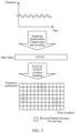
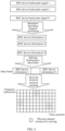
- the network-side device may receive second indication information from the terminal, where the second indication information is used to explicitly indicate a length of the data frame; and/or the network-side device may receive third indication information from the terminal, where the third indication information is used to implicitly indicate a length of the data frame.
- the third indication information includes separators inserted at the start and the end of the data frame.
- the terminal implicitly indicates the length of the data frame by using the separators inserted at the start and the end of the data frame.
- the separator is, for example, data with a fixed pattern, for example, 111 or 011.
- the network-side device may send fourth indication information to the terminal, where the fourth indication information is used to indicate the configuration of the first information, to be specific, explicitly indicate the configuration of the first information; and/or the network-side device may send control information to the BSC device, where the control information is used for the terminal to determine the configuration of the first information based on the control information after detecting the control information, to be specific, the network implicitly indicates the configuration of the first information by using the control information sent to the BSC device.
- the fourth indication information includes, but is not limited to, RRC signaling, a MAC CE, DCI, and the like.
- the information reporting method provided in the embodiments of this application may be performed by an information reporting apparatus.
- an information reporting apparatus provided in the embodiments of this application is described by using an example in which the information reporting apparatus performs the information reporting method.
- FIG. 8 is a schematic structural diagram of an information reporting apparatus according to an embodiment of this application.
- the apparatus is applied to a terminal.
- the information reporting apparatus 80 includes:
- the content of the backscatter signal includes at least one of the following: control information of the BSC device and data information of the BSC device.
- the content of the backscatter signal includes at least one of the following:
- the second content includes at least one of the following:
- the target event includes at least one of the following:
- the first information is associated with backscatter signal(s) of one or more BSC devices.
- the information reporting apparatus 80 further includes: a filling module, configured to pad pre-agreed-upon information to a first field of the first information, where the first field is used to carry information related to the backscatter signal of the first BSC device.
- the first information is carried in a PUSCH and/or a PUCCH.
- the information reporting apparatus 80 further includes: an execution module, configured to perform at least one of the following:
- the data frame has a fixed length, or the data frame has a variable length.
- the information reporting apparatus 80 in this embodiment of this application may be an electronic device, for example, an electronic device with an operating system; or may be a component in an electronic device, for example, an integrated circuit or a chip.
- the electronic device may be a terminal or another device other than the terminal.
- the terminal may include but is not limited to the aforementioned types of the terminal 11, and the another device may be a server, a network attached storage (Network Attached Storage, NAS), or the like. This is not specifically limited in the embodiments of this application.
- the third receiving module 91 is specifically configured to perform at least one of the following:
- the data frame has a fixed length, or the data frame has a variable length.
- the information receiving apparatus 90 further includes: a fourth receiving module, configured to perform at least one of the following:
- the second indication information includes information carried in a second field of the data frame; and the third indication information includes separators inserted at the start and the end of the data frame.
- the information receiving apparatus 90 further includes: a second sending module, configured to perform at least one of the following:
- the information receiving apparatus 90 provided in this embodiment of this application is capable of implementing the processes implemented in the method embodiment shown in FIG. 7 , with the same technical effect achieved. To avoid repetition, details are not described herein again.
- an embodiment of this application further provides a communication device 100, including a processor 101 and a memory 102.
- the memory 102 stores a program or instructions capable of being executed by the processor 101.
- the communication device 100 is a terminal
- the program or instructions are executed by the processor 101
- the steps in the embodiment of the information reporting method shown in FIG. 3 are implemented, with the same technical effect achieved.
- the communication device 100 is a network-side device
- the program or instructions are executed by the processor 101
- the steps in the embodiment of the information receiving method shown in FIG. 7 are implemented, with the same technical effect achieved. To avoid repetition, details are not described herein again.
- An embodiment of this application further provides a terminal, including a processor and a communication interface.
- the communication interface is configured to receive a backscatter signal from a backscatter communication BSC device.
- the processor is configured to determine first information based on the backscatter signal, where the first information includes at least one of the following: content of the backscatter signal, first indication information, and information of a first event, the first indication information is used to indicate whether a target event occurs when the terminal receives the backscatter signal within first time, and the first event is a target event that occurs when the terminal receives the backscatter signal within the first time.
- the communication interface is further configured to report the first information.
- the terminal embodiment corresponds to the foregoing terminal-side method embodiment, and all implementation processes and implementations of the foregoing method embodiment are applicable to the terminal embodiment, with the same technical effect achieved.
- FIG. 11 is a schematic diagram of a hardware structure of a terminal for implementing the embodiments of this application.
- the terminal 1100 includes but is not limited to at least some of components such as a radio frequency unit 1101, a network module 1102, an audio output unit 1103, an input unit 1104, a sensor 1105, a display unit 1106, a user input unit 1107, an interface unit 1108, a memory 1109, and a processor 1110.
- the terminal 1100 may further include a power supply (for example, a battery) that supplies power to each component.
- the power supply may be logically connected to the processor 1110 through a power management system, so that functions such as charging management, discharging management, and power consumption management are implemented through the power management system.
- the terminal structure shown in FIG. 11 does not constitute a limitation on the terminal.
- the terminal may include more or fewer components than those shown in the figure, or some components may be combined, or different component arrangements may be used. Details are not described herein again.
- the input unit 1104 may include a graphics processing unit (Graphics Processing Unit, GPU) 11041 and a microphone 11042.
- the graphics processing unit 11041 processes image data of a static picture or a video that is obtained by an image capture apparatus (for example, a camera) in a video capture mode or an image capture mode.
- the display unit 1106 may include a display panel 11061.
- the display panel 11061 may be configured in a form of a liquid crystal display, an organic light-emitting diode, or the like.
- the user input unit 1107 includes at least one of a touch panel 11071 and other input devices 11072.
- the touch panel 11071 is also referred to as a touchscreen.
- the touch panel 11071 may include two parts: a touch detection apparatus and a touch controller.
- the other input devices 11072 may include but are not limited to a physical keyboard, a function button (such as a volume control button or an on/off button), a trackball, a mouse, and a joystick. Details are not described herein.
- the radio frequency unit 1101 may transmit the downlink data to the processor 1110 for processing.
- the radio frequency unit 1101 may send uplink data to the network-side device.
- the radio frequency unit 1101 includes but is not limited to an antenna, an amplifier, a transceiver, a coupler, a low noise amplifier, a duplexer, and the like.
- the memory 1109 may be configured to store software programs or instructions and various data.
- the memory 1109 may mainly include a first storage region for storing a program or instructions and a second storage region for storing data.
- the first storage region may store an operating system, an application or instructions required by at least one function (for example, an audio play function or an image play function), and the like.
- the memory 1109 may include a volatile memory or a non-volatile memory, or the memory 1109 may include both a volatile memory and a non-volatile memory.
- the non-volatile memory may be a read-only memory (Read-Only Memory, ROM), a programmable read-only memory (Programmable ROM, PROM), an erasable programmable read-only memory (Erasable PROM, EPROM), an electrically erasable programmable read-only memory (Electrically EPROM, EEPROM), or a flash memory.
- ROM Read-Only Memory
- PROM programmable read-only memory
- Erasable PROM Erasable PROM
- EPROM electrically erasable programmable read-only memory
- EEPROM electrically erasable programmable read-only memory
- the volatile memory may be a random access memory (Random Access Memory, RAM), a static random access memory (Static RAM, SRAM), a dynamic random access memory (Dynamic RAM, DRAM), a synchronous dynamic random access memory (Synchronous DRAM, SDRAM), a double data rate synchronous dynamic random access memory (Double Data Rate SDRAM, DDRSDRAM), an enhanced synchronous dynamic random access memory (Enhanced SDRAM, ESDRAM), a synchlink dynamic random access memory (Synchlink DRAM, SLDRAM), or a direct rambus random access memory (Direct Rambus RAM, DRRAM).
- RAM Random Access Memory
- SRAM static random access memory
- DRAM dynamic random access memory
- DRAM synchronous dynamic random access memory
- SDRAM double data rate synchronous dynamic random access memory
- Enhanced SDRAM, ESDRAM enhanced synchronous dynamic random access memory
- Synchlink DRAM, SLDRAM synchlink dynamic random access memory
- Direct Rambus RAM Direct Rambus RAM
- the processor 1110 may include one or more processing units.
- the processor 1110 integrates an application processor and a modem processor.
- the application processor mainly processes operations related to an operating system, a user interface, an application, and the like.
- the modem processor mainly processes wireless communication signals, for example, is a baseband processor. It can be understood that the modem processor may alternatively not be integrated in the processor 1110.
- the radio frequency unit 1101 is configured to receive a backscatter signal from a backscatter communication BSC device.
- the processor 1110 is configured to determine first information based on the backscatter signal, where the first information includes at least one of the following: content of the backscatter signal, first indication information, and information of a first event, the first indication information is used to indicate whether a target event occurs when the terminal receives the backscatter signal within first time, and the first event is a target event that occurs when the terminal receives the backscatter signal within the first time.
- the radio frequency unit 1101 is further configured to report the first information.
Landscapes
- Engineering & Computer Science (AREA)
- Computer Networks & Wireless Communication (AREA)
- Signal Processing (AREA)
- Quality & Reliability (AREA)
- Physics & Mathematics (AREA)
- Electromagnetism (AREA)
- Mobile Radio Communication Systems (AREA)
Applications Claiming Priority (2)
| Application Number | Priority Date | Filing Date | Title |
|---|---|---|---|
| CN202210623466.1A CN117200874A (zh) | 2022-06-01 | 2022-06-01 | 信息上报方法、接收方法、装置、终端及网络侧设备 |
| PCT/CN2023/097759 WO2023232104A1 (zh) | 2022-06-01 | 2023-06-01 | 信息上报方法、接收方法、装置、终端及网络侧设备 |
Publications (2)
| Publication Number | Publication Date |
|---|---|
| EP4535685A1 true EP4535685A1 (de) | 2025-04-09 |
| EP4535685A4 EP4535685A4 (de) | 2025-09-10 |
Family
ID=89000381
Family Applications (1)
| Application Number | Title | Priority Date | Filing Date |
|---|---|---|---|
| EP23815281.3A Pending EP4535685A4 (de) | 2022-06-01 | 2023-06-01 | Informationsmeldeverfahren und -vorrichtung, informationsempfangsverfahren und -vorrichtung, endgerät und netzwerkseitige vorrichtung |
Country Status (4)
| Country | Link |
|---|---|
| US (1) | US20250097939A1 (de) |
| EP (1) | EP4535685A4 (de) |
| CN (1) | CN117200874A (de) |
| WO (1) | WO2023232104A1 (de) |
Families Citing this family (5)
| Publication number | Priority date | Publication date | Assignee | Title |
|---|---|---|---|---|
| US20240422767A1 (en) * | 2023-06-16 | 2024-12-19 | Qualcomm Incorporated | Indicating resource usage |
| WO2024222068A1 (en) * | 2024-01-17 | 2024-10-31 | Lenovo (Beijing) Limited | Power control in backscattered communication system |
| CN120676397A (zh) * | 2024-03-19 | 2025-09-19 | 华为技术有限公司 | 通信方法及装置 |
| WO2025208429A1 (zh) * | 2024-04-03 | 2025-10-09 | 富士通株式会社 | 设备识别方法以及装置 |
| CN119743845B (zh) * | 2024-12-24 | 2025-12-12 | 中国电信股份有限公司技术创新中心 | 无线通信帧选择方法、装置、计算机设备和存储介质 |
Family Cites Families (4)
| Publication number | Priority date | Publication date | Assignee | Title |
|---|---|---|---|---|
| NL2015432B1 (en) * | 2015-09-14 | 2017-03-29 | Univ Delft Tech | Method of transmitting data from a mobile transmitter device to a host unit, and mobile transmitter device. |
| US10469516B2 (en) * | 2016-04-28 | 2019-11-05 | Qualcomm Incorporated | Techniques for associating measurement data acquired at a wireless communication device with current values of time and location obtained by a user equipment and acknowledged by the wireless communication device |
| CN107786255A (zh) * | 2016-08-30 | 2018-03-09 | 华为技术有限公司 | 一种与射频设备通信的方法、装置及系统 |
| CN111712727B (zh) * | 2018-02-13 | 2023-01-06 | 华为技术有限公司 | 协作辅助位置估计技术 |
-
2022
- 2022-06-01 CN CN202210623466.1A patent/CN117200874A/zh active Pending
-
2023
- 2023-06-01 WO PCT/CN2023/097759 patent/WO2023232104A1/zh not_active Ceased
- 2023-06-01 EP EP23815281.3A patent/EP4535685A4/de active Pending
-
2024
- 2024-11-26 US US18/959,656 patent/US20250097939A1/en active Pending
Also Published As
| Publication number | Publication date |
|---|---|
| EP4535685A4 (de) | 2025-09-10 |
| WO2023232104A1 (zh) | 2023-12-07 |
| US20250097939A1 (en) | 2025-03-20 |
| CN117200874A (zh) | 2023-12-08 |
Similar Documents
| Publication | Publication Date | Title |
|---|---|---|
| EP4535685A1 (de) | Informationsmeldeverfahren und -vorrichtung, informationsempfangsverfahren und -vorrichtung, endgerät und netzwerkseitige vorrichtung | |
| EP4546884A1 (de) | Aufwecksignalüberwachungsverfahren und -vorrichtung, elektronische vorrichtung, netzwerkvorrichtung und medium | |
| US20250150178A1 (en) | Measurement processing method and apparatus, and device | |
| US20250016751A1 (en) | Transmission Method, Terminal, and Network-Side Device | |
| US12598051B2 (en) | Transmission direction determining method and apparatus, terminal, and network side device | |
| US20240154773A1 (en) | Tci state determining method and apparatus, terminal, and network-side device | |
| US20240357664A1 (en) | Communication operation execution method and apparatus, terminal, and storage medium | |
| US20240414655A1 (en) | Information responding method, information sending method, terminal, and network-side device | |
| US20250184895A1 (en) | Information transmission method and apparatus, receiving end, and sending end | |
| CN117200820A (zh) | 反向散射通信方法及设备 | |
| US20240023108A1 (en) | Method and apparatus for determining pucch resource, and terminal | |
| US20250324291A1 (en) | Data collection method and apparatus, terminal, and network-side device | |
| US20250261202A1 (en) | Method for common pucch transmission with repetitions, terminal, and network-side device | |
| US20250055652A1 (en) | Beam information determination method, and terminal, and network-side device | |
| WO2023116685A1 (zh) | Pei的配置方法、终端及网络侧设备 | |
| US20250024247A1 (en) | Information reporting method and apparatus, terminal, and network-side device | |
| US20240356611A1 (en) | Channel state information csi feedback method and apparatus, terminal, and network-side device | |
| US20240334495A1 (en) | Prach transmission method and apparatus, and terminal | |
| WO2023186083A1 (zh) | 发起bsc链路建立的方法、装置、设备和存储介质 | |
| EP4583554A1 (de) | Verfahren und vorrichtung zur kapazitätsanzeige sowie endgerät und medium | |
| US20250176001A1 (en) | Resource Configuration Method, Terminal, and Service Base Station | |
| EP4715682A1 (de) | Modellverarbeitungsverfahren und -vorrichtung sowie endgerät und netzwerkseitige vorrichtung | |
| US20240397384A1 (en) | Information transmission method and apparatus, terminal, and storage medium | |
| EP4412133A1 (de) | Gemeinsames planungsverfahren und vorrichtung | |
| US20240340969A1 (en) | Prach transmission method and apparatus, and terminal |
Legal Events
| Date | Code | Title | Description |
|---|---|---|---|
| STAA | Information on the status of an ep patent application or granted ep patent |
Free format text: STATUS: THE INTERNATIONAL PUBLICATION HAS BEEN MADE |
|
| PUAI | Public reference made under article 153(3) epc to a published international application that has entered the european phase |
Free format text: ORIGINAL CODE: 0009012 |
|
| STAA | Information on the status of an ep patent application or granted ep patent |
Free format text: STATUS: REQUEST FOR EXAMINATION WAS MADE |
|
| 17P | Request for examination filed |
Effective date: 20241230 |
|
| AK | Designated contracting states |
Kind code of ref document: A1 Designated state(s): AL AT BE BG CH CY CZ DE DK EE ES FI FR GB GR HR HU IE IS IT LI LT LU LV MC ME MK MT NL NO PL PT RO RS SE SI SK SM TR |
|
| A4 | Supplementary search report drawn up and despatched |
Effective date: 20250811 |
|
| DAV | Request for validation of the european patent (deleted) | ||
| DAX | Request for extension of the european patent (deleted) | ||
| RIC1 | Information provided on ipc code assigned before grant |
Ipc: H04B 7/22 20060101AFI20250805BHEP Ipc: H04B 17/309 20150101ALI20250805BHEP Ipc: H04W 72/1268 20230101ALI20250805BHEP |