EP4535738A1 - Procédé et appareil de gestion de faisceau, équipement utilisateur et dispositif de réseau - Google Patents
Procédé et appareil de gestion de faisceau, équipement utilisateur et dispositif de réseau Download PDFInfo
- Publication number
- EP4535738A1 EP4535738A1 EP22944158.9A EP22944158A EP4535738A1 EP 4535738 A1 EP4535738 A1 EP 4535738A1 EP 22944158 A EP22944158 A EP 22944158A EP 4535738 A1 EP4535738 A1 EP 4535738A1
- Authority
- EP
- European Patent Office
- Prior art keywords
- sub
- model
- beam index
- beams
- receiving
- Prior art date
- Legal status (The legal status is an assumption and is not a legal conclusion. Google has not performed a legal analysis and makes no representation as to the accuracy of the status listed.)
- Pending
Links
Images




Classifications
-
- H—ELECTRICITY
- H04—ELECTRIC COMMUNICATION TECHNIQUE
- H04W—WIRELESS COMMUNICATION NETWORKS
- H04W24/00—Supervisory, monitoring or testing arrangements
- H04W24/08—Testing, supervising or monitoring using real traffic
-
- G—PHYSICS
- G06—COMPUTING OR CALCULATING; COUNTING
- G06F—ELECTRIC DIGITAL DATA PROCESSING
- G06F30/00—Computer-aided design [CAD]
- G06F30/20—Design optimisation, verification or simulation
- G06F30/27—Design optimisation, verification or simulation using machine learning, e.g. artificial intelligence, neural networks, support vector machines [SVM] or training a model
-
- G—PHYSICS
- G06—COMPUTING OR CALCULATING; COUNTING
- G06N—COMPUTING ARRANGEMENTS BASED ON SPECIFIC COMPUTATIONAL MODELS
- G06N3/00—Computing arrangements based on biological models
- G06N3/02—Neural networks
- G06N3/04—Architecture, e.g. interconnection topology
- G06N3/044—Recurrent networks, e.g. Hopfield networks
- G06N3/0442—Recurrent networks, e.g. Hopfield networks characterised by memory or gating, e.g. long short-term memory [LSTM] or gated recurrent units [GRU]
-
- G—PHYSICS
- G06—COMPUTING OR CALCULATING; COUNTING
- G06N—COMPUTING ARRANGEMENTS BASED ON SPECIFIC COMPUTATIONAL MODELS
- G06N3/00—Computing arrangements based on biological models
- G06N3/02—Neural networks
- G06N3/04—Architecture, e.g. interconnection topology
- G06N3/045—Combinations of networks
-
- G—PHYSICS
- G06—COMPUTING OR CALCULATING; COUNTING
- G06N—COMPUTING ARRANGEMENTS BASED ON SPECIFIC COMPUTATIONAL MODELS
- G06N3/00—Computing arrangements based on biological models
- G06N3/02—Neural networks
- G06N3/04—Architecture, e.g. interconnection topology
- G06N3/0464—Convolutional networks [CNN, ConvNet]
-
- G—PHYSICS
- G06—COMPUTING OR CALCULATING; COUNTING
- G06N—COMPUTING ARRANGEMENTS BASED ON SPECIFIC COMPUTATIONAL MODELS
- G06N3/00—Computing arrangements based on biological models
- G06N3/02—Neural networks
- G06N3/08—Learning methods
- G06N3/09—Supervised learning
-
- H—ELECTRICITY
- H04—ELECTRIC COMMUNICATION TECHNIQUE
- H04B—TRANSMISSION
- H04B7/00—Radio transmission systems, i.e. using radiation field
- H04B7/02—Diversity systems; Multi-antenna system, i.e. transmission or reception using multiple antennas
- H04B7/04—Diversity systems; Multi-antenna system, i.e. transmission or reception using multiple antennas using two or more spaced independent antennas
- H04B7/06—Diversity systems; Multi-antenna system, i.e. transmission or reception using multiple antennas using two or more spaced independent antennas at the transmitting station
- H04B7/0613—Diversity systems; Multi-antenna system, i.e. transmission or reception using multiple antennas using two or more spaced independent antennas at the transmitting station using simultaneous transmission
- H04B7/0615—Diversity systems; Multi-antenna system, i.e. transmission or reception using multiple antennas using two or more spaced independent antennas at the transmitting station using simultaneous transmission of weighted versions of same signal
- H04B7/0619—Diversity systems; Multi-antenna system, i.e. transmission or reception using multiple antennas using two or more spaced independent antennas at the transmitting station using simultaneous transmission of weighted versions of same signal using feedback from receiving side
- H04B7/0621—Feedback content
- H04B7/063—Parameters other than those covered in groups H04B7/0623 - H04B7/0634, e.g. channel matrix rank or transmit mode selection
-
- H—ELECTRICITY
- H04—ELECTRIC COMMUNICATION TECHNIQUE
- H04B—TRANSMISSION
- H04B7/00—Radio transmission systems, i.e. using radiation field
- H04B7/02—Diversity systems; Multi-antenna system, i.e. transmission or reception using multiple antennas
- H04B7/04—Diversity systems; Multi-antenna system, i.e. transmission or reception using multiple antennas using two or more spaced independent antennas
- H04B7/06—Diversity systems; Multi-antenna system, i.e. transmission or reception using multiple antennas using two or more spaced independent antennas at the transmitting station
- H04B7/0686—Hybrid systems, i.e. switching and simultaneous transmission
- H04B7/0695—Hybrid systems, i.e. switching and simultaneous transmission using beam selection
-
- H—ELECTRICITY
- H04—ELECTRIC COMMUNICATION TECHNIQUE
- H04B—TRANSMISSION
- H04B7/00—Radio transmission systems, i.e. using radiation field
- H04B7/02—Diversity systems; Multi-antenna system, i.e. transmission or reception using multiple antennas
- H04B7/04—Diversity systems; Multi-antenna system, i.e. transmission or reception using multiple antennas using two or more spaced independent antennas
- H04B7/06—Diversity systems; Multi-antenna system, i.e. transmission or reception using multiple antennas using two or more spaced independent antennas at the transmitting station
- H04B7/0686—Hybrid systems, i.e. switching and simultaneous transmission
- H04B7/0695—Hybrid systems, i.e. switching and simultaneous transmission using beam selection
- H04B7/06952—Selecting one or more beams from a plurality of beams, e.g. beam training, management or sweeping
-
- H—ELECTRICITY
- H04—ELECTRIC COMMUNICATION TECHNIQUE
- H04B—TRANSMISSION
- H04B7/00—Radio transmission systems, i.e. using radiation field
- H04B7/02—Diversity systems; Multi-antenna system, i.e. transmission or reception using multiple antennas
- H04B7/04—Diversity systems; Multi-antenna system, i.e. transmission or reception using multiple antennas using two or more spaced independent antennas
- H04B7/06—Diversity systems; Multi-antenna system, i.e. transmission or reception using multiple antennas using two or more spaced independent antennas at the transmitting station
- H04B7/0686—Hybrid systems, i.e. switching and simultaneous transmission
- H04B7/0695—Hybrid systems, i.e. switching and simultaneous transmission using beam selection
- H04B7/06952—Selecting one or more beams from a plurality of beams, e.g. beam training, management or sweeping
- H04B7/0696—Determining beam pairs
- H04B7/06962—Simultaneous selection of transmit [Tx] and receive [Rx] beams at both sides of a link
-
- H—ELECTRICITY
- H04—ELECTRIC COMMUNICATION TECHNIQUE
- H04B—TRANSMISSION
- H04B7/00—Radio transmission systems, i.e. using radiation field
- H04B7/02—Diversity systems; Multi-antenna system, i.e. transmission or reception using multiple antennas
- H04B7/04—Diversity systems; Multi-antenna system, i.e. transmission or reception using multiple antennas using two or more spaced independent antennas
- H04B7/08—Diversity systems; Multi-antenna system, i.e. transmission or reception using multiple antennas using two or more spaced independent antennas at the receiving station
- H04B7/0868—Hybrid systems, i.e. switching and combining
- H04B7/088—Hybrid systems, i.e. switching and combining using beam selection
-
- H—ELECTRICITY
- H04—ELECTRIC COMMUNICATION TECHNIQUE
- H04L—TRANSMISSION OF DIGITAL INFORMATION, e.g. TELEGRAPHIC COMMUNICATION
- H04L27/00—Modulated-carrier systems
-
- H—ELECTRICITY
- H04—ELECTRIC COMMUNICATION TECHNIQUE
- H04W—WIRELESS COMMUNICATION NETWORKS
- H04W72/00—Local resource management
- H04W72/04—Wireless resource allocation
- H04W72/044—Wireless resource allocation based on the type of the allocated resource
- H04W72/046—Wireless resource allocation based on the type of the allocated resource the resource being in the space domain, e.g. beams
-
- H—ELECTRICITY
- H04—ELECTRIC COMMUNICATION TECHNIQUE
- H04W—WIRELESS COMMUNICATION NETWORKS
- H04W72/00—Local resource management
- H04W72/20—Control channels or signalling for resource management
- H04W72/21—Control channels or signalling for resource management in the uplink direction of a wireless link, i.e. towards the network
Definitions
- Embodiments of the present application relate to the field of mobile communication technology, and in particular to a beam management method and apparatus, a user equipment, and a network device.
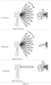
- the analog beamforming technology can reduce the implementation complexity of a device while enhancing the network coverage.
- the analog beamforming not only may be used for a network device, but also may be used for a user equipment (UE).
- UE user equipment
- Embodiments of the present application provide a beam management method and apparatus, a user equipment, a network device, a chip, a computer-readable storage medium, a computer program product, and a computer program.
- the chip includes: a processor, used to invoke and execute a computer program from a memory, causing a device equipped with the chip to perform the beam management method described above.
- the computer-readable storage medium provided in the embodiments of the present application is used to store a computer program, where the computer program causes a computer to perform the beam management method described above.
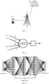
- the network device 120 may be an access network device that communicates with the user equipment 110.
- the access network device may provide a communication coverage for a specific geographical area and may communicate with the user equipment 110 located within the coverage area.
- the access network device may be a base station (gNB) in an NR system.
- gNB base station
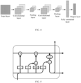
- FIG. 4 is a typical convolutional neural network.
- basic structures of the convolutional neural network includes: an input layer, multiple convolutional layers, multiple pooling layers, a fully connected layer and an output layer.
- An input of the input layer is an input of the convolutional neural network
- an output of the output layer is an output of the convolutional neural network.
- each neuron of a convolution kernel in a convolution layer is locally connected to an input of the neuron, and a maximum value or a feature of an average value of a part of a certain layer is extracted by introducing an pooling layer, thus effectively reducing parameters of the network and mines local features, so that the convolutional neural network may converge quickly and excellent performance is obtained.
- the beam described in the embodiments of the present application refers to a transmitting beam or a receiving beam
- the beam pair refers to a pair of transmitting beam and receiving beam.
- multiple beams measured by the UE are a subset of all beams.
- the all beams refer to all transmitting beams or all receiving beams, that is, all transmitting beams of a network device or all receiving beams of a UE.
- measurement for a beam or a beam pair refers to measurement for a reference signal associated with the beam or the beam pair.
- the link quality includes at least one of: a layer 1-reference signal receiving power (L1-RSRP), a layer 1-signal to interference plus noise ratio (L1-SINR), or a layer 1-reference signal receiving quality (L1-RSRQ).
- L1-RSRP layer 1-reference signal receiving power
- L1-SINR layer 1-signal to interference plus noise ratio
- L1-RSRQ layer 1-reference signal receiving quality
- the UE determines the uplink feedback information by utilizing the first sub-model based on the link qualities of the multiple beams.
- the at least one receiving beam index is indexes of K receiving beams with a best link quality in the multiple beams or the multiple beam pairs, where K is a positive integer.
- the at least one receiving beam index may be denoted as K optimal receiving beam indexes.
- a value of K may be configured by the network, or may be predefined, or may be determined based on the implementation of the UE itself.
- the link quality is a link quality of a beam or a link quality of a beam pair
- there is a correspondence relationship between a transmitting beam and the link quality or there is a correspondence relationship between a receiving beam and the link quality, or there is a correspondence relationship between a pair of a transmitting beam and a receiving beam and the link quality.
- the K optimal receiving beam indexes output from the first sub-model on the UE side are sorted according to a sort of corresponding link qualities (e.g., in an order from high qualities to low qualities); the K optimal transmitting beam indexes output from the second sub-model on the network device side are sorted according to a sort of corresponding link qualities (e.g., in an order from high qualities to low qualities).
- the first sub-model includes an output layer.
- the UE performs processing on the link qualities of the multiple beams or the multiple beam pairs by utilizing the first sub-model, outputs the at least one receiving beam index through a first part of nodes of the output layer, and outputs the first information through a second part of the nodes of the output layer.
- the first information is used to determine the uplink feedback information.
- the first sub-model further includes a quantization layer, and the UE performs quantization processing on the first information through the quantization layer to obtain the uplink feedback information.
- the first sub-model includes a first output layer and a second output layer.
- the UE performing process on the link qualities of the multiple beams or the multiple beam pairs by utilizing the first sub-model, outputs the at least one receiving beam index through the first output layer, and outputs first information through the second output layer.
- the first information is used to determine uplink feedback information.
- the first sub-model further includes a quantization layer, and the UE performs quantization processing on the first information through the quantization layer to obtain the uplink feedback information.
- the first output layer in a case where the first output layer is located behind the second output layer, the first output layer is a last neural network layer of the first sub-model, and the second output layer is a first neural network layer of the first sub-model.
- this kind of association may be a direct association (corresponding to a case where the two layers are adjacent) or an indirect association (corresponding to a case where the two layers are not adjacent).
- the uplink feedback information is a first bit sequence, and the first bit sequence is used to determine the at least one transmitting beam index and at least one link quality corresponding to the at least one transmitting beam index.
- the uplink feedback information is a second bit sequence
- the second bit sequence is used to indicate the link qualities of the multiple beams or the multiple beam pairs.
- the link qualities of the multiple beams or the multiple beam pairs are used to determine the at least one transmitting beam index and the at least one link quality corresponding to the at least one transmitting beam index.
- the UE determines a first receiving beam index from the multiple receiving beam indexes to receive the downlink transmission by adopting a receiving beam indicated by the first receiving beam index.
- the first sub-model in the solutions described above is pre-trained, and the network device may train the first sub-model and issue a trained first sub-model to the UE.
- the second sub-model in the solutions described above is also pre-trained, and the second sub-model may be trained by the network device.
- the first sub-model and the second sub-model are trained jointly; or the first sub-model and the second sub-model are trained independently.
- the first sub-model and the second sub-model share a same loss function.
- the loss function may be understood as a joint loss function of the first sub-model and the second sub-model, and weights of the two sub-models are co-optimized through the joint loss function. Specifically, a loss value between output data and a label of a whole model is calculated through the joint loss function to determine whether the loss value meets a preset condition.
- the first sub-model and the second sub-model have independent loss functions, and the weights of the two sub-models are optimized respectively through the two loss functions. Specifically, a loss value between output data of the first sub-model and a label of the output data of the first sub-model is calculated through a first loss function, and whether the loss value meets a preset condition is determined. If the loss value does not meet the preset condition, the first sub-model is updated according to the loss value (including but not limited to updating the weight of the first sub-model), and the steps described above are continuously iterated until the loss value meets the preset condition and the training of the first sub-model is completed.
- the second sub-model and the first sub-model need to be paired for training, that is, the first sub-model and the second sub-model need to be trained jointly.
- the first sub-model and the second sub-model also need to be deployed in pairs.
- beam pair refers to a pair of a transmitting beam and a receiving beam.
- the UE selects the one optimal receiving beam output by the UE-side sub-model for receiving downlink transmission
- the NW selects the one optimal transmitting beam output by the NW-side sub-model for sending the downlink transmission.
- matching of an optimal beam pair is achieved automatically through an optimal receiving beam indicated by the one optimal receiving beam index output by the UE-side sub-model and an optimal transmitting beam indicated by the one optimal transmitting beam index output by the NW-side sub-model without indicating for which beams can be used by the UE side and the NW side.
- a link quality of the optimal beam pair is given through the L1-RSRP output by the NW-side sub-model.
- the uplink feedback information output layer outputs first information, where the first information is output as uplink feedback information after passing through a quantization layer.
- the uplink feedback information serves as an input of the NW-side sub-model.
- the uplink feedback information is a section of bit sequence.
- the bit sequence does not explicitly indicate K optimal transmitting beam indexes and L1-RSRPs corresponding to the K optimal transmitting beam indexes, but implicitly includes information of the K optimal transmitting beam indexes and L1-RSRPs corresponding to the K optimal transmitting beam indexes.
- the information may be extracted by a matched NW-side sub-model.
- the UE-side sub-model and the NW-side sub-model need to be paired for training and deployment, so that the NW can correctly predict the K optimal transmitting beam indexes and the L1-RSRPs corresponding to the K optimal transmitting beam indexes from the uplink feedback information.
- the uplink feedback information output layer in FIG. 9-2 is a portion of the one neural network layer of the hidden layer, which is however not limited thereto, and the uplink feedback information output layer may also be the whole of the one neural network layer of the hidden layer.
- the optimal receiving beam index output layer outputs K optimal receiving beam indexes
- the uplink feedback information output layer outputs first information.
- the first information is output as uplink feedback information after passing through a quantization layer.
- the uplink feedback information serves as an input of the NW-side sub-model.
- the uplink feedback information is a section of bit sequence.
- the bit sequence does not explicitly indicate K optimal transmitting beam indexes and L1-RSRPs corresponding to the K optimal transmitting beam indexes, but implicitly includes information of the K optimal transmitting beam indexes and the L1-RSRPs corresponding to the K optimal transmitting beam indexes.
- the information may be extracted by a matched NW-side sub-model.
- the UE-side sub-model includes an input layer, a hidden layer, and an output layer.
- An input of the input layer is a matrix in which L1-RSRPs of measured M beam pairs are arranged in a specified order.
- the hidden layer is composed of multiple fully connected layers.
- An output layer outputs K optimal receiving beam indexes.
- the L1-RSRPs of the M beam pairs of the input layer are used as first information and are output as uplink feedback information after passing through a quantization layer. After the uplink feedback information is reported to the NW side, the uplink feedback information serves as an input of the NW-side sub-model.
- the input of the UE-side sub-model includes values of L1-RSRPs of direct measurement beam pairs, and there is no quantization error; while the input of the NW-side sub-model is acquired from the uplink feedback information, so there is a quantization error.
- a data set required by the model includes the following parts:
- an offline training task is completed on the NW side.
- the NW side saves complete structures of the UE-side sub-model and the NW-side sub-model, and issues a trained UE-side sub-model (specifically including structures and parameters of the UE-side sub-model) to the UE through a downlink channel after the training is completed.
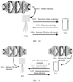
- the training process is shown in FIG. 10 , and includes the following steps.
- step 1001 the NW performs downlink beam scanning.
- step 1002 a UE reports a data set.
- the data set includes the following two parts: a first part as an input, i.e., an input of the UE-side sub-model, specifically L1-RSRPs of a portion of beam pairs of all measured beam pairs; and a second part as a label, i.e., labels of the UE-side sub-model and the NW-side sub-model, specifically K optimal transmitting beam indexes, K optimal receiving beam indexes and corresponding K L1-RSRPs.
- a first part as an input, i.e., an input of the UE-side sub-model, specifically L1-RSRPs of a portion of beam pairs of all measured beam pairs
- a second part as a label, i.e., labels of the UE-side sub-model and the NW-side sub-model, specifically K optimal transmitting beam indexes, K optimal receiving beam indexes and corresponding K L1-RSRPs.
- the UE-side sub-model outputs K (K>1) optimal receiving beam indexes, and the NW-side sub-model outputs K optimal transmitting beam indexes and L1-RSRPs corresponding to the K optimal transmitting beam indexes.
- step 1101 an NW performs downlink beam scanning.
- step 1102 the UE-side sub-model performs inference.
- the UE determines a corresponding optimal receiving beam index according to the optimal transmitting beam index indicated by the NW, and receives the downlink transmission by utilizing the receiving beam indicated by the optimal receiving beam index.
- downlink uplink
- sidelink sidelink
- downlink uplink
- uplink is used to represent that the transmission direction of signals or data is a second direction from a user equipment of a cell to a site
- sidelink is used to represent that the transmission direction of signals or data is a third direction from user equipment 1 to user equipment 2.
- a “downlink signal” represent that the transmission direction of the signal is the first direction.
- the term "and/or” is merely used to describe the association relationship between associated objects, representing that three types of relationships may exist.
- a and/or B may mean three cases where: A exists alone, both A and B exist, and B exists alone.
- a character "/” herein generally means that associated objects before and after " / " are in an "or” relationship.
- the multiple beams are multiple receiving beams or multiple transmitting beams
- the multiple beam pairs are multiple pairs of transmitting beam and receiving beam.
- the at least one receiving beam index includes indexes of K receiving beams with a best link quality in the multiple beams or the multiple beam pairs, where K is a positive integer.
- the at least one transmitting beam index includes indexes of K transmitting beams with a best link quality in the multiple beams or the multiple beam pairs, where K is a positive integer.
- the first sub-model includes an output layer; and the processing unit 1202 is configured to perform processing on the link qualities of the multiple beams or the multiple beam pairs by utilizing the first sub-model to output at least one receiving beam index through a first part of nodes of the output layer, and output first information through a second part of the nodes of the output layer, where the first information is used to determine the uplink feedback information.
- the second output layer is a last neural network layer of the first sub-model; and the first output layer is a middle neural network layer of the first sub-model.
- the first output layer in a case where the first output layer is located behind the second output layer, the first output layer is a last neural network layer of the first sub-model; and the second output layer is a first neural network layer of the first sub-model.
- an input of the first neural network layer includes the link qualities of the multiple beams or the multiple beam pairs.
- the sending unit 1203 is configured to report a data set to the network device, where the data set is used for the network device to train the first sub-model; and the receiving unit 1204 is configured to receive a trained first sub-model sent from the network device.
- the apparatus further includes: a sending unit 1303, configured to select a first transmission beam index from multiple transmission beam indexes in a case where the at least one transmission beam index includes the multiple transmission beam indexes to send downlink transmission by adopting a transmission beam indicated by the first transmission beam index.
- a sending unit 1303 configured to select a first transmission beam index from multiple transmission beam indexes in a case where the at least one transmission beam index includes the multiple transmission beam indexes to send downlink transmission by adopting a transmission beam indicated by the first transmission beam index.
- the at least one receiving beam index includes indexes of K receiving beams with a best link quality in the multiple beams or the multiple beam pairs, where K is a positive integer.
- the first sub-model and the second sub-model are trained jointly; or, the first sub-model and the second sub-model are trained independently.
- the communication device 1400 may further include a memory 1420.
- the processor 1410 may invoke and execute a computer program from the memory 1420 to implement the methods in the embodiments of the present application.
- the communication device 1400 may further include a transceiver 1430, and the processor 1410 may control the transceiver 1430 to communicate with other devices, specifically, to send information or data to other devices, or to receive information or data sent from other devices.
- the processor 1410 may control the transceiver 1430 to communicate with other devices, specifically, to send information or data to other devices, or to receive information or data sent from other devices.
- the transceiver 1430 may include a transmitter and a receiver.
- the transceiver 1430 may further include an antenna, and a number of antennas may be one or more.
- the communication device 1400 may specifically be a user equipment in the embodiments of the present application, and the communication device 1400 may implement the corresponding procedures implemented by the user equipment in respective methods in the embodiments of the present application, which will not be repeated herein for the sake of brevity.
- FIG. 15 is a schematic structural diagram of a chip in the embodiments of the present application.
- the chip 1500 shown in FIG. 15 includes a processor 1510, and the processor 1510 may invoke and execute a computer program from a memory to implement the methods in the embodiments of the present application.
- the chip mentioned in the embodiments of the present application may also be called a system-level chip, a system chip, a chip system or a system-on-chip chip, etc.
- the user equipment 1610 may be used to implement corresponding functions implemented by the user equipment in the methods described above, and the network device 1620 may be used to implement corresponding functions implemented by the network device in the methods described above, which will not be repeated herein for the sake of brevity.
- the processor in the embodiments of the present application may be an integrated circuit chip with signal processing capabilities.
- respective steps of the above method embodiments can be completed by an integrated logic circuit of hardware in a processor or an instruction in software form.
- the above-mentioned processor may be a general-purpose processor, a Digital Signal Processor (DSP), an Application Specific Integrated Circuit (ASIC), a Field Programmable Gate Array (FPGA) or other programmable logic devices, a discrete gate or a transistor logic device, or a discrete hardware component.
- DSP Digital Signal Processor
- ASIC Application Specific Integrated Circuit
- FPGA Field Programmable Gate Array
- a general-purpose processor may be a microprocessor, or the processor may also be any conventional processor, etc.
- the above memory is exemplary but not the limited illustration, e.g., the memory in embodiments of the present application may also be a static Random Access Memory (static RAM, SRAM), a dynamic Random Access Memory (dynamic RAM, DRAM), a synchronous dynamic Random Access Memory (synchronous DRAM, SDRAM), a double data rate synchronous dynamic Random Access Memory (double data rate SDRAM, DDR SDRAM), an enhanced synchronous dynamic Random Access Memory (enhanced SDRAM, ESDRAM), a synch link dynamic Random Access Memory (synch link DRAM, SLDRAM), and a Direct Rambus Random Access Memory (Direct Rambus RAM, DR RAM), etc. That is, the memory in the embodiments of the present application is intended to include, but not limited to, these and any other suitable types of memories.
- the computer-readable storage medium may be applied to the network device in the embodiments of the present application, and the computer program causes a computer to execute the corresponding processes implemented by the network device in respective methods in the embodiments of the present application, which will not be repeated herein for the sake of brevity.
- the computer-readable storage medium may be applied to the user equipment in the embodiments of the present application, and the computer program causes a computer to execute the corresponding processes implemented by the user equipment in respective methods in the embodiments of the present application, which will not be repeated herein for the sake of brevity.
- the embodiments of the present application further provide a computer program product, which includes a computer program instruction.
- the computer program product may be applied to the network device in the embodiments of the present application, and the computer program instruction causes a computer to execute the corresponding processes implemented by the network device in respective methods in the embodiments of the present application, which will not be repeated herein for the sake of brevity.
- the computer program may be applied to the user equipment in the embodiments of the present application.
- the computer program is executed on a computer, the computer is caused to execute the corresponding processes implemented by the user equipment in respective methods in the embodiments of the present application, which will not be repeated herein for the sake of brevity.
- the disclosed systems, apparatus, and method may be implemented in other ways.
- the apparatus embodiments described above are only schematic, for example, the division of the units is only the division of logical functions, and there may be other division methods in an actual implementation, for example, a plurality of units or components may be combined or integrated into another system, or some features may be ignored or not be performed.
- the coupling or direct coupling or communicative connection with each other as shown or discussed may be indirect coupling or communicative connection of apparatus or units via some interfaces, which may be electrical, mechanical, or in other forms.
- the units illustrated as separate components may be or may not be physically separated, and the components shown as units may be or may not be physical units, that is, they may be located in one place, or may also be distributed among a plurality of network units. A part or all of the units may be selected according to actual needs, to implement the purpose of the solutions of the embodiments.
- various functional units in the various embodiments of the present application may be integrated into one processing unit, or the various units may physically exist separately, or two or more units may be integrated into one unit.
Landscapes
- Engineering & Computer Science (AREA)
- Signal Processing (AREA)
- Computer Networks & Wireless Communication (AREA)
- Physics & Mathematics (AREA)
- Theoretical Computer Science (AREA)
- Evolutionary Computation (AREA)
- General Engineering & Computer Science (AREA)
- Artificial Intelligence (AREA)
- Software Systems (AREA)
- Mathematical Physics (AREA)
- General Physics & Mathematics (AREA)
- Biophysics (AREA)
- Life Sciences & Earth Sciences (AREA)
- Molecular Biology (AREA)
- General Health & Medical Sciences (AREA)
- Data Mining & Analysis (AREA)
- Computational Linguistics (AREA)
- Biomedical Technology (AREA)
- Computing Systems (AREA)
- Health & Medical Sciences (AREA)
- Computer Vision & Pattern Recognition (AREA)
- Medical Informatics (AREA)
- Computer Hardware Design (AREA)
- Geometry (AREA)
- Mobile Radio Communication Systems (AREA)
Applications Claiming Priority (1)
| Application Number | Priority Date | Filing Date | Title |
|---|---|---|---|
| PCT/CN2022/096170 WO2023230818A1 (fr) | 2022-05-31 | 2022-05-31 | Procédé et appareil de gestion de faisceau, équipement utilisateur et dispositif de réseau |
Publications (2)
| Publication Number | Publication Date |
|---|---|
| EP4535738A1 true EP4535738A1 (fr) | 2025-04-09 |
| EP4535738A4 EP4535738A4 (fr) | 2026-03-18 |
Family
ID=89026602
Family Applications (1)
| Application Number | Title | Priority Date | Filing Date |
|---|---|---|---|
| EP22944158.9A Pending EP4535738A4 (fr) | 2022-05-31 | 2022-05-31 | Procédé et appareil de gestion de faisceau, équipement utilisateur et dispositif de réseau |
Country Status (4)
| Country | Link |
|---|---|
| US (1) | US20250088880A1 (fr) |
| EP (1) | EP4535738A4 (fr) |
| CN (1) | CN119256526A (fr) |
| WO (1) | WO2023230818A1 (fr) |
Families Citing this family (3)
| Publication number | Priority date | Publication date | Assignee | Title |
|---|---|---|---|---|
| US20240048219A1 (en) * | 2022-08-05 | 2024-02-08 | Nokia Technologies Oy | Method, apparatus and computer program |
| US20250055549A1 (en) * | 2023-08-07 | 2025-02-13 | Samsung Electronics Co., Ltd. | System and method for beam tracking using graph neural networks |
| WO2025231623A1 (fr) * | 2024-05-07 | 2025-11-13 | 北京小米移动软件有限公司 | Procédés de gestion de faisceaux, dispositif de communication et support de stockage |
Family Cites Families (7)
| Publication number | Priority date | Publication date | Assignee | Title |
|---|---|---|---|---|
| KR102299326B1 (ko) * | 2013-09-27 | 2021-09-08 | 삼성전자주식회사 | 무선 통신 시스템에서 빔 정보 송수신 장치 및 방법 |
| US11330457B2 (en) * | 2017-07-25 | 2022-05-10 | Mediatek Inc. | Method for beam management with beam indication in wireless communication systems with beamforming |
| US10638482B2 (en) * | 2017-12-15 | 2020-04-28 | Qualcomm Incorporated | Methods and apparatuses for dynamic beam pair determination |
| US10608723B2 (en) * | 2018-02-15 | 2020-03-31 | Qualcomm Incorporated | Techniques for assisted beam refinement |
| CN112886996B (zh) * | 2019-11-29 | 2024-08-20 | 北京三星通信技术研究有限公司 | 信号接收方法、用户设备、电子设备及计算机存储介质 |
| CN114390580B (zh) * | 2020-10-20 | 2024-10-15 | 维沃移动通信有限公司 | 波束上报方法、波束信息确定方法及相关设备 |
| WO2022104700A1 (fr) * | 2020-11-20 | 2022-05-27 | Huawei Technologies Co., Ltd. | Ensemble de faisceaux pour un retour d'informations d'état de canal dans des systèmes mimo |
-
2022
- 2022-05-31 EP EP22944158.9A patent/EP4535738A4/fr active Pending
- 2022-05-31 WO PCT/CN2022/096170 patent/WO2023230818A1/fr not_active Ceased
- 2022-05-31 CN CN202280096417.5A patent/CN119256526A/zh active Pending
-
2024
- 2024-11-25 US US18/958,110 patent/US20250088880A1/en active Pending
Also Published As
| Publication number | Publication date |
|---|---|
| EP4535738A4 (fr) | 2026-03-18 |
| WO2023230818A1 (fr) | 2023-12-07 |
| CN119256526A (zh) | 2025-01-03 |
| US20250088880A1 (en) | 2025-03-13 |
Similar Documents
| Publication | Publication Date | Title |
|---|---|---|
| US20250088880A1 (en) | Beam management method, user equipment, and network device | |
| US20230245000A1 (en) | Model evaluation method and apparatus | |
| US12035421B2 (en) | Procedure for optimization of self-organizing network | |
| US20250287244A1 (en) | Measurement feedback method and apparatus, and storage medium | |
| US12010571B2 (en) | Spectral efficiency prediction with artificial intelligence for enhancing carrier aggregation and proactive radio resource management | |
| EP4422317A1 (fr) | Procédé et appareil de communication | |
| WO2024094166A1 (fr) | Procédé de transmission de rapport et appareil de communication | |
| EP4373159A1 (fr) | Fonctionnalité de modèle ai/ml dans des scénarios de transfert intercellulaire | |
| US20250240663A1 (en) | Transmission method and apparatus, communication device, and readable storage medium | |
| US20250125895A1 (en) | Wireless communication method, terminal device, and network device | |
| CN120956308A (zh) | 通信方法、系统、装置、设备及可读存储介质 | |
| WO2024098264A1 (fr) | Procédé et appareil de gestion de faisceaux, dispositif, support d'enregistrement, et produit-programme | |
| EP4642079A1 (fr) | Procédé et appareil pour générer un paramètre de seuil dynamique d'un réseau local sans fil | |
| WO2025035251A1 (fr) | Procédé et appareil de reprise après défaillance d'un modèle, dispositif terminal et dispositif de réseau | |
| EP4730685A1 (fr) | Procédé et appareil de transmission d'informations, et support de stockage | |
| US20260089728A1 (en) | Spatial filter determination method and apparatus, device, chip, and storage medium | |
| US20260030557A1 (en) | Model performance monitoring method and device, and chip | |
| GB2638217A (en) | Enhancement of beam reporting for beam prediction on the network side | |
| WO2025172898A1 (fr) | Amélioration de la production de rapport de faisceau pour permettre une prédiction de faisceau côté réseau | |
| WO2025119159A1 (fr) | Procédé et appareil de communication | |
| CN120881513A (zh) | 无线电地图获取方法和装置 | |
| CN120456046A (zh) | 一种通信方法及相关设备 | |
| WO2024246654A1 (fr) | Procédé de sélection de parties de modèle adaptatif pour un apprentissage continu collaboratif à l'aide de groupes d'ue | |
| WO2025260372A1 (fr) | Procédé et appareil de gestion de faisceau, dispositif terminal, dispositif de réseau, puce, support et produit programme | |
| CN120786449A (zh) | 发送信息的方法和通信装置 |
Legal Events
| Date | Code | Title | Description |
|---|---|---|---|
| STAA | Information on the status of an ep patent application or granted ep patent |
Free format text: STATUS: THE INTERNATIONAL PUBLICATION HAS BEEN MADE |
|
| PUAI | Public reference made under article 153(3) epc to a published international application that has entered the european phase |
Free format text: ORIGINAL CODE: 0009012 |
|
| STAA | Information on the status of an ep patent application or granted ep patent |
Free format text: STATUS: REQUEST FOR EXAMINATION WAS MADE |
|
| 17P | Request for examination filed |
Effective date: 20241227 |
|
| AK | Designated contracting states |
Kind code of ref document: A1 Designated state(s): AL AT BE BG CH CY CZ DE DK EE ES FI FR GB GR HR HU IE IS IT LI LT LU LV MC MK MT NL NO PL PT RO RS SE SI SK SM TR |
|
| DAV | Request for validation of the european patent (deleted) | ||
| DAX | Request for extension of the european patent (deleted) | ||
| A4 | Supplementary search report drawn up and despatched |
Effective date: 20260213 |
|
| RIC1 | Information provided on ipc code assigned before grant |
Ipc: H04L 27/00 20060101AFI20260209BHEP Ipc: G06F 30/27 20200101ALI20260209BHEP Ipc: G06N 3/02 20060101ALI20260209BHEP Ipc: G06N 20/00 20190101ALI20260209BHEP Ipc: H04B 7/06 20060101ALI20260209BHEP Ipc: H04W 24/08 20090101ALI20260209BHEP Ipc: H04W 72/044 20230101ALI20260209BHEP Ipc: H04W 72/21 20230101ALI20260209BHEP Ipc: H04B 7/08 20060101ALI20260209BHEP Ipc: G06N 3/0442 20230101ALI20260209BHEP Ipc: G06N 3/045 20230101ALI20260209BHEP Ipc: G06N 3/0464 20230101ALI20260209BHEP Ipc: G06N 3/09 20230101ALI20260209BHEP |