EP4535791A2 - Bildcodierungsverfahren auf transformationsbasis und vorrichtung dafür - Google Patents
Bildcodierungsverfahren auf transformationsbasis und vorrichtung dafür Download PDFInfo
- Publication number
- EP4535791A2 EP4535791A2 EP25158652.5A EP25158652A EP4535791A2 EP 4535791 A2 EP4535791 A2 EP 4535791A2 EP 25158652 A EP25158652 A EP 25158652A EP 4535791 A2 EP4535791 A2 EP 4535791A2
- Authority
- EP
- European Patent Office
- Prior art keywords
- transform
- flag
- lfnst
- block
- component
- Prior art date
- Legal status (The legal status is an assumption and is not a legal conclusion. Google has not performed a legal analysis and makes no representation as to the accuracy of the status listed.)
- Pending
Links
Images







Classifications
-
- H—ELECTRICITY
- H04—ELECTRIC COMMUNICATION TECHNIQUE
- H04N—PICTORIAL COMMUNICATION, e.g. TELEVISION
- H04N19/00—Methods or arrangements for coding, decoding, compressing or decompressing digital video signals
- H04N19/60—Methods or arrangements for coding, decoding, compressing or decompressing digital video signals using transform coding
- H04N19/61—Methods or arrangements for coding, decoding, compressing or decompressing digital video signals using transform coding in combination with predictive coding
-
- H—ELECTRICITY
- H04—ELECTRIC COMMUNICATION TECHNIQUE
- H04N—PICTORIAL COMMUNICATION, e.g. TELEVISION
- H04N19/00—Methods or arrangements for coding, decoding, compressing or decompressing digital video signals
- H04N19/10—Methods or arrangements for coding, decoding, compressing or decompressing digital video signals using adaptive coding
- H04N19/102—Methods or arrangements for coding, decoding, compressing or decompressing digital video signals using adaptive coding characterised by the element, parameter or selection affected or controlled by the adaptive coding
- H04N19/12—Selection from among a plurality of transforms or standards, e.g. selection between discrete cosine transform [DCT] and sub-band transform or selection between H.263 and H.264
-
- H—ELECTRICITY
- H04—ELECTRIC COMMUNICATION TECHNIQUE
- H04N—PICTORIAL COMMUNICATION, e.g. TELEVISION
- H04N19/00—Methods or arrangements for coding, decoding, compressing or decompressing digital video signals
- H04N19/10—Methods or arrangements for coding, decoding, compressing or decompressing digital video signals using adaptive coding
- H04N19/102—Methods or arrangements for coding, decoding, compressing or decompressing digital video signals using adaptive coding characterised by the element, parameter or selection affected or controlled by the adaptive coding
- H04N19/124—Quantisation
-
- H—ELECTRICITY
- H04—ELECTRIC COMMUNICATION TECHNIQUE
- H04N—PICTORIAL COMMUNICATION, e.g. TELEVISION
- H04N19/00—Methods or arrangements for coding, decoding, compressing or decompressing digital video signals
- H04N19/10—Methods or arrangements for coding, decoding, compressing or decompressing digital video signals using adaptive coding
- H04N19/102—Methods or arrangements for coding, decoding, compressing or decompressing digital video signals using adaptive coding characterised by the element, parameter or selection affected or controlled by the adaptive coding
- H04N19/132—Sampling, masking or truncation of coding units, e.g. adaptive resampling, frame skipping, frame interpolation or high-frequency transform coefficient masking
-
- H—ELECTRICITY
- H04—ELECTRIC COMMUNICATION TECHNIQUE
- H04N—PICTORIAL COMMUNICATION, e.g. TELEVISION
- H04N19/00—Methods or arrangements for coding, decoding, compressing or decompressing digital video signals
- H04N19/10—Methods or arrangements for coding, decoding, compressing or decompressing digital video signals using adaptive coding
- H04N19/134—Methods or arrangements for coding, decoding, compressing or decompressing digital video signals using adaptive coding characterised by the element, parameter or criterion affecting or controlling the adaptive coding
- H04N19/157—Assigned coding mode, i.e. the coding mode being predefined or preselected to be further used for selection of another element or parameter
-
- H—ELECTRICITY
- H04—ELECTRIC COMMUNICATION TECHNIQUE
- H04N—PICTORIAL COMMUNICATION, e.g. TELEVISION
- H04N19/00—Methods or arrangements for coding, decoding, compressing or decompressing digital video signals
- H04N19/10—Methods or arrangements for coding, decoding, compressing or decompressing digital video signals using adaptive coding
- H04N19/169—Methods or arrangements for coding, decoding, compressing or decompressing digital video signals using adaptive coding characterised by the coding unit, i.e. the structural portion or semantic portion of the video signal being the object or the subject of the adaptive coding
- H04N19/17—Methods or arrangements for coding, decoding, compressing or decompressing digital video signals using adaptive coding characterised by the coding unit, i.e. the structural portion or semantic portion of the video signal being the object or the subject of the adaptive coding the unit being an image region, e.g. an object
- H04N19/176—Methods or arrangements for coding, decoding, compressing or decompressing digital video signals using adaptive coding characterised by the coding unit, i.e. the structural portion or semantic portion of the video signal being the object or the subject of the adaptive coding the unit being an image region, e.g. an object the region being a block, e.g. a macroblock
-
- H—ELECTRICITY
- H04—ELECTRIC COMMUNICATION TECHNIQUE
- H04N—PICTORIAL COMMUNICATION, e.g. TELEVISION
- H04N19/00—Methods or arrangements for coding, decoding, compressing or decompressing digital video signals
- H04N19/10—Methods or arrangements for coding, decoding, compressing or decompressing digital video signals using adaptive coding
- H04N19/169—Methods or arrangements for coding, decoding, compressing or decompressing digital video signals using adaptive coding characterised by the coding unit, i.e. the structural portion or semantic portion of the video signal being the object or the subject of the adaptive coding
- H04N19/18—Methods or arrangements for coding, decoding, compressing or decompressing digital video signals using adaptive coding characterised by the coding unit, i.e. the structural portion or semantic portion of the video signal being the object or the subject of the adaptive coding the unit being a set of transform coefficients
-
- H—ELECTRICITY
- H04—ELECTRIC COMMUNICATION TECHNIQUE
- H04N—PICTORIAL COMMUNICATION, e.g. TELEVISION
- H04N19/00—Methods or arrangements for coding, decoding, compressing or decompressing digital video signals
- H04N19/10—Methods or arrangements for coding, decoding, compressing or decompressing digital video signals using adaptive coding
- H04N19/169—Methods or arrangements for coding, decoding, compressing or decompressing digital video signals using adaptive coding characterised by the coding unit, i.e. the structural portion or semantic portion of the video signal being the object or the subject of the adaptive coding
- H04N19/186—Methods or arrangements for coding, decoding, compressing or decompressing digital video signals using adaptive coding characterised by the coding unit, i.e. the structural portion or semantic portion of the video signal being the object or the subject of the adaptive coding the unit being a colour or a chrominance component
-
- H—ELECTRICITY
- H04—ELECTRIC COMMUNICATION TECHNIQUE
- H04N—PICTORIAL COMMUNICATION, e.g. TELEVISION
- H04N19/00—Methods or arrangements for coding, decoding, compressing or decompressing digital video signals
- H04N19/10—Methods or arrangements for coding, decoding, compressing or decompressing digital video signals using adaptive coding
- H04N19/169—Methods or arrangements for coding, decoding, compressing or decompressing digital video signals using adaptive coding characterised by the coding unit, i.e. the structural portion or semantic portion of the video signal being the object or the subject of the adaptive coding
- H04N19/1883—Methods or arrangements for coding, decoding, compressing or decompressing digital video signals using adaptive coding characterised by the coding unit, i.e. the structural portion or semantic portion of the video signal being the object or the subject of the adaptive coding the unit relating to sub-band structure, e.g. hierarchical level, directional tree, e.g. low-high [LH], high-low [HL], high-high [HH]
-
- H—ELECTRICITY
- H04—ELECTRIC COMMUNICATION TECHNIQUE
- H04N—PICTORIAL COMMUNICATION, e.g. TELEVISION
- H04N19/00—Methods or arrangements for coding, decoding, compressing or decompressing digital video signals
- H04N19/60—Methods or arrangements for coding, decoding, compressing or decompressing digital video signals using transform coding
-
- H—ELECTRICITY
- H04—ELECTRIC COMMUNICATION TECHNIQUE
- H04N—PICTORIAL COMMUNICATION, e.g. TELEVISION
- H04N19/00—Methods or arrangements for coding, decoding, compressing or decompressing digital video signals
- H04N19/70—Methods or arrangements for coding, decoding, compressing or decompressing digital video signals characterised by syntax aspects related to video coding, e.g. related to compression standards
Definitions
- VR virtual reality
- AR artificial reality
- hologram hologram
- Still another technical aspect of the present disclosure is to provide a method and an apparatus for increasing efficiency in coding an LFNST index based on flag information on a BDPCM and existence of a transform coefficient.
- the value of the LFNST apply variable may be set to 1, which indicates that the LFNST index is parsed, based on the transform skip flag for each component of the current block being 0.
- the transform skip flag for the chroma component may be inferred to 1.
- a digital storage medium that stores image data including encoded image information and a bitstream generated according to an image encoding method performed by an encoding apparatus.
- each component on the drawings described herein is illustrated independently for convenience of description as to characteristic functions different from each other, and however, it is not meant that each component is realized by a separate hardware or software.
- any two or more of these components may be combined to form a single component, and any single component may be divided into plural components.
- the embodiments in which components are combined and/or divided will belong to the scope of the patent right of the present disclosure as long as they do not depart from the essence of the present disclosure.
- VVC Very Video Coding
- HEVC High Efficiency Video Coding
- EVC essential video coding
- a video may mean a set of a series of images over time.
- a picture means a unit representing an image at a specific time zone
- a slice/tile is a unit constituting a part of the picture.
- the slice/tile may include one or more coding tree units (CTUs).
- CTUs coding tree units
- One picture may be constituted by one or more slices/tiles.
- One picture may be constituted by one or more tile groups.
- One tile group may include one or more tiles.
- a pixel or a pel may mean a smallest unit constituting one picture (or image). Also, 'sample' may be used as a term corresponding to a pixel.
- a sample may generally represent a pixel or a value of a pixel, and may represent only a pixel/pixel value of a luma component or only a pixel/pixel value of a chroma component. Alternatively, the sample may refer to a pixel value in the spatial domain, or when this pixel value is converted to the frequency domain, it may refer to a transform coefficient in the frequency domain.
- a unit may represent the basic unit of image processing.
- the unit may include at least one of a specific region and information related to the region.
- One unit may include one luma block and two chroma (e.g., cb, cr) blocks.
- the unit and a term such as a block, an area, or the like may be used in place of each other according to circumstances.
- an M ⁇ N block may include a set (or an array) of samples (or sample arrays) or transform coefficients consisting of M columns and N rows.
- the term “/” and “,” should be interpreted to indicate “and/or.”
- the expression “A/B” may mean “A and/or B.”
- A, B may mean “A and/or B.”
- A/B/C may mean “at least one of A, B, and/or C.”
- A/B/C may mean “at least one of A, B, and/or C.”
- the term “or” should be interpreted to indicate “and/or.”
- the expression “A or B” may include 1) only A, 2) only B, and/or 3) both A and B.
- the term “or” in this document should be interpreted to indicate "additionally or alternatively.”
- At least one of A and B may mean “only A”, “only B”, or “both A and B”.
- the expression “at least one of A or B” or “at least one of A and/or B” may be interpreted as "at least one of A and B”.
- At least one of A, B, and C may mean “only A”, “only B”, “only C”, or “any combination of A, B, and C”.
- at least one of A, B, or C or “at least one of A, B, and/or C” may mean “at least one of A, B, and C”.
- a parenthesis used in the present disclosure may mean “for example”. Specifically, when indicated as “prediction (intra prediction)”, it may mean that "intra prediction” is proposed as an example of “prediction”. That is, “prediction” in the present disclosure is not limited to “intra prediction”, and “intra prediction” may be proposed as an example of "prediction”. In addition, when indicated as “prediction (i.e., intra prediction)", it may also mean that "intra prediction” is proposed as an example of "prediction”.
- FIG. 1 schematically illustrates an example of a video/image coding system to which the present disclosure is applicable.
- the video/image coding system may include a first device (source device) and a second device (receive device).
- the source device may deliver encoded video/image information or data in the form of a file or streaming to the receive device via a digital storage medium or network.
- the source device may include a video source, an encoding apparatus, and a transmitter.
- the receive device may include a receiver, a decoding apparatus, and a renderer.
- the encoding apparatus may be called a video/image encoding apparatus, and the decoding apparatus may be called a video/image decoding apparatus.
- the transmitter may be included in the encoding apparatus.
- the receiver may be included in the decoding apparatus.
- the renderer may include a display, and the display may be configured as a separate device or an external component.
- the encoding apparatus may encode an input video/image.
- the encoding apparatus may perform a series of procedures such as prediction, transform, and quantization for compression and coding efficiency.
- the encoded data (encoded video/image information) may be output in the form of a bitstream.
- the decoding apparatus may decode a video/image by performing a series of procedures such as dequantization, inverse transform, prediction, and the like corresponding to the operation of the encoding apparatus.
- the processing unit may further include a prediction unit (PU) or a transform unit (TU).
- the prediction unit and the transform unit may be split or partitioned from the above-described final coding unit.
- the prediction unit may be a unit of sample prediction
- the transform unit may be a unit for deriving a transform coefficient and/or a unit for deriving a residual signal from a transform coefficient.
- the reference picture including the reference block and the reference picture including the temporal neighboring block may be same to each other or different from each other.
- the temporal neighboring block may be called a collocated reference block, a collocated CU (colCU), and the like, and the reference picture including the temporal neighboring block may be called a collocated picture (colPic).
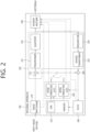
- the inter predictor 221 may configure a motion information candidate list based on neighboring blocks and generate information indicating which candidate is used to derive a motion vector and/or a reference picture index of the current block. Inter prediction may be performed based on various prediction modes. For example, in the case of a skip mode and a merge mode, the inter predictor 221 may use motion information of the neighboring block as motion information of the current block.
- the predictor 220 may generate a prediction signal based on various prediction methods. For example, the predictor may apply intra prediction or inter prediction for prediction on one block, and, as well, may apply intra prediction and inter prediction at the same time. This may be called combined inter and intra prediction (CIIP).Further, the predictor may be based on an intra block copy (IBC) prediction mode, or a palette mode in order to perform prediction on a block.
- IBC intra block copy
- palette mode may be used for content image/video coding of a game or the like, such as screen content coding (SCC).Although the IBC basically performs prediction in a current block, it can be performed similarly to inter prediction in that it derives a reference block in a current block. That is, the IBC may use at least one of inter prediction techniques described in the present disclosure.
- the video/image information may further include information on various parameter sets such as an adaptation parameter set (APS), a picture parameter set (PPS), a sequence parameter set (SPS), a video parameter set (VPS) or the like. Further, the video/image information may further include general constraint information.
- information and/or syntax elements which are transmitted/signaled to the decoding apparatus from the encoding apparatus may be included in video/image information.
- the video/image information may be encoded through the above-described encoding procedure and included in the bitstream.
- the bitstream may be transmitted through a network, or stored in a digital storage medium.
- the network may include a broadcast network, a communication network and/or the like
- the digital storage medium may include various storage media such as USB, SD, CD, DVD, Blu-ray, HDD, SSD, and the like.
- a transmitter (not shown) which transmits a signal output from the entropy encoder 240 and/or a storage (not shown) which stores it may be configured as an internal/external element of the encoding apparatus 200, or the transmitter may be included in the entropy encoder 240.
- Quantized transform coefficients output from the quantizer 233 may be used to generate a prediction signal. For example, by applying dequantization and inverse transform to quantized transform coefficients through the dequantizer 234 and the inverse transformer 235, the residual signal (residual block or residual samples) may be reconstructed.
- the adder 155 adds the reconstructed residual signal to a prediction signal output from the inter predictor 221 or the intra predictor 222, so that a reconstructed signal (reconstructed picture, reconstructed block, reconstructed sample array) may be generated.
- the predicted block may be used as a reconstructed block.
- the adder 250 may be called a reconstructor or a reconstructed block generator.
- the generated reconstructed signal may be used for intra prediction of a next processing target block in the current block, and as described later, may be used for inter prediction of a next picture through filtering.
- LMCS luma mapping with chroma scaling
- the filter 260 may improve subjective/objective video quality by applying the filtering to the reconstructed signal.
- the filter 260 may generate a modified reconstructed picture by applying various filtering methods to the reconstructed picture, and may store the modified reconstructed picture in the memory 270, specifically in the DPB of the memory 270.
- the various filtering methods may include, for example, deblocking filtering, sample adaptive offset, an adaptive loop filter, a bilateral filter or the like.
- the filter 260 may generate various information relating to filtering, and transmit the generated information to the entropy encoder 240.
- the information on the filtering may be encoded in the entropy encoder 240 and output in the form of a bitstream.
- the memory 270 DPB may store the modified reconstructed picture in order to use it as a reference picture in the inter predictor 221.
- the memory 270 may store motion information of a block in the current picture, from which motion information has been derived (or encoded) and/or motion information of blocks in an already reconstructed picture.
- the stored motion information may be transmitted to the inter predictor 221 to be utilized as motion information of a neighboring block or motion information of a temporal neighboring block.
- the memory 270 may store reconstructed samples of reconstructed blocks in the current picture, and transmit them to the intra predictor 222.
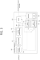
- FIG. 3 is a diagram schematically illustrating a configuration of a video/image decoding apparatus to which the present disclosure is applicable.
- the video decoding apparatus 300 may include an entropy decoder 310, a residual processor 320, a predictor 330, an adder 340, a filter 350 and a memory 360.
- the predictor 330 may include an inter predictor 331 and an intra predictor 332.
- the residual processor 320 may include a dequantizer 321 and an inverse transformer 321.
- the entropy decoder 310, the residual processor 320, the predictor 330, the adder 340, and the filter 350 which have been described above, may be constituted by one or more hardware components (e.g., decoder chipsets or processors) according to an embodiment.
- the memory 360 may include a decoded picture buffer (DPB), and may be constituted by a digital storage medium.
- the hardware component may further include the memory 360 as an internal/external component.
- the decoding apparatus 300 may reconstruct an image correspondingly to a process by which video/image information has been processed in the encoding apparatus of FIG. 2 .
- the decoding apparatus 300 may derive units/blocks based on information relating to block partition obtained from the bitstream.
- the decoding apparatus 300 may perform decoding by using a processing unit applied in the encoding apparatus. Therefore, the processing unit of decoding may be, for example, a coding unit, which may be partitioned along the quad-tree structure, the binary-tree structure, and/or the ternary-tree structure from a coding tree unit or a largest coding unit.
- One or more transform units may be derived from the coding unit.
- the reconstructed image signal decoded and output through the decoding apparatus 300 may be reproduced through a reproducer.
- signaled/received information and/or syntax elements may be decoded through the decoding procedure and be obtained from the bitstream.
- the entropy decoder 310 may decode information in the bitstream based on a coding method such as exponential Golomb encoding, CAVLC, CABAC, or the like, and may output a value of a syntax element necessary for image reconstruction and quantized values of a transform coefficient regarding a residual.
- a CABAC entropy decoding method may receive a bin corresponding to each syntax element in a bitstream, determine a context model using decoding target syntax element information and decoding information of neighboring and decoding target blocks, or information of symbol/bin decoded in a previous step, predict bin generation probability according to the determined context model and perform arithmetic decoding of the bin to generate a symbol corresponding to each syntax element value.
- the CABAC entropy decoding method may update the context model using information of a symbol/bin decoded for a context model of the next symbol/bin after determination of the context model.
- a receiver which receives a signal output from the encoding apparatus may further constitute the decoding apparatus 300 as an internal/external element, and the receiver may be a component of the entropy decoder 310.
- the decoding apparatus according to the present disclosure may be called a video/image/picture coding apparatus, and the decoding apparatus may be classified into an information decoder (video/image/picture information decoder) and a sample decoder (video/image/picture sample decoder).
- the information decoder may include the entropy decoder 310, and the sample decoder may include at least one of the dequantizer 321, the inverse transformer 322, the adder 340, the filter 350, the memory 360, the inter predictor 332, and the intra predictor 331.
- the dequantizer 321 may output transform coefficients by dequantizing the quantized transform coefficients.
- the dequantizer 321 may rearrange the quantized transform coefficients in the form of a two-dimensional block. In this case, the rearrangement may perform rearrangement based on an order of coefficient scanning which has been performed in the encoding apparatus.
- the dequantizer 321 may perform dequantization on the quantized transform coefficients using quantization parameter (e.g., quantization step size information), and obtain transform coefficients.
- quantization parameter e.g., quantization step size information
- the predictor may generate a prediction signal based on various prediction methods. For example, the predictor may apply intra prediction or inter prediction for prediction on one block, and, as well, may apply intra prediction and inter prediction at the same time. This may be called combined inter and intra prediction (CIIP).
- the predictor may perform intra block copy (IBC) for prediction on a block.
- the intra block copy may be used for content image/video coding of a game or the like, such as screen content coding (SCC).Although the IBC basically performs prediction in a current block, it can be performed similarly to inter prediction in that it derives a reference block in a current block. That is, the IBC may use at least one of inter prediction techniques described in the present disclosure.
- the inter predictor 332 may configure a motion information candidate list based on neighboring blocks, and derive a motion vector and/or a reference picture index of the current block based on received candidate selection information.
- Inter prediction may be performed based on various prediction modes, and the information on prediction may include information indicating a mode of inter prediction for the current block.
- the adder 340 may be called a reconstructor or a reconstructed block generator.
- the generated reconstructed signal may be used for intra prediction of a next processing target block in the current block, and as described later, may be output through filtering or be used for inter prediction of a next picture.
- LMCS luma mapping with chroma scaling
- the streaming server may receive contents from the media storage and/or the encoding server. For example, in a case the contents are received from the encoding server, the contents may be received in real time. In this case, the streaming server may store the bitstream for a predetermined period of time to provide the streaming service smoothly.
- the user equipment may include a mobile phone, a smart phone, a laptop computer, a digital broadcasting terminal, a personal digital assistant (PDA), a portable multimedia player (PMP), a navigation, a slate PC, a tablet PC, an ultrabook, a wearable device (e.g., a watch-type terminal (smart watch), a glass-type terminal (smart glass), a head mounted display (HMD)), a digital TV, a desktop computer, a digital signage or the like.
- PDA personal digital assistant
- PMP portable multimedia player
- HMD head mounted display
- Each of servers in the contents streaming system may be operated as a distributed server, and in this case, data received by each server may be processed in distributed manner.
- FIG. 5 schematically illustrates a multiple transform technique according to an embodiment of the present disclosure.
- the transformer may derive (primary) transform coefficients by performing a primary transform based on residual samples (residual sample array) in a residual block (S510).
- This primary transform may be referred to as a core transform.
- the primary transform may be based on multiple transform selection (MTS), and when a multiple transform is applied as the primary transform, it may be referred to as a multiple core transform.
- MTS multiple transform selection
- a vertical transform kernel and a horizontal transform kernel for a target block may be selected from among the transform kernels, a vertical transform for the target block may be performed based on the vertical transform kernel, and a horizontal transform for the target block may be performed based on the horizontal transform kernel.
- the horizontal transform may represent a transform for horizontal components of the target block
- the vertical transform may represent a transform for vertical components of the target block.
- the vertical transform kernel/horizontal transform kernel may be adaptively determined based on a prediction mode and/or a transform index of a target block (CU or sub-block) including a residual block.
- a mapping relationship for transform kernels may be set by setting specific basis functions to predetermined values and combining basis functions to be applied in the vertical transform or the horizontal transform.
- a trTypeHor or trTypeVer value of 0 may be set to DCT2
- a trTypeHor or trTypeVer value of 1 may be set to DST-7
- a trTypeHor or trTypeVer value of 2 may be set to DCT-8.
- MTS index information may be encoded and signaled to the decoding apparatus to indicate any one of a plurality of transform kernel sets.
- an MTS index of 0 may indicate that both trTypeHor and trTypeVer values are 0
- an MTS index of 1 may indicate that both trTypeHor and trTypeVer values are 1
- an MTS index of 2 may indicate that the trTypeHor value is 2 and the trTypeVer value.
- Is 1 an MTS index of 3 may indicate that the trTypeHor value is 1 and the trTypeVer value is 2
- an MTS index of 4 may indicate that both both trTypeHor and trTypeVer values are 2.
- transform kernel sets according to MTS index information are illustrated in the following table.
- the transformer may derive modified (secondary) transform coefficients by performing the secondary transform based on the (primary) transform coefficients (S520).
- the primary transform is a transform from a spatial domain to a frequency domain, and the secondary transform refers to transforming into a more compressive expression by using a correlation existing between (primary) transform coefficients.
- the secondary transform may include a non-separable transform.
- the secondary transform may be called a non-separable secondary transform (NSST), or a mode-dependent non-separable secondary transform (MDNSST).
- the non-separable secondary transform may represent a transform method in which is not separately applied in the vertical direction and the horizontal direction for the (primary) transform coefficients, and for example, two-dimensional signals (transform coefficients) are re-arranged to a one-dimensional signal through a certain determined direction (e.g., row-first direction or column-first direction), and then modified transform coefficients (or secondary transform coefficients) are generated based on the non-separable transform matrix.
- a certain determined direction e.g., row-first direction or column-first direction
- modified transform coefficients or secondary transform coefficients
- M x N blocks are disposed in a line in an order of a first row, a second row, ..., and an Nth row.
- the non-separable secondary transform may be performed as follows.
- the 4x4 input block X may be represented as follows.
- X X 00 X 01 X 02 X 03 X 10 X 11 X 12 X 13 X 20 X 21 X 22 X 23 X 30 X 31 X 32 X 33
- the vector X ⁇ may be represented as below.
- X ⁇ X 00 X 01 X 02 X 03 X 10 X 11 X 12 X 13 X 20 X 21 X 22 X 23 X 30 X 31 X 32 X 33 T
- the vector X ⁇ is a one-dimensional vector obtained by rearranging the two-dimensional block X of Equation 1 according to the row-first order.
- the secondary non-separable transform may be calculated as below.
- F ⁇ T ⁇ X ⁇
- F ⁇ represents a transform coefficient vector
- T represents a 16x16 (non-separable) transform matrix
- a 16x1 transform coefficient vector F ⁇ may be derived, and the F ⁇ may be re-organized into a 4x4 block through a scan order (horizontal, vertical, diagonal and the like).
- the above-described calculation is an example, and hypercube-Givens transform (HyGT) or the like may be used for the calculation of the non-separable secondary transform in order to reduce the computational complexity of the non-separable secondary transform.
- a transform kernel (or transform core, transform type) may be selected to be mode dependent.
- the mode may include the intra prediction mode and/or the inter prediction mode.
- the non-separable secondary transform may be performed based on an 8x8 transform or a 4x4 transform determined based on the width (W) and the height (H) of the transform coefficient block.
- the 8x8 transform refers to a transform that is applicable to an 8x8 region included in the transform coefficient block when both W and H are equal to or greater than 8, and the 8x8 region may be a top-left 8x8 region in the transform coefficient block.
- the 4x4 transform refers to a transform that is applicable to a 4x4 region included in the transform coefficient block when both W and H are equal to or greater than 4, and the 4x4 region may be a top-left 4x4 region in the transform coefficient block.
- an 8x8 transform kernel matrix may be a 64x64/16x64 matrix
- a 4x4 transform kernel matrix may be a 16x16/8x16 matrix.
- two non-separable secondary transform kernels per transform set for a non-separable secondary transform may be configured for both the 8 x 8 transform and the 4x4 transform, and there may be four transform sets. That is, four transform sets may be configured for the 8 x 8 transform, and four transform sets may be configured for the 4x4 transform.
- each of the four transform sets for the 8 x 8 transform may include two 8 x 8 transform kernels
- each of the four transform sets for the 4x4 transform may include two 4x4 transform kernels.
- the size of the transform that is, the size of a region to which the transform is applied, may be, for example, a size other than 8 x 8 or 4 x 4, the number of sets may be n, and the number of transform kernels in each set may be k.
- the transform set may be referred to as an NSST set or an LFNST set.
- a specific set among the transform sets may be selected, for example, based on the intra prediction mode of the current block (CU or subblock).
- a low-frequency non-separable transform (LFNST) may be an example of a reduced non-separable transform, which will be described later, and represents a non-separable transform for a low frequency component.
- the intra prediction mode may include two non-directinoal (or non-angular) intra prediction modes and 65 directional (or angular) intra prediction modes.
- the non-directional intra prediction modes may include a planar intra prediction mode of No. 0 and a DC intra prediction mode of No. 1, and the directional intra prediction modes may include 65 intra prediction modes of Nos. 2 to 66.
- this is an example, and this document may be applied even when the number of intra prediction modes is different.
- intra prediction mode No. 67 may be further used, and the intra prediction mode No. 67 may represent a linear model (LM) mode.
- LM linear model
- FIG. 6 exemplarily shows intra directional modes of 65 prediction directions.
- intra prediction mode 34 on the basis of intra prediction mode 34 having a left upward diagonal prediction direction, the intra prediction modes may be divided into intra prediction modes having horizontal directionality and intra prediction modes having vertical directionality.
- H and V denote horizontal directionality and vertical directionality, respectively, and numerals -32 to 32 indicate displacements in 1/32 units on a sample grid position. These numerals may represent an offset for a mode index value.
- Intra prediction modes 2 to 33 have the horizontal directionality
- intra prediction modes 34 to 66 have the vertical directionality. Strictly speaking, intra prediction mode 34 may be considered as being neither horizontal nor vertical, but may be classified as belonging to the horizontal directionality in determining a transform set of a secondary transform.
- Intra prediction mode 18 and intra prediction mode 50 may represent a horizontal intra prediction mode and a vertical intra prediction mode, respectively, and intra prediction mode 2 may be referred to as a right upward diagonal intra prediction mode because intra prediction mode 2 has a left reference pixel and performs prediction in a right upward direction.
- intra prediction mode 34 may be referred to as a right downward diagonal intra prediction mode
- intra prediction mode 66 may be referred to as a left downward diagonal intra prediction mode.
- the four transform sets according to the intra prediction mode may be mapped, for example, as shown in the following table.
- lfnst index value 0 may refer to a first non-separable secondary transform kernel
- lfnst index value 1 may refer to a second non-separable secondary transform kernel
- lfnst index value 2 may refer to a third non-separable secondary transform kernel.
- lfnst index value 0 may indicate that the first non-separable secondary transform is not applied to the target block
- lfnst index values 1 to 3 may indicate the three transform kernels.
- RST may be referred to as various terms, such as reduced transform, reduced secondary transform, reduction transform, simplified transform, simple transform, and the like, and the name which RST may be referred to as is not limited to the listed examples.
- the RST since the RST is mainly performed in a low frequency region including a non-zero coefficient in a transform block, it may be referred to as a Low-Frequency Non-Separable Transform (LFNST).
- LFNST Low-Frequency Non-Separable Transform
- the transform index may be referred to as an LFNST index.
- FIG. 7 is a diagram illustrating an RST according to an embodiment of the present disclosure.
- an N-dimensional vector may be mapped to an R-dimensional vector located in another space, so that the reduced transform matrix may be determined, where R is less than N.
- N may mean the square of the length of a side of a block to which the transform is applied, or the total number of transform coefficients corresponding to a block to which the transform is applied, and the reduced factor may mean an R/N value.
- the reduced factor may be referred to as a reduced factor, reduction factor, simplified factor, simple factor or other various terms.
- R may be referred to as a reduced coefficient, but according to circumstances, the reduced factor may mean R. Further, according to circumstances, the reduced factor may mean the N/R value.
- a matrix operation may be understood as an operation of multiplying a column vector by a matrix, disposed on the left of the column vector, to obtain a column vector.
- the size of the inverse RST matrix T NxR according to an example is NxR less than the size N x N of the regular inverse transform matrix, and is in a transpose relationship with the reduced transform matrix T RxN shown in Equation 4.
- index 0 may be allocated to a case where an identity matrix is applied, that is, a case where no secondary transform is applied
- a transform index or an lfnst index as a syntax element may be signaled for each transform coefficient block, thereby designating a transform to be applied. That is, for a top-left 8 x 8 block, through the transform index, it is possible to designate an 8 x 8 RST in an RST configuration, or to designate an 8 x 8 lfnst when the LFNST is applied.
- the 8 x 8 lfnst and the 8 x 8 RST refer to transforms applicable to an 8 x 8 region included in the transform coefficient block when both W and H of the target block to be transformed are equal to or greater than 8, and the 8 x 8 region may be a top-left 8 x 8 region in the transform coefficient block.
- a 4 x 4 lfnst and a 4 x 4 RST refer to transforms applicable to a 4 x 4 region included in the transform coefficient block when both W and H of the target block to are equal to or greater than 4, and the 4 x 4 region may be a top-left 4x4 region in the transform coefficient block.
- a 48 x 1 vector may be constructed based on 48 pieces of data constituting a region excluding the bottom right 4x4 region among the 8 x 8 regions.
- the transposed matrix of the foregoing transform kernel matrix may be used. That is, when an inverse RST or LFNST is performed in the inverse transform process performed by the decoding apparatus, input coefficient data to which the inverse RST is applied is configured in a one-dimensional vector according to a predetermined arrangement order, and a modified coefficient vector obtained by multiplying the one-dimensional vector and a corresponding inverse RST matrix on the left of the one-dimensional vector may be arranged in a two-dimensional block according to a predetermined arrangement order.
- a matrix operation of 48 transform coefficients in top-left, top-right, and bottom-left regions of the 8x8 region excluding the bottom-right region among transform coefficients in the 8 x 8 region and a 16 x 48 transform kernel matrix For the matrix operation, the 48 transform coefficients are input in a one-dimensional array. When the matrix operation is performed, 16 modified transform coefficients are derived, and the modified transform coefficients may be arranged in the top-left region of the 8 x 8 region.
- an n x 1 vector may be interpreted to have the same meaning as an n x 1 matrix and may thus be expressed as an nx1 column vector.
- * denotes matrix multiplication.
- 48 modified transform coefficients may be derived, and the 48 modified transform coefficients may be arranged in top-left, top-right, and bottom-left regions of the 8x8 region excluding a bottom-right region.
- the inverse transformer 235 of the encoding apparatus 200 and the inverse transformer 322 of the decoding apparatus 300 may include an inverse reduced secondary transformer to derive modified transform coefficients based on an inverse RST on transform coefficients and an inverse primary transformer to derive residual samples for the target block based on an inverse primary transform on the modified transform coefficients.
- the inverse primary transform refers to the inverse transform of a primary transform applied to a residual.
- deriving a transform coefficient based on a transform may refer to deriving the transform coefficient by applying the transform.
- the above-described non-separated transform, the LFNST will be described in detail as follows.
- the LFNST may include a forward transform by the encoding apparatus and an inverse transform by the decoding apparatus.
- the encoding apparatus receives a result (or a part of a result) derived after applying a primary (core) transform as an input, and applies a forward secondary transform (secondary transform).
- y G T x
- the dimensions of matrix G are [ 48 x 16 ], [ 48 x 8 ], [ 16 x 16 ], [16 x 8 ], and the [ 48 x 8 ] matrix and the [ 16 x 8 ] matrix are partial matrices that sampled 8 transform basis vectors from the left of the [ 48 x 16 ] matrix and the [ 16 x 16 ] matrix, respectively.
- the dimensions of matrix G T are [ 16 x 48 ], [ 8 x 48 ], [ 16 x 16 ], [ 8 x 16 ], and the [ 8 x 48 ] matrix and the [ 8 x 16 ] matrix are partial matrices obtained by sampling 8 transform basis vectors from the top of the [16 x 48 ] matrix and the [ 16 x 16 ] matrix, respectively.
- a [ 48 x 1 ] vector or [ 16 x 1 ] vector is possible as an input x
- a [ 16 x 1 ] vector or a [ 8 x 1 ] vector is possible as an output y.
- the output of the forward primary transform is two-dimensional (2D) data, so to construct the [ 48 x 1 ] vector or the [ 16 x 1 ] vector as the input x, a one-dimensional vector must be constructed by properly arranging the 2D data that is the output of the forward transformation.
- FIG. 8 is a diagram illustrating a sequence of arranging output data of a forward primary transformation into a one-dimensional vector according to an example.
- the left diagrams of (a) and (b) of FIG. 8 show the sequence for constructing a [ 48 x 1 ] vector, and the right diagrams of (a) and (b) of FIG. 8 shows the sequence for constructing a [ 16 x 1 ] vector.
- a one-dimensional vector x can be obtained by sequentially arranging 2D data in the same order as in (a) and (b) of FIG. 8 .
- Equation 9 Since the output y derived through Equation 9 is a one-dimensional vector, when two-dimensional data is required as input data in the process of using the result of the forward secondary transformation as an input, for example, in the process of performing quantization or residual coding, the output y vector of Equation 9 must be properly arranged as 2D data again.
- one of 8 [ 48 x 16 ] matrices and 8 [ 16 x 16 ] matrices may be selected as the transformation matrix G. Whether to apply the [ 48 x 16 ] matrix or the [ 16 x 16 ] matrix depends on the size and shape of the block.
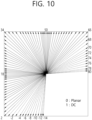
- FIG. 10 is a diagram illustrating wide-angle intra prediction modes according to an embodiment of the present document.
- the wide-angle intra prediction When the wide-angle intra prediction is applied, information on the existing intra prediction may be signaled, and after the information is parsed, the information may be remapped to the index of the wide-angle intra prediction mode. Therefore, the total number of the intra prediction modes for a specific block (eg, a non-square block of a specific size) may not change, and that is, the total number of the intra prediction modes is 67, and intra prediction mode coding for the specific block may not be changed.
- a specific block eg, a non-square block of a specific size
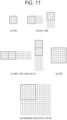
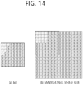
- the [ 16 x 8] matrix is applied to the 4x4 block (4x4 TU or 4x4 CU) of FIG. 11 (a) and the [ 16 x 16 ] matrix is applied to the blocks in (b) and (c) of FIG. 11 . This is to adjust the computational complexity for the worst case to 8 multiplications per sample.
- the LFNST is applied to the top-left 8x8 region, and this LFNST is hereinafter referred to as "8x8 LFNST".
- 8x8 LFNST As a corresponding transformation matrix, a [ 48 x 16 ] matrix or [ 48 x 8 ] matrix may be applied.
- the [48 x 1] vector (x vector in Equation 9) is input as input data, all sample values of the top-left 8x8 region are not used as input values of the forward LFNST. That is, as can be seen in the left order of FIG. 8 (a) or the left order of FIG. 8 (b) , the [48 x 1] vector may be constructed based on samples belonging to the remaining 3 4x4 blocks while leaving the bottom-right 4x4 block as it is.
- the [ 48 x 8 ] matrix may be applied to an 8 ⁇ 8 block (8 ⁇ 8 TU or 8 ⁇ 8 CU) in FIG. 11 (d) , and the [48 ⁇ 16] matrix may be applied to the 8 ⁇ 8 block in FIG. 11(e) . This is also to adjust the computational complexity for the worst case to 8 multiplications per sample.
- 8 or 16 output data (y vector in Equation 9, [ 8 x 1 ] or [ 16 x 1 ] vector) is generated.
- the number of output data is equal to or less than the number of input data due to the characteristics of the matrix G T .
- FIG. 12 is a diagram illustrating an arrangement of output data of a forward LFNST according to an example, and shows a block in which output data of the forward LFNST is arranged according to a block shape.
- the shaded area at the top-left of the block shown in FIG. 12 corresponds to the area where the output data of the forward LFNST is located, the positions marked with 0 indicate samples filled with 0 values, and the remaining area represents regions that are not changed by the forward LFNST. In the area not changed by the LFNST, the output data of the forward primary transform remains unchanged.
- the output data of the forward LFNST may not completely fill the top-left 4x4 block.
- a [ 16 x 8 ] matrix and a [ 48 x 8 ] matrix are applied to the block indicated by a thick line or a partial region inside the block, respectively, and a [ 8 x 1 ] vector as the output of the forward LFNST is generated. That is, according to the scan order shown in (b) of FIG. 9 , only 8 output data may be filled as shown in (a) and (d) of FIG.
- the encoding apparatus may know whether there is the non-zero data (significant coefficients) for all positions within the TU or CU block through the residual coding. Accordingly, the encoding apparatus may determine whether to perform signaling on the LFNST index based on the existence of the non-zero data, and the decoding apparatus may determine whether the LFNST index is parsed. When the non-zero data does not exist in the area designated in 1) and 2) above, signaling of the LFNST index is performed.
- the following simplification methods may be applied.
- the whole region to which the LFNST is not applied may be filled with zeros.
- the area filled with zeros may be not same when the LFNST is applied. Accordingly, it is possible to check whether the non-zero data exists according to the zero-out proposed in (ii) over a wider area than the case of the LFNST of FIG. 12 .
- signaling for the LFNST index can be performed only when the non-zero data does not exist.
- the encoding apparatus only performs the zero out and the decoding apparatus does not assume the zero out, that is, checking only whether the non-zero data exists only in the area explicitly marked as 0 in FIG. 12 , may perform the LFNST index parsing.
- the LFNST when the LFNST is applied, after checking whether the non-zero data exists in a position where the residual coding process is not allowed (at a position beyond the last position), it can be determined whether the LFNST index is signaled.
- the secondary transformation such as the LFNST adds a computational amount to the existing primary transformation, thus increasing the overall delay time involved in performing the transformation.
- an increase in latency due to a secondary transformation leads to an increase in latency until reconstruction. This can lead to an increase in overall latency of intra prediction encoding.
- one coding block may be partitioned into two or four sub-blocks and be coded, and in the ISP, intra prediction is performed on one sub-block by referring to the reconstructed pixel value of a sub-block located adjacent to the left or top side thereof.
- coding may be used as a concept including both coding performed by the encoding apparatus and decoding performed by the decoding apparatus.
- the LFNST index may be transmitted only when both the horizontal length and the vertical length of the coding unit are equal to or greater than 4.
- the corresponding LNFST index may be transmitted.
- the length condition is independently viewed for the horizontal direction and the vertical direction, and DST-7 is applied instead of DCT-2 without signaling for the MTS index. It is determined whether or not the horizontal or vertical length is greater than or equal to 4 and less than or equal to 16, and a primary transform kernel is determined according to the determination result. Accordingly, in the case of the ISP mode, when the LFNST can be applied, the following transform combination configuration is possible.
- image information may be configured such that the LFNST index is transmitted for each partition block rather than for each coding unit.
- LFNST index signaling method it may be regarded that only one partition block exists in a unit in which the LFNST index is transmitted, and it may be determined whether or not to signal the LFNST index.
- a block When a block is predicted by applying BDPCM, reconstructed samples are used to predict a row or column of a block line by line.
- used reference pixels may be unfiltered samples.
- a BDPCM direction may indicate whether a vertical direction or a horizontal direction prediction is used.
- a prediction error is quantized in a spatial domain, and a pixel is reconstructed by adding a dequantized prediction error to a prediction.
- a quantized residual domain BDPCM may be proposed, in which a prediction direction or signaling may be the same as that in the BDPCM applied to the spatial domain.
- whether to apply a block-based delta pulse code modulation (BDPCM) mode may be signaled in a syntax table for a coding unit as shown in Table 3.
- intra_bdpcm_luma_flag 1 specifies that BDPCM is applied to the current luma coding block at the location (x0, y0 ), i.e. the transform is skipped, the intra luma prediction mode is specified by intra_bdpem_luma_dir_flag.
- intra_bdpcm_luma_flag 0 specifies that BDPCM is not applied to the current luma coding block at the location ( x0, y0 ). When intra_bdpcm_luma_flag is not present it is inferred to be equal to 0.
- intra_bdpcm_chroma_flag 0 specifies that BDPCM is not applied to the current chroma coding blocks at the location ( x0, y0 ).
- intra_bdpcm_chroma_flag not present it is inferred to be equal to 0.
- intra_bdpcm_chroma_dir_flag 0 specifies that the BDPCM prediction direction is horizontal.
- intra_bdpcm_chroma_dir_flag 1 specifies that the BDPCM prediction direction is vertical.
- BdpcmFlag[ x ][ y ][ cIdx ] of Table 4 the value of x is an x-coordinate (horizontal pixel position) value based on a top-left horizontal coordinate (x-coordinate) position of a luma picture as a reference (set to 0), and x-coordinates increase from left to right.
- the value of y is a y-coordinate (vertical pixel position) value based on a top-left vertical coordinate (y-coordinate) position of the luma picture as a reference (set to 0), and y-coordinates increase from top to bottom.
- a horizontal resolution of the chroma component is twice lower than that of the luma component (e.g., when a color format for the picture is 4:2:0 or 4:2:2)
- actual x-coordinate values for a chroma picture is half the corresponding coordinates based on the luma picture.
- cbWidth and cbHeight respectively indicate the width and length of the coding block based on the luma component.
- the horizontal (vertical) resolution of the chroma component is twice lower than that of the luma component
- the actual width (length) of the corresponding chroma coding block is half that of the luma coding block.
- x0 and y0 respectively indicate an x-coordinate value and a y-coordinate value of the top-left position in the luma coding block when the top-left position of the luma picture is set to 0.
- the chroma coding block corresponds to a collocated luma position when converted into a luma component.
- BDPCM may be applied to both of the two chroma components (Cb and Cr) of the coding unit currently coded.
- transform skip _flag a transform skip flag for the component
- transform_skip_flag [ x0 ][ y0 ][ cIdx ] specifies whether a transform is applied to the associated transform block or not
- the array indices x0, y0 specify the location ( x0, y0 ) of the top-left luma sample of the considered transform block relative to the top-left luma sample of the picture.
- the array index cIdx specifies an indicator for the colour component, it is equal to 0 for Y, 1 for Cb, and 2 for Cr.
- transform_skip_flag[ x0 ][ y0 ][ cIdx ] 1 specifies that no transform is applied to the associated transform block.
- transform_skip_flag[ x0 ][ y0 ][ cIdx ] 0 specifies that the decision whether transform is applied to the associated transform block or not depends on other syntax elements.
- transform_skip_flag[ x0 ][ y0 ][ cIdx ] When transform_skip_flag[ x0 ][ y0 ][ cIdx ] is not present it is inferred as follows: - If BdpcmFlag[ x0 ][ y0 ][ cIdx ] is equal to 1, transform_skip_flag[ x0 ][ y0 ][ cIdx ] is inferred to be equal to 1. - Otherwise (BdpcmFlag[ x0 ][ y0 ][ cIdx ] is equal to 0), transform_skip_flag[ x0 ][ y0 ][ cIdx ] is inferred to be equal to 0. ...
- transform skip flag[x0] [y0] [cIdx] is a flag indicating whether the coding block is coded with a transform skip.
- a flag value of 1 indicates that the transform skip is applied, and a flag value of 0 indicates that the transform skip is not applied.
- x0, y0, and cIdx are also specified in Table 5 and have been described with reference to Table 4.
- Table 6 is a syntax table for a transform unit, which shows signaling or parsing of transform_skip_flag[x0] [y0] [cIdx] and a coded block flag (CBF) value of a transform block for each color component.
- CBF coded block flag
- a coded block flag indicates whether a transform coefficient exists in the transform block, in which a value of 1 indicates that a transform coefficient exists and a value of 0 indicates that a transform coefficient does not exist. Therefore, even though BDPCM is applied to each component, a corresponding CBF value may be 0.
- a residual signal is reconstructed by accumulating values transmitted in the form of transform coefficients for each position according to a selected direction (the horizontal or vertical direction in VVC, specified by intra bdpcm luma dir_flag for the luma component in Table 4, and specified by intra bdpm chroma _dir flag for the chroma component).
- a CBF value of 0 may be regarded as the same in terms of operation as in a general intra prediction method without a residual signal.
- the BDPCM mode of signaling intra bdpcm luma flag, intra_bdpcm_luma_dir _flag, intra_bdpcm_chroma_flag, and intra_bdpcm_chroma_dir_flag as shown in Table 3 may be more advantageous than intra prediction coding in terms of RD cost. Therefore, when the CBF value is 0, coding may be performed in the BDPCM mode, and therefore there may exist a case where the CBF value is 0 even in the BDPCM mode.
- An LFNST index (lmst_idx) may be signaled in the coding unit of Table 3, and as shown in Table 3, the LFNST index may be signaled only when the value of the variable lfnstNotTsFlag is 1.
- the value of lfnstNotTsFlag is set to 1. That is, the variable IfnstNotTsFlag may be set to 1 only when all of transform skip flag values for all components belonging to the current coding unit are 0.
- the value of lfnstNotTsFlag may be 1 only when transform skip flags for both the luma component and the chroma component are 0, in a luma separate tree (DUAL _TREE _LUMA), the value of the variable lfnstNotTsFlag may be 1 when only a transform skip flag for the luma component is 0, and in a chroma separate tree (DUAL TREE CHROMA), the value of variable the lfnstNotTsFlag may be 1 only when all transform skip flags for the Cb component and the Cr component are 0.
- a transform skip flag for the component may be inferred to 1.
- the component is irrelevant to the transform process.
- the component is irrelevant to the transform process and thus needs to be irrelevant to signaling of the LFNST index.
- the transform skip flag for the component is inferred to 1 and thus the value of lfnstNotTsFlag is set to 0, the LFNST index is not signaled. For specific illustration, the following cases may be illustrated.
- the LFNST may be applied to the remaining component, and thus it is desirable to allow signaling the LFNST index.
- the LFNST may be applied to the component(s), and thus it is desirable to allow signaling the LFNST index.
- BDPCM is applied to the luma component (Y) is determined by intra luma bdpcm flag (when the value of intra_luma_bdpcm_flag is 1, BDPCM is applied, and when the value of intra luma bdpcm flag is 0, BDPCM is not applied) and whether BDPCM is applied to the two chroma components (Cb and Cr) is determined by intra_chroma_bdpcm_flag (when the value of intra_chroma_bdpcm_flag is 1, BDPCM is applied, and when the value of intra _chroma_bdpcm_flag is 0, BDPCM is not applied).
- the LFNST may be applied to the chroma component(s).
- the LFNST index can be signaled only when all of the transform skip flag values for the two chroma components are 0 in the current VVC standard, and to this end, BDPCM may not be applied to the two chroma components.
- the LFNST is not applied to the chroma components when coding is performed in the single tree.
- the LFNST index may be signaled in the two cases ((1) and (2)).
- tu_y_coded_flag[ x0 ][ y0 ] or transform_skip_flag[ x0 ][ y0 ][ 0 ] needs to be inferred to 0.
- the LFNST may be applied to a coding block to which the ISP mode is applied.
- the ISP mode When the ISP mode is applied in the current VVC standard, it is guaranteed that at least one of the partition blocks has a CBF of 1, and one of the partition blocks having a CBF of 1 does not necessarily need to be a first partition block in coding order.
- tu y coded flag[ x0 ] [ y0 ] in Table 7 and Table 8 is a CBF for the first partition block.
- Table 7 and Table 8 may be described as Table 9 and Table 10, respectively, to reflect a situation in which it is impossible to clearly check whether a transform coefficient exists in the luma coding block.
- the LFNST 1) may be applied in the luma separate tree, 2) may be applied in the chroma separate tree, and 3) may be applied only to the luma component in the single tree.
- the component since a transform is not applied to a component which BDPCM is applied to and which has a CBF of 0, the component may be considered to be irrelevant to the LFNST.
- lfnstNotTsFlag may be derived as shown in Table 11 or Table 12 without checking the CBF value for the luma component.
- the LFNST may be applied only to the luma component.
- the CBF value for the luma component is 0, the value of the variable LfnstDcOnly value is maintained as 1 in Table 3, and thus the LFNST index is inferred to 0 without being signaled.
- the LFNST index is signaled, the CBF value for the luma component is 0, and consequently the LFNST is not applied to any component, and thus the LFNST index may be redundantly signaled.
- the LFNST index may be configured to be inferred to 0 without being signaled when the CBF value for the luma component is 0 in the single tree.
- variable lfnstNotTsFlag may be set as shown in the Table 14.
- the LFNST index is signaled only when the CBF value for the luma component is 1 the same as in Table 3, and 2) in the chroma separate tree, the LFNST index is not signaled when all of the CBF values for the chroma components (Cb and Cr) are 0 as in Table 7 to Table 12, for example, when BDPCM is applied and all of the CBF values for the Cb component and the Cr component are 0.
- the LFNST index may be signaled when the CBF value for the luma component is 1 and 3-1) the transform skip is not applied to both the Cb component and the Cr component or 3-2) all of the CBF values for the Cb component and the Cr component are 0 when BDPCM is applied to the chroma component.
- the LFNST index signaling method presented in Table 3 that is, the existing setting for the variable lfnstNotTsFlag, may be used to as it is by inferring a CBF value for the component as 1.
- the syntax table for the transform unit of Table 6 may be changed as shown in Table 15.
- intra subpartitions_mode_flag[ x0 ][ y0 ] may be parsed only when intra bdpcm luma flag is 0, ISP is not enabled when BDPCM is enabled, and BDPCM is not enabled when ISP is enabled.
- tu_cb_coded_flag[ x0 ][ y0 ] When tu_cb_coded_flag[ x0 ][ y0 ] is not present, its value is inferred as follows: - If BdpcmFlag[ x0 ][ y0 ][ 1 ] is equal to 1, tu_cb_coded_flag[ x0 ][ y0 ] is inferred to be equal to 1. - Otherwise (BdpcmFlag[ x0 ][ y0 ][ 1 ] is equal to 0), tu_cb_coded_flag[ x0 ][ y0 ] is inferred to be equal to 0.
- tu_cr_coded_flag [ x0 ][ y0 ] 1 specifies that the Cr transform block contains one or more transform coefficient levels not equal to 0.
- the array indices w0, y0 specify the top-left location ( x0, y0 ) of the considered transform block.
- tu_cr_coded_flag[ x0 ][ y0 ] is not present, its value is inferred as follows: - If BdpcmFlag[ x0 ][ y0 ][ 2 ] is equal to 1, tu_cr_coded_flag[ x0 ][ y0 ] is inferred to be equal to 1.
- tu_cr_coded_flag[ x0 ][ y0 ] is inferred to be equal to 0.
- tu_y_coded_flag [ x0, ][ y0 ] 1 specifies that the luma transform block contains one or more transform coefficient levels not equal to 0.
- the array indices x0, y0 specify the location ( x0, y0 ) of the top-left luma sample of the considered transform block relative to the top-left luma sample of the picture.
- tu_y_coded_flag[ x0 ][ y0 ] When tu_y_coded_flag[ x0 ][ y0 ] is not present, its value is inferred as follows: - If cu_sbt_flag is equal to 1 and one of the following conditions is true, tu_y_coded_flag[ x0 ][ y0 ] is inferred to be equal to 0: - subTuIndex is equal to 0 and cu_sbt_pos_flag is equal to 1. - subTuIndex is equal to 1 and cu_sbt_pos_flag is equal to 0.
- tu_y_coded_flag[ x0 ][ y0 ] is inferred to be equal to 0.
- tu_y_coded_flag[ x0 ][ y0 ] is inferred to be equal to 1.
- joint Cb-Cr When BDPCM is applied to a chroma for a coding unit currently coded, joint Cb-Cr may be enabled as it is or may be disabled.
- ph_joint_cbcr_sign_flag specifies whether, in transform units with tu_joint_cbcr_residual_flag[ x0 ][ y0 ] equal to 1, the collocated residual samples of both chroma components have inverted signs.
- tu_joint_cbcr_residual_flag [ x0 ][ y0 ] specifies whether the residual samples for both chroma components Cb and Cr are coded as a single transform block.
- the array indices x0, y0 specify the location ( x0, y0 ) of the top-left luma sample of the considered transform block relative to the top-left luma sample of the picture.
- tu_joint_cbcr_residual_flag[ x0 ][ y0 ] equal to 1 specifies that the transform unit syntax includes the transform coefficient levels for a single transform block from which the residual samples for both Cb and Cr are derived.
- tu_joint_cbcr_residual_flag[ x0 ][ y0 ] 0 specifies that the transform coefficient levels of the chroma components are coded as indicated by the syntax elements tu_cb_coded_flag[ x0 ] [ y0 ] and tu_cr_coded flag[. x0 ][ y0 ].
- tu_joint_cbcr_residual_flag[ x0 ][ y0 ] is not present, it is inferred to be equal to 0.
- Inputs to this process are: - a luma location ( xTbY, yTbY) specifying the top-left sample of the current luma transform block relative to the top-left luma sample of the current picture, - a variable cIdx specifying the colour component of the current block, - a variable predMode specifying the prediction mode of the coding unit, - a variable nTbW specifying the transform block width, - a variable nTbH specifying the transform block height.
- the variable codedCIdx is derived as follows: - If cIdx is equal to 0 or TuCResMode[ xTbY ][ yTbY ] is equal to 0, codedCIdx is set equal to cIdx. - Otherwise, if TuCResMode[ xTbY ][ yTbY ] is equal to 1 or 2, codedCIdx is set equal to 1 .
- the scaling process for transform coefficients as specified in clause 8.7.3 is invoked with the transform block location ( xTbY, yTbY), the transform block width nTbW and the transform block height nTbH, the prediction mode predMode, and the colour component variable cIdx being set equal to codedCIdx as inputs, and the output is an (nTbW)x(nTbH) array of scaled transform coefficients d. 2.
- codedCIdx may have a value of 1 or 2, where 1 indicates a Cb component and 2 indicates a Cr component.
- residual data for another component is determined as a value of residual data for the coded component multiplied by the value of cSign and then shifted by 1 to the right or not shifted.
- the joint Cb-Cr mode may not be applied.
- Table 19 only a part of signaling tu_joint_cbcr_residual_flag[xC][yC] in Table 15 is changed. That is, when BDPCM is not applied to the chroma component, the joint Cb-Cr mode is limited not to be applied.
- a bitstream conformance constraint may be assigned to signal the CBF value for the corresponding transform block as 1.
- the bitstream conformance constraint may be assigned to signal the CBF value for the corresponding transform block as 1.
- Table 21 shows that the bitstream conformance constraint is added to semantics for each CBF.
- the array indices x0, y0 specify the top-left location ( x0, y0 ) of the considered transform block.
- tu_cb_coded_flag[ x0 ][ y0 ] is not present, its value is inferred to be equal to 0.
- tu_cb_coded_flag[ x0 ][ y0 ] shall be equal to 1 when tu_cb_coded_flag[ x0 ][ y0 ] is present and BdpcmFlag[ x0 ][ y0 ][ 1 ] is equal to 1.
- tu_cr_coded_flag [ x0 ][ y0 ] 1 specifies that the Cr transform block contains one or more transform coefficient levels not equal to 0.
- the array indices x0, y0 specify the top-left location ( xD, y0 ) of the considered transform block.
- tu_cr_coded_flag[ x0 ][ y0 ] When tu_cr _coded_flag[ x0 ][ y0 ] is not present, its value is inferred to be equal to 0. It is a requirement of bitstream conformance that tu_cr_coded_flag[ x0 ][ y0 ] shall be equal to 1 when tu_cr_coded _flag[ x0 ][ y0 ] is present and BdpcmFlag[ x0 ][ y0 ][ 2 ] is equal to 1. tu_y_coded_flag [ x0 ][ y0 ] equal to 1 specifies that the luma transform block contains one or more transform coefficient levels not equal to 0.
- the array indices x0, y0 specify the location ( x0, y0 ) of the top-left luma sample of the considered transform block relative to the top-left luma sample of the picture.
- tu_y_coded_flag[ x0 ][ y0 ] is not present, its value is inferred as follows: - If cu_sbt_flag is equal to 1 and one of the following conditions is true, tu_y_coded_flag[ x0 ][ y0 ] is inferred to be equal to 0: - subTuIndex is equal to 0 and cu_sbt_pos_flag is equal to 1.
- tu_y_coded _flag[ x0 ][ y0 ] is inferred to be equal to 0.
- tu _y_ coded_flag[ x0 ][ y0 ] is inferred to be equal to 1.
- tu_y_ coded flag[ x0 ][ y0 ] shall be equal to 1 when tu_y_coded_flag[ x0 ][ y0 ] is present and BdpcmFlag[ x0 ][ y0 ][ 0 ] is equal to 1.
- FIG. 15 is a flowchart illustrating an operation of a video decoding apparatus according to an embodiment of the present disclosure.
- FIG. 15 Each process disclosed in FIG. 15 is based on some of details described with reference to FIG. 5 to FIG. 14 . Therefore, a description of specific details overlapping those described with reference to FIG. 3 and FIG. 5 to FIG. 14 will be omitted or will be schematically made.
- the decoding apparatus 300 may receive residual information from a bitstream (S1510).
- the decoding apparatus 300 may decode information on quantized transform coefficients for the current block from the bitstream and may derive quantized transform coefficients for a target block based on the information on the quantized transform coefficients for the current block.
- Information on the quantized transform coefficients for the target block may be included in a sequence parameter set (SPS) or a slice header and may include at least one of information on whether an RST is applied, information on a reduced factor, information on a minimum transform size for applying an RST, information on a maximum transform size for applying an RST, an inverse RST size, and information on a transform index indicating any one of transform kernel matrices included in a transform set.
- SPS sequence parameter set
- the decoding apparatus may further receive information on an intra prediction mode for the current block and information on whether an ISP is applied to the current block.
- the decoding apparatus may receive and parse flag information indicating whether to apply ISP coding or an ISP mode, thereby deriving whether the current block is split into a predetermined number of sub-partition transform blocks.
- the current block may be a coding block.
- the decoding apparatus may derive the size and number of split sub-partition blocks through flag information indicating a direction in which the current block is split.
- an LFNST index may be received through the bitstream.
- the LFNST index is a value for specifying an LFNST matrix when an LFNST is applied as an inverse secondary non-separable transform and may have a value ranging from 0 to 2.
- an LFNST index value of 0 may indicate that no LFNST is applied to the current block
- an LFNST index value of 1 may indicate a first LFNST matrix
- an LFNST index value of 2 may indicate a second LFNST matrix.
- the information on the ISP and the LFNST index may be received in a coding unit level.
- the decoding apparatus 300 may derive transform coefficients for a current block by performing dequantization based on the residual information (S1520).
- the current block may be a transform block, which is a transform unit, and when the tree type of the current block is the single tree, the current block may include a transform block for the luma component, a transform block for the first chroma component, and a transform block for the second chroma component.
- the current block may include a transform block for the luma component
- the current block may include a transform block for the first chroma component and a transform block for the second chroma component.
- the derived transform coefficients may be arranged in 4 x 4 block units according to a reverse diagonal scan order, and transform coefficients in a 4 x 4 block may also be arranged according to the reverse diagonal scan order. That is, the dequantized transform coefficients may be arranged according to the reverse scan order applied in a video codec, such as in VVC or HEVC.
- the decoding apparatus may set an LFNST apply variable about whether an LFNST is applied based on the tree type of the current block and a transform coefficient coding flag for each component of the current block or a transform skip flag for each component of the current block (S1530).
- the LFNST apply variable may be a flag variable, for example, lfnstNotTsFlag, and lfnstNotTsFlag may be derived based on the tree type of the current block and the transform coefficient coding flag for each component of the current block or the transform skip flag for each component of the current block.
- the LFNST apply variable equal to 1 indicates that the LFNST is applicable, and the LFNST apply variable equal to 0 indicates that no LFNST is applicable. That is, when the LFNST apply variable is 1, the LFNST index may be parsed, and when the LFNST apply variable is 0, the LFNST index may not be parsed.
- the transform coefficient coding flag refers to a CBF indicating whether a transform coefficient for a transform block exists, wherein when the CBF is equal to 1, which indicates that a transform coefficient for a transform block exists, a transformation process may be performed, and when the CBF is equal to 0, no transformation process is performed.
- the value of the LFNST apply variable may be derived as 1 based on the transform coefficient coding flags for all components of the current block being 0.
- the value of the LFNST apply variable is set to 1, but when the CBF is 0, no actual transformation process is performed and residual coding is not imported, and thus a variable LfnstDcOnly to be described later is not updated to 0. That is, when the transform coefficient coding flags for all components of the current block are 0, no LFNST is applied.
- the value of the LFNST apply variable may be set to 1 based on the transform skip flags for all components of the current block being 0. That is, when a transform skip is not applied to all components of the current block, the LFNST may be applied.
- a BDPCM mode may be applied to each of the luma component and the chroma component. That is, the BDPCM mode may be applied to the luma component and may not be applied to the chroma component. On the contrary, the BDPCM mode may be applied to the chroma component and may not be applied to the luma component.
- the LFNST may be applied only to the luma component without being applied to the chroma component.
- the BDPCM mode is not applied and a transform coefficient exists, and thus a transform may be performed (i.e., where the BDPCM mode is not applied to the luma component, the CBF is not 0, and the transform skip flag is not 0), and there is a case in which the BDPCM mode is applicable to the chroma component.
- the transform skip flag is inferred to 1.
- the LFNST apply variable when deriving the LFNST apply variable, if a transform skip flag for any one component included in a block is 1, the LFNST apply variable is set to 0, and thus the LFNST index is not parsed. That is, in case of a single-tree type, even though the LFNST is applicable to the luma component, the LFNST apply variable is set to 0 due to the chroma component to which the BDPCM mode is applied (since the transform skip flag is inferred to 1 when the BDPCM mode is applied).
- the decoding apparatus may apply the LFNST to the luma component even though the BDPCM mode is applied to the chroma component by adding a condition that the CBF is 0 to a condition for deriving the LFNST apply variable.
- the value of the LFNST apply variable may be set to 1, which indicates that the LFNST index can be parsed, according to a transform coefficient coding flag condition.
- the transform skip flag and the CBF value are checked together for each color component.
- the CBF value is 0 even though any one of the color components is in the BDPCM mode, parsing of the LFNST index for a different component is not affected.
- the decoding apparatus may parse the LFNST index based on the value of the LFNST apply variable (S1540).
- the decoding apparatus may parse the LFNST index based on the value of the LFNST apply variable being 1, and may derive various variables other than the LFNST apply variable to parse the LFNST index.
- the decoding apparatus may derive a first variable (variable LfnstDcOnly) indicating whether a significant coefficient exists at a position other than that of a DC component in the current block and a second variable (variable LfnstZeroOutSigCoeffFlag) indicating whether the transform coefficient exists in a second region other than a top-left first region of the current block. Further, the decoding apparatus may determine whether to apply the LFNST, that is, whether to parse the LFNST index, based on the tree type and size of the current block.
- the first variable and the second variable are initially set to 1, wherein the first variable may be updated to 0 when the significant coefficient exists at the position other than that of the DC component in the current block, and the second variable may be updated to 0 when the transform coefficient exists in the second region.
- the LFNST may be applied to the current block.
- the LFNST index may be parsed without deriving the variable LfnstDcOnly.
- the LFNST index may be signaled regardless of the value of the variable LfnstDcOnly.
- the value of the variable LfnstDcOnly may be set to 0 according to the value of a transform skip flag for the chroma component Cb, transform_skip_flag[ x0 ][ y0 ][ 1 ], and the value of a transform skip flag for the chroma component Cr, transform_skip_flag[ x0 ][ y0 ][ 2 ].
- the decoding apparatus may parse the LFNST index, and otherwise, the LFNST index may be inferred to 0 without being signaled.
- the second variable may be a variable LfnstZeroOutSigCoeffFlag, which may indicate that a zero-out is performed when the LFNST is applied.
- the second variable may be initially set to 1, and may be changed to 0 when the significant coefficient exists in the second region.
- variable LfnstZeroOutSigCoeffFlag may be derived as 0 when the index of a subblock in which the last non-zero coefficient exists is greater than 0 and both the width and the height of the transform block is equal to or greater than 4 or when the position of the last non-zero coefficient in the subblock in which the last non-zero coefficient exists is greater than 7 and the size of the transform block is 4 x 4 or 8 x 8.
- a subblock refers to a 4 x 4 block used as a coding unit in residual coding and may be referred to as a coefficient group (CG).
- a subblock index of 0 refers to a top-left 4x4 subblock.
- variable LfnstZeroOutSigCoeffFlag is set to 0.
- the decoding apparatus may determine an LFNST set including LFNST matrices based on the intra prediction mode derived from the information on the intra prediction mode, and may select any one of a plurality of LFNST matrices based on the LFNST set and the LFNST index.
- a transform set may be determined according to an intra prediction mode for a transform block to be transformed, and an inverse LFNST may be performed based on a transform kernel matrix, that is, any one of the LFNST matrices, included in the transform set indicated by the LFNST index.
- the matrix applied to the inverse LFNST may be called an inverse LFNST matrix or an LFNST matrix, and is referred to by any term as long as the matrix is the transpose of the matrix used for the forward LFNST.
- the inverse LFNST matrix may be a non-square matrix in which the number of columns is less than the number of rows.
- the decoding apparatus may derive modified transform coefficients from the transform coefficients based on the LFNST index and an LFNST matrix for the LFNST, that is, by applying the LFNST (S1550).
- the LFNST is a non-separable transform in which a transform is applied to coefficients without separating the coefficients in a specific direction, unlike a primary transform of vertically or horizontally separating coefficients to be transformed and transforming the same.
- This non-separable transform may be a low-frequency non-separable transform of applying forward transform only to a low-frequency region rather than the entire area of a block.
- the decoding apparatus may derive residual samples for the current block based on a primary inverse transform of the modified transform coefficient (S1560).
- a general separable transform may be used, or the foregoing MTS may be used.
- the decoding apparatus 300 may generate reconstructed samples based on the residual samples for the current block and prediction samples for the current block (S1570).
- FIG. 16 is a flowchart illustrating an operation of a video encoding apparatus according to an embodiment of the present disclosure.
- FIG. 16 Each process disclosed in FIG. 16 is based on some of details described with reference to FIG. 4 to FIG. 14 . Therefore, a description of specific details overlapping those described with reference to FIG. 2 and FIG. 4 to FIG. 14 will be omitted or will be schematically made.
- the encoding apparatus 200 may derive prediction samples for a current block based on an intra prediction mode applied to the current block (S1610).
- the encoding apparatus may perform prediction by each sub-partition transform block.
- the encoding apparatus may determine whether to apply ISP coding or an ISP mode to the current block, that is, a coding block, and may determine a direction in which the current block is split and may derive the size and number of split subblocks according to a determination result.
- the same intra prediction mode may be applied to sub-partition transform blocks into which the current block is split, and the encoding apparatus may derive a prediction sample for each sub-partition transform block. That is, the encoding apparatus sequentially performs intra prediction, for example, horizontally or vertically, or from left to right or from top to bottom, according to the split form of the sub-partition transform blocks. For the leftmost or uppermost subblock, a reconstructed pixel of a coding block already coded is referred to as in a conventional intra prediction method.
- a reconstructed pixel of an adjacent coding block already coded is referred to as in the conventional intra prediction method.
- the encoding apparatus 200 may derive residual samples for the current block based on the prediction samples (S1620).
- the encoding apparatus 200 may derive transform coefficients for the current block by applying at least one of an LFNST or an MTS to the residual samples and may arrange the transform coefficients according to a predetermined scan order.
- the encoding apparatus may derive the transform coefficients for the current block based on a transformation process, such as a primary transform and/or a secondary transform, on the residual samples, may apply the LFNST when the tree type of the current block is a single tree and the current block is a luma component, and may not apply the LFNST when the tree type of the current block is the single tree and the current block is a chroma component.
- a transformation process such as a primary transform and/or a secondary transform
- the encoding apparatus may derive the transform coefficients for the current block based on the primary transform of the residual samples (S1630).
- the primary transform may be performed through a plurality of transform kernels as in the MTS, in which case a transform kernel may be selected based on the intra prediction mode.
- the encoding apparatus 200 may set an LFNST apply variable about whether an LFNST is applied based on the tree type of the current block and a transform coefficient coding flag for each component of the current block or a transform skip flag for each component of the current block (S1640).
- the LFNST apply variable may be a flag variable, for example, lfnstNotTsFlag, and lfnstNotTsFlag may be derived based on the tree type of the current block and the transform coefficient coding flag for each component of the current block or the transform skip flag for each component of the current block.
- the LFNST apply variable equal to 1 indicates that the LFNST is applicable, and the LFNST apply variable equal to 0 indicates that no LFNST is applicable. That is, when the LFNST apply variable is 1, the LFNST may be applied, and when the LFNST apply variable is 0, the LFNST may not be applied.
- the transform coefficient coding flag refers to a CBF indicating whether a transform coefficient for a transform block exists, wherein when the CBF is equal to 1, which indicates that a transform coefficient for a transform block exists, a transformation process may be performed, and when the CBF is equal to 0, no transformation process is performed.
- the value of the LFNST apply variable may be derived as 1 based on the transform coefficient coding flags for all components of the current block being 0.
- the value of the LFNST apply variable is set to 1, but when the CBF is 0, no actual transformation process is performed, and a variable LfustDcOnly to be described later is not updated to 0. That is, when the transform coefficient coding flags for all components of the current block are 0, no LFNST is applied.
- the value of the LFNST apply variable may be set to 1 based on the transform skip flags for all components of the current block being 0. That is, when a transform skip is not applied to all components of the current block, the LFNST may be applied.
- a BDPCM mode may be applied to each of the luma component and the chroma component. That is, the BDPCM mode may be applied to the luma component and may not be applied to the chroma component. On the contrary, the BDPCM mode may be applied to the chroma component and may not be applied to the luma component.
- the LFNST may be applied only to the luma component without being applied to the chroma component.
- the BDPCM mode is not applied and a transform coefficient exists, and thus a transform may be performed (i.e., where the BDPCM mode is not applied to the luma component, the CBF is not 0, and the transform skip flag is not 0), and there is a case in which the BDPCM mode is applicable to the chroma component.
- the transform skip flag is inferred to 1.
- the LFNST apply variable when deriving the LFNST apply variable, if a transform skip flag for any one component included in a block is 1, the LFNST apply variable is set to 0, and thus the LFNST index is not parsed. That is, even though the LFNST is applicable to the luma component, the LFNST apply variable is set to 0 due to the chroma component to which the BDPCM mode is applied (since the transform skip flag is inferred to 1 when the BDPCM mode is applied).
- the encoding apparatus may apply the LFNST to the luma component even though the BDPCM mode is applied to the chroma component by adding a condition that the CBF is 0 to a condition for deriving the LFNST apply variable.
- the value of the LFNST apply variable may be set to 1, which indicates that the LFNST is applicable, according to a transform coefficient coding flag condition.
- the transform skip flag and the CBF value are checked together for each color component.
- the CBF value is 0 even though any one of the color components is in the BDPCM mode, parsing of the LFNST index for a different component is not affected.
- the encoding apparatus 200 may derive modified transform coefficients by applying the LFNST based on the value of the LFNST apply variable (S1650).
- the LFNST is a non-separable transform in which a transform is applied to coefficients without separating the coefficients in a specific direction, unlike a primary transform of vertically or horizontally separating coefficients to be transformed and transforming the same.
- This non-separable transform may be a low-frequency non-separable transform of applying transform only to a low-frequency region rather than the entire target block to be transformed.
- the encoding apparatus may apply the LFNST to the current block based on the value of the LFNST apply variable being 1, and may derive various variables other than the LFNST apply variable to apply the LFNST.
- the encoding apparatus may derive a first variable (variable LfnstDcOnly) indicating whether a significant coefficient exists at a position other than that of a DC component in the current block and a second variable (variable LfnstZeroOutSigCoeffFlag) indicating whether the transform coefficient exists in a second region other than a top-left first region of the current block. Further, the encoding apparatus may determine whether to apply the LFNST based on the tree type and size of the current block.
- the top-left first region denotes a region including eight positions from a DC position according to a transform coefficient scan order in the VVC standard in a 4 x 4 transform block and an 8 x 8 transform block, and denotes a region including 16 positions from a DC position according to the transform coefficient scan order in the VVC standard in a transform block other than a 4 x 4 transform block and an 8 x 8 transform block.
- the first variable and the second variable are initially set to 1, wherein the first variable may be updated to 0 when the significant coefficient exists at the position other than that of the DC component in the current block, and the second variable may be updated to 0 when the transform coefficient exists in the second region.
- the LFNST may be applied to the current block.
- the LFNST may be applied without deriving the variable LfnstDcOnly.
- the LFNST may be applied regardless of the value of the variable LfnstDcOnly.
- the value of the variable LfnstDcOnly may be set to 0 according to the value of a transform skip flag for the chroma component Cb, transform_skip_flag[ x0 ][ y0 ][ 1 ], and the value of a transform skip flag for the chroma component Cr, transform_skip_flag[ x0 ][ y0 ][ 2 ].
- the value of the variable LfnstDcOnly may be set to 0 only when the value of transform_skip_flag[ x0 ] [ y0 ] [ 1 ] is 0, and when the value of cIdx is 2, the value of the variable LfnstDcOnly may be set to 0 only when the value of transform_skip_flag[ x0 ][ y0 ][ 2 ] is 0.
- the encoding apparatus may apply the LFNST, and otherwise, the encoding apparatus may not apply the LFNST.
- the second variable may be a variable LfnstZeroOutSigCoeffFlag, which may indicate that a zero-out is performed when the LFNST is applied.
- the second variable may be initially set to 1, and may be changed to 0 when the significant coefficient exists in the second region.
- variable LfnstZeroOutSigCoeffFlag may be derived as 0 when the index of a subblock in which the last non-zero coefficient exists is greater than 0 and both the width and the height of the transform block is equal to or greater than 4 or when the position of the last non-zero coefficient in the subblock in which the last non-zero coefficient exists is greater than 7 and the size of the transform block is 4 x 4 or 8 x 8.
- a subblock refers to a 4 x 4 block used as a coding unit in residual coding and may be referred to as a coefficient group (CG).
- a subblock index of 0 refers to a top-left 4x4 subblock.
- variable LfnstZeroOutSigCoeffFlag is set to 0.
- the encoding apparatus may determine an LFNST set including LFNST matrices based on the intra prediction mode derived from the information on the intra prediction mode, and may select any one of a plurality of LFNST matrices.
- the same LFNST set and the same LFNST index may be applied to sub-partition transform blocks into which the current block is split. That is, since the same intra prediction mode is applied to the sub-partition transform blocks, the LFNST set determined based on the intra prediction mode may also be equally applied to all of the sub-partition transform blocks. In addition, since the LFNST index is signaled in the coding unit level, the same LFNST matrix may be applied to the sub-partition transform blocks into which the current block is split.
- a transform set may be determined according to an intra prediction mode for a transform block to be transformed, and an LFNST may be performed based on a transform kernel matrix, that is, any one of LFNST matrices, included in an LFNST transform set.
- the matrix applied to the LFNST may be called an LFNST matrix or, and is referred to by any term as long as the matrix is the transpose of the matrix used for an inverse LFNST.
- the LFNST matrix may be a non-square matrix in which the number of rows is less than the number of columns.
- the LFNST When the LFNST index is greater than 0 and the tree type of the current block is the dual-tree chroma, the LFNST is applicable to the current block, and thus the encoding apparatus may encode the value of a flag to 1 so that a scaling list is not applied to the chroma component.
- the flag may be a flag belonging to a high-level syntax element set, such as a sequence parameter set (SPS).
- the encoding apparatus may encode the value of the flag to 1 so that the scaling list is not applied to the luma component.
- the encoding apparatus may derive residual information by performing quantization based on the modified transform coefficients for the current block and may encode and output the residual information and the LFNST index (S1660).
- the encoding apparatus may generate residual information including the information on the quantized transform coefficients.
- the residual information may include the foregoing transform-related information/syntax element.
- the encoding apparatus may encode image/video information including the residual information and may output the image/video information in the form of a bitstream.
- the encoding apparatus 200 may generate the information on the quantized transform coefficients and may encode the quantized information on the generated transform coefficients.
- a syntax element of the LFNST index may indicate any one of whether the (inverse) LFNST is applied and any one of LFNST matrices included in the LFNST set, and when the LFNST set includes two transform kernel matrices, the syntax element of the LFNST index may have three values.
- the LFNST index may be encoded for each of a luma block and a chroma block.
- the values of the syntax element of the transform index may include 0 indicating that no (inverse) LFNST is applied to the current block, 1 indicating a first LFNST matrix among the LFNST matrices, and 2 indicating a second LFNST matrix among the LFNST matrices.
- At least one of quantization/dequantization and/or transform/inverse transform may be omitted.
- a quantized transform coefficient may be referred to as a transform coefficient.
- transform/inverse transform is omitted, the transform coefficient may be referred to as a coefficient or a residual coefficient, or may still be referred to as a transform coefficient for consistency of expression.
- a quantized transform coefficient and a transform coefficient may be referred to as a transform coefficient and a scaled transform coefficient, respectively.
- residual information may include information on a transform coefficient(s), and the information on the transform coefficient(s) may be signaled through a residual coding syntax.
- Transform coefficients may be derived based on the residual information (or information on the transform coefficient(s)), and scaled transform coefficients may be derived through inverse transform (scaling) of the transform coefficients. Residual samples may be derived based on the inverse transform (transform) of the scaled transform coefficients.
- an encoding apparatus and/or decoding apparatus may be included in a device for image processing, such as, a TV, a computer, a smartphone, a set-top box, a display device or the like.
- the above-described methods may be embodied as modules (processes, functions or the like) to perform the above-described functions.
- the modules may be stored in a memory and may be executed by a processor.
- the memory may be inside or outside the processor and may be connected to the processor in various well-known manners.
- the processor may include an application-specific integrated circuit (ASIC), other chipset, logic circuit, and/or a data processing device.
- the memory may include a read-only memory (ROM), a random access memory (RAM), a flash memory, a memory card, a storage medium, and/or other storage device.
- embodiments described in the present disclosure may be embodied and performed on a processor, a microprocessor, a controller or a chip.
- function units shown in each drawing may be embodied and performed on a computer, a processor, a microprocessor, a controller or a chip.
- the decoding apparatus and the encoding apparatus to which the present disclosure is applied may be included in a multimedia broadcasting transceiver, a mobile communication terminal, a home cinema video device, a digital cinema video device, a surveillance camera, a video chat device, a real time communication device such as video communication, a mobile streaming device, a storage medium, a camcorder, a video on demand (VoD) service providing device, an over the top (OTT) video device, an Internet streaming service providing device, a three-dimensional (3D) video device, a video telephony video device, and a medical video device, and may be used to process a video signal or a data signal.
- the over the top (OTT) video device may include a game console, a Blu-ray player, an Internet access TV, a Home theater system, a smartphone, a Tablet PC, a digital video recorder (DVR) and the like.
- the processing method to which the present disclosure is applied may be produced in the form of a program executed by a computer, and be stored in a computer-readable recording medium.
- Multimedia data having a data structure according to the present disclosure may also be stored in a computer-readable recording medium.
- the computer-readable recording medium includes all kinds of storage devices and distributed storage devices in which computer-readable data are stored.
- the computer-readable recording medium may include, for example, a Blu-ray Disc (BD), a universal serial bus (USB), a ROM, a PROM, an EPROM, an EEPROM, a RAM, a CD-ROM, a magnetic tape, a floppy disk, and an optical data storage device.
- the computer-readable recording medium includes media embodied in the form of a carrier wave (for example, transmission over the Internet).
- a bitstream generated by the encoding method may be stored in a computer-readable recording medium or transmitted through a wired or wireless communication network.
- the embodiments of the present disclosure may be embodied as a computer program product by program codes, and the program codes may be executed on a computer by the embodiments of the present disclosure.
- the program codes may be stored on a computer-readable carrier.
Landscapes
- Engineering & Computer Science (AREA)
- Multimedia (AREA)
- Signal Processing (AREA)
- Physics & Mathematics (AREA)
- Discrete Mathematics (AREA)
- General Physics & Mathematics (AREA)
- Compression Or Coding Systems Of Tv Signals (AREA)
- Compression Of Band Width Or Redundancy In Fax (AREA)
- Color Television Systems (AREA)
- Compression, Expansion, Code Conversion, And Decoders (AREA)
Applications Claiming Priority (5)
| Application Number | Priority Date | Filing Date | Title |
|---|---|---|---|
| US202062980082P | 2020-02-21 | 2020-02-21 | |
| US202062992098P | 2020-03-19 | 2020-03-19 | |
| US202063001456P | 2020-03-29 | 2020-03-29 | |
| EP21756805.4A EP4109902A4 (de) | 2020-02-21 | 2021-02-22 | Transformationsbasiertes bildcodierungsverfahren und vorrichtung dafür |
| PCT/KR2021/002182 WO2021167421A1 (ko) | 2020-02-21 | 2021-02-22 | 변환에 기반한 영상 코딩 방법 및 그 장치 |
Related Parent Applications (1)
| Application Number | Title | Priority Date | Filing Date |
|---|---|---|---|
| EP21756805.4A Division EP4109902A4 (de) | 2020-02-21 | 2021-02-22 | Transformationsbasiertes bildcodierungsverfahren und vorrichtung dafür |
Publications (2)
| Publication Number | Publication Date |
|---|---|
| EP4535791A2 true EP4535791A2 (de) | 2025-04-09 |
| EP4535791A3 EP4535791A3 (de) | 2025-06-11 |
Family
ID=77391592
Family Applications (2)
| Application Number | Title | Priority Date | Filing Date |
|---|---|---|---|
| EP21756805.4A Ceased EP4109902A4 (de) | 2020-02-21 | 2021-02-22 | Transformationsbasiertes bildcodierungsverfahren und vorrichtung dafür |
| EP25158652.5A Pending EP4535791A3 (de) | 2020-02-21 | 2021-02-22 | Bildcodierungsverfahren auf transformationsbasis und vorrichtung dafür |
Family Applications Before (1)
| Application Number | Title | Priority Date | Filing Date |
|---|---|---|---|
| EP21756805.4A Ceased EP4109902A4 (de) | 2020-02-21 | 2021-02-22 | Transformationsbasiertes bildcodierungsverfahren und vorrichtung dafür |
Country Status (6)
| Country | Link |
|---|---|
| US (2) | US11812059B2 (de) |
| EP (2) | EP4109902A4 (de) |
| JP (2) | JP7431995B2 (de) |
| KR (1) | KR102893984B1 (de) |
| CN (1) | CN115152232B (de) |
| WO (1) | WO2021167421A1 (de) |
Families Citing this family (6)
| Publication number | Priority date | Publication date | Assignee | Title |
|---|---|---|---|---|
| JP7461473B2 (ja) * | 2019-11-13 | 2024-04-03 | エルジー エレクトロニクス インコーポレイティド | 変換に基づく映像エンコード方法およびその装置 |
| CN115152232B (zh) * | 2020-02-21 | 2025-02-11 | 北京小米移动软件有限公司 | 基于变换的图像编译方法及其装置 |
| US12231685B2 (en) | 2020-02-25 | 2025-02-18 | Hfi Innovation Inc. | Methods and apparatus for secondary transform signaling in video coding |
| CN115606182B (zh) * | 2020-03-25 | 2026-02-06 | 抖音视界有限公司 | 使用增强二次变换的编解码视频处理 |
| US20230052538A1 (en) * | 2021-08-13 | 2023-02-16 | Meta Platforms, Inc. | Systems and methods for determining token rates within a rate-distortion optimization hardware pipeline |
| DE112022004854T5 (de) * | 2021-12-09 | 2024-08-14 | Apple Inc. | Codieren und decodieren von videoinhalt unter verwendung von vorhersagebewusster flexibler skip-codierung |
Family Cites Families (14)
| Publication number | Priority date | Publication date | Assignee | Title |
|---|---|---|---|---|
| US8699562B2 (en) * | 2008-10-06 | 2014-04-15 | Lg Electronics Inc. | Method and an apparatus for processing a video signal with blocks in direct or skip mode |
| WO2013107027A1 (en) * | 2012-01-19 | 2013-07-25 | Mediatek Singapore Pte. Ltd. | Methods and apparatuses of cbf coding in hevc |
| AU2012232992A1 (en) * | 2012-09-28 | 2014-04-17 | Canon Kabushiki Kaisha | Method, apparatus and system for encoding and decoding the transform units of a coding unit |
| US9667994B2 (en) * | 2012-10-01 | 2017-05-30 | Qualcomm Incorporated | Intra-coding for 4:2:2 sample format in video coding |
| CN110402580A (zh) * | 2017-01-03 | 2019-11-01 | Lg 电子株式会社 | 图像处理方法及其装置 |
| JP2019017066A (ja) * | 2017-07-03 | 2019-01-31 | パナソニック インテレクチュアル プロパティ コーポレーション オブ アメリカPanasonic Intellectual Property Corporation of America | 符号化装置、復号装置、符号化方法及び復号方法 |
| TWI862000B (zh) * | 2017-07-13 | 2024-11-11 | 美商松下電器(美國)知識產權公司 | 編碼裝置、解碼裝置及記錄媒體 |
| KR102524628B1 (ko) * | 2018-01-05 | 2023-04-21 | 에스케이텔레콤 주식회사 | 영상을 부호화 또는 복호화하는 방법 및 장치 |
| US10972758B2 (en) * | 2018-04-02 | 2021-04-06 | Qualcomm Incorporated | Multi-type-tree framework for transform in video coding |
| US11356702B2 (en) * | 2018-06-06 | 2022-06-07 | Lg Electronics Inc. | Method for performing transform index coding on basis of intra prediction mode, and device therefor |
| US11218728B2 (en) * | 2019-06-04 | 2022-01-04 | Tencent America LLC | Method and apparatus for video coding |
| JP7461473B2 (ja) | 2019-11-13 | 2024-04-03 | エルジー エレクトロニクス インコーポレイティド | 変換に基づく映像エンコード方法およびその装置 |
| EP4074036A4 (de) * | 2019-12-12 | 2023-12-20 | HFI Innovation Inc. | Verfahren und vorrichtung zur eingeschränkten sekundären transformation und signalisierung derselben in der bildkodierung |
| CN115152232B (zh) * | 2020-02-21 | 2025-02-11 | 北京小米移动软件有限公司 | 基于变换的图像编译方法及其装置 |
-
2021
- 2021-02-22 CN CN202180015735.XA patent/CN115152232B/zh active Active
- 2021-02-22 JP JP2022549702A patent/JP7431995B2/ja active Active
- 2021-02-22 EP EP21756805.4A patent/EP4109902A4/de not_active Ceased
- 2021-02-22 WO PCT/KR2021/002182 patent/WO2021167421A1/ko not_active Ceased
- 2021-02-22 KR KR1020227029895A patent/KR102893984B1/ko active Active
- 2021-02-22 EP EP25158652.5A patent/EP4535791A3/de active Pending
-
2022
- 2022-08-22 US US17/892,740 patent/US11812059B2/en active Active
-
2023
- 2023-09-18 US US18/469,158 patent/US12301874B2/en active Active
-
2024
- 2024-02-02 JP JP2024014858A patent/JP7585531B2/ja active Active
Also Published As
| Publication number | Publication date |
|---|---|
| KR20220127937A (ko) | 2022-09-20 |
| US20240007674A1 (en) | 2024-01-04 |
| KR102893984B1 (ko) | 2025-12-01 |
| EP4109902A4 (de) | 2023-03-22 |
| JP2024036479A (ja) | 2024-03-15 |
| CN115152232B (zh) | 2025-02-11 |
| US20220400286A1 (en) | 2022-12-15 |
| EP4109902A1 (de) | 2022-12-28 |
| EP4535791A3 (de) | 2025-06-11 |
| US12301874B2 (en) | 2025-05-13 |
| WO2021167421A1 (ko) | 2021-08-26 |
| JP7585531B2 (ja) | 2024-11-18 |
| US11812059B2 (en) | 2023-11-07 |
| JP7431995B2 (ja) | 2024-02-15 |
| CN115152232A (zh) | 2022-10-04 |
| JP2023514613A (ja) | 2023-04-06 |
Similar Documents
| Publication | Publication Date | Title |
|---|---|---|
| EP4373094B1 (de) | Bildcodierungs- und bilddecodierungsvorrichtungen mit einem transformationsbasierten verfahren | |
| EP4054196A1 (de) | Verfahren zur transformationsbasierten bildcodierung und vorrichtung dafür | |
| AU2024203027B2 (en) | Transform-based image coding method, and apparatus therefor | |
| US12301874B2 (en) | Image coding method based on transform, and device therefor | |
| AU2024202291B2 (en) | Transform-based image coding method, and device therefor | |
| EP4395318B1 (de) | Transformationsbasierte bildcodierungsvorrichtung | |
| EP4060994A1 (de) | Verfahren zur transformationsbasierten bildcodierung und vorrichtung dafür | |
| EP3965426A1 (de) | Verfahren zur transformationsbasierten bildcodierung und vorrichtung dafür | |
| US20250030892A1 (en) | Transform-based image coding method and device therefor | |
| US20250254316A1 (en) | Image coding method based on transform, and device therefor | |
| AU2024203547B2 (en) | Image coding method based on transform, and device therefor | |
| US12095992B2 (en) | Image coding method based on transform, and device therefor | |
| US20230224468A1 (en) | Transform-based image coding method, and device for same | |
| AU2020372684B2 (en) | Transform-based image coding method and device for same | |
| EP4044594A1 (de) | Verfahren und vorrichtung zur transform-basierten bildcodierung | |
| EP4044596A1 (de) | Transformationsbasiertes verfahren zum codieren von bildern und vorrichtung dafür | |
| US20230015210A1 (en) | Transform-based image coding method and device therefor |
Legal Events
| Date | Code | Title | Description |
|---|---|---|---|
| PUAI | Public reference made under article 153(3) epc to a published international application that has entered the european phase |
Free format text: ORIGINAL CODE: 0009012 |
|
| STAA | Information on the status of an ep patent application or granted ep patent |
Free format text: STATUS: REQUEST FOR EXAMINATION WAS MADE |
|
| 17P | Request for examination filed |
Effective date: 20250218 |
|
| AC | Divisional application: reference to earlier application |
Ref document number: 4109902 Country of ref document: EP Kind code of ref document: P |
|
| AK | Designated contracting states |
Kind code of ref document: A2 Designated state(s): AL AT BE BG CH CY CZ DE DK EE ES FI FR GB GR HR HU IE IS IT LI LT LU LV MC MK MT NL NO PL PT RO RS SE SI SK SM TR |
|
| REG | Reference to a national code |
Ref country code: DE Ref legal event code: R079 Free format text: PREVIOUS MAIN CLASS: H04N0019700000 Ipc: H04N0019120000 |
|
| PUAL | Search report despatched |
Free format text: ORIGINAL CODE: 0009013 |
|
| AK | Designated contracting states |
Kind code of ref document: A3 Designated state(s): AL AT BE BG CH CY CZ DE DK EE ES FI FR GB GR HR HU IE IS IT LI LT LU LV MC MK MT NL NO PL PT RO RS SE SI SK SM TR |
|
| RIC1 | Information provided on ipc code assigned before grant |
Ipc: H04N 19/70 20140101ALI20250506BHEP Ipc: H04N 19/60 20140101ALI20250506BHEP Ipc: H04N 19/12 20140101AFI20250506BHEP |
|
| RAP1 | Party data changed (applicant data changed or rights of an application transferred) |
Owner name: BEIJING XIAOMI MOBILE SOFTWARE CO., LTD. |